EP0120363A2 - A string for a musical instrument - Google Patents
A string for a musical instrument Download PDFInfo
- Publication number
- EP0120363A2 EP0120363A2 EP84102474A EP84102474A EP0120363A2 EP 0120363 A2 EP0120363 A2 EP 0120363A2 EP 84102474 A EP84102474 A EP 84102474A EP 84102474 A EP84102474 A EP 84102474A EP 0120363 A2 EP0120363 A2 EP 0120363A2
- Authority
- EP
- European Patent Office
- Prior art keywords
- string
- tube
- tuning
- secured
- pin
- Prior art date
- Legal status (The legal status is an assumption and is not a legal conclusion. Google has not performed a legal analysis and makes no representation as to the accuracy of the status listed.)
- Withdrawn
Links
Images
Classifications
-
- G—PHYSICS
- G10—MUSICAL INSTRUMENTS; ACOUSTICS
- G10D—STRINGED MUSICAL INSTRUMENTS; WIND MUSICAL INSTRUMENTS; ACCORDIONS OR CONCERTINAS; PERCUSSION MUSICAL INSTRUMENTS; AEOLIAN HARPS; SINGING-FLAME MUSICAL INSTRUMENTS; MUSICAL INSTRUMENTS NOT OTHERWISE PROVIDED FOR
- G10D3/00—Details of, or accessories for, stringed musical instruments, e.g. slide-bars
- G10D3/10—Strings
Definitions
- This invention relates to strings for musical instruments.
- the musical field is one which has been the focus of much attention, with professional musicians and amateurs at home expressing a great deal of interest in every aspect of music and in the equipment used to perform music. This has been true both with respect to those who are active in performing music for a living and those who merely enjoy playing musical instruments as a hobby.
- strings for musical instruments have been supplied to musicians in long, virtually unmeasured lengths.
- strings are tied onto one end of an instrument, e.g. the bridge or tailpiece, thereby providing a fixed end of the string, and are then pulled towards the tuning end of the instrument, called the "peghead".
- the string is twisted several times around a cylindrical "tuning peg” or “tuning post” and then the loose end threaded through a transverse hole defined radially through the tuning post.
- the string has to be double threaded through the hole to prevent its smooth, silky surface from slipping loose from the post in a snake-like way and thus de-tuning the instrument at an undesirable time. Excess string then has to be removed, by breaking or cutting, so that the excess length does not pose a hazard to the musician's hands or eyes, etc.
- the art has developed rather unsatisfactory.
- the smooth surface for example of a hand-affixed steel string, often slips around the post, or becomes so securely tied that it is most difficult to change, and often causes skin punctures during the replacement operation.
- the pin does not seat fully within the bore through the tuning peg but protrudes radially outwardly therefrom.
- Such protrusion leads to the likelihood that any coils of the string wrapped about the peg and the protruding pin would slip off during play, thereby changing diameter and thus de-tuning the instrument.
- a general object of the present invention is to provide a string for a musical instrument which overcomes the aforementioned difficulties of the prior art.
- a string for a musical instrument which string has a bridge peg attachment end and a tuning peg attachment end, characterised in that the tuning post attachment end is formed to provide a pin portion that is stiffened to resist bending.
- the invention provides a string for a musical instrument, which string has a bridge peg attachment end and a tuning peg attachment end, characterised in that said tuning peg attachment end includes an integrally formed pin portion thereat which is slightly larger in diametral cross-section than said string, which is longitudinally strengthened to resist bending, is adapted to be received freely and snugly in a transverse hole in a tuning peg, and which has a length substantially no greater than the diametral distance of said transverse hole, thereby facilitating securing of said string to said peg without relative slippage therebetween.
- the string is passed inside a steel tube and secured by a substantial crimp or swage which pinches the string inside the tube and prevents its release.
- the stiffening means can be achieved in the form of a part molded directly onto the string end portion, or by sharply folding back the end portion to double the thickness thereof followed by a tubular coating with a hardenable molding compound.
- a steel tube is crimped, swaged, glued or otherwise non-removably attached to the end of a musical string to prevent its slippage from the hole of the tuning post.
- each of the strings may be cut to a predetermined length so that a musician does not have to remove any excess length when fitting the string.
- the stiffened end portion of the string has a diameter which is slightly less than the diameter of the hole through standard tuning posts, so that the end portion passes freely but snugly therethrough.
- the stiffened end portion of the string has a sufficiently small overall diameter as to pass through the tailpiece or bridge attachment members without obstruction or interference.
- a musical string's snake-like sinuous character may be inhibited at the tuning post end by enlargement and stiffening thereat.
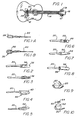
- Figures IA and IB illustrate two conventional bridge peg end treatments for the strings 20.
- Figure lA shows an end 26 which has been looped and twisted back upon itself to form a conventional loop-end. The loop-end 26 is fitted over a bridge peg in the bridge 24 or in a tailpiece to secure a string 20 (not shown).
- Figure IB illustrates a conventional ball-end 28 for a string 20, wherein a ball 30 is securely held within a looped and twisted end of the string 20.
- the ball end is engaged with a notched recess on the bridge 24, or coacts with bridge pegs 22, to lock the strings 20 to the bridge 24 of the guitar.
- a string of the invention may be secured at the "bridge end" using either of these conventional techniques, or any other suitable method.
- a steel tube 32 is fitted over the tuning post end of the string 20.
- the tube 32 is the crimped, as indicated at 34, to the string 20 to become securely interlocked therewith.
- a simple hand held crimping tool (not shown) may be used to enable the tube 32 to be crimped by a musician, or by a salesperson at a retail string sales outlet, so that the string 20 may be tailored to suit a particular instrument in the field. Excess string length may then be removed, after the tube 32 has been crimped onto the string at the desired location.
- a swageable steel tube 36 is fitted over the tuning post end of a string 20.
- the tube 36 is then multiply swaged as shown to become securely interlocked to the string end.
- the tube 36 in Figure 3 may be swaged, using a portable swaging tool, by a musician or retail sales person in the field.
- the tuning post end 42 of a string 20 is formed into a strengthened pin by being folded back sharply and then spiral twisted tightly about itself to yield a tuning post pin with a desired stiffness.
- a tube 48 is secured to the tuning post end of the string 20 by an electric spot weld, as at 50.
- a tube 56 is secured to the tuning post end of a string 20 by a suitable cement such as a cured cyanoacrylate, or a suitable polymerizable epoxy resin compound, as indicated at 58.
- a suitable cement such as a cured cyanoacrylate, or a suitable polymerizable epoxy resin compound, as indicated at 58.
- Figure 9 shows one conventional method used to secure a string to a tuning post 60, wherein, a conventional string is bent sharply on both sides of the tuning post 60 to prevent it from slipping.
- Figure 10 illustrates the installation and operation of the stiffened end of a string 20 of the present invention relative to a tuning post 60.
- a string 20, having its outer tuning post end portion 62 stiffened by, for example, a steel tube, may easily be installed upon a tuning post 60 by inserting the stiffened portion 62 through the hole of the tuning post 60 and bending the string 20 back sharply at an inside end of the stiffened portion 62.
- the stiffened portion 62 prevents the string 20 from slipping out of the tuning post 60.
- the tube or stiffened portion is desirably no longer than the diameter of the tuning post 60, so that there are no protrusions sticking out from the tuning post 60.
- the stiffness of the pin portion 62 is sufficient to prevent the string 20 from slipping relative to the post 60 and, due to the stiffness of the pin portion 62, the string 20 is secured to the post 60 by tension developed in the direction of the bridge 24, indicated in the Figure by an arrow 64.
- the free end of the string 20 is desirably cut flush to the outer end of the stiffened portion 62 so that the musician does not have to deal with the loose end after installation of the string in an instrument.
- the stiffened portion 62 cannot pull out of the tuning post hole.
- the knob (not shown) of a tuning mechanism 18 that operates the tuning post 60 can rapidly and easily be turned to wind the string 20 tightly about its tuning post 60.
Abstract
A string 20 for a musical instrument is formed, at its end for attachmentto a tuning peg, to provide a pin portion 32 that is stiffened to resist bending. Desirably the pin portion 32 is formed to have a slightly larger diameter than the remainder of the string 20, is adapted to be received freely and snugly in a transverse hole in the tuning peg and has a length substantially no greaterthan the length of the hole in the tuning peg.
Description
- This invention relates to strings for musical instruments.
- The musical field is one which has been the focus of much attention, with professional musicians and amateurs at home expressing a great deal of interest in every aspect of music and in the equipment used to perform music. This has been true both with respect to those who are active in performing music for a living and those who merely enjoy playing musical instruments as a hobby.
- Whether one considers the professional musician or the amateur, most of these people have one thing in common: they wish to deal with their musical instruments as efficiently as possible, creating the best tones, sounds and overall impressions with the greatest ease of playing, and to handle the adjustments and maintenance of the instrument with the least amount of difficulty. During the last two decades, the proliferation of interest in stringed musical instruments has intensified, particularly with respect to the guitar, banjo, mandolin and similar stringed instruments.
- Although many levels of instruments exist to provide musicians with all qualities of sound and tonal variations, there still remains one cumbersome and time-consuming process which is common to all types and grades of these instruments: changing strings. In the past, strings for musical instruments have been supplied to musicians in long, virtually unmeasured lengths. Traditionally, strings are tied onto one end of an instrument, e.g. the bridge or tailpiece, thereby providing a fixed end of the string, and are then pulled towards the tuning end of the instrument, called the "peghead". At that end, the string is twisted several times around a cylindrical "tuning peg" or "tuning post" and then the loose end threaded through a transverse hole defined radially through the tuning post. In most cases, the string has to be double threaded through the hole to prevent its smooth, silky surface from slipping loose from the post in a snake-like way and thus de-tuning the instrument at an undesirable time. Excess string then has to be removed, by breaking or cutting, so that the excess length does not pose a hazard to the musician's hands or eyes, etc.
- In developments to the traditional arrangement it has been proposed for the fixed end of the string to be twisted into a loop or provided with a machine turning (called a "bαlI-end"), both of which provided a more simplified and efficient attachment mechanism. Heretofore, very little further development has occurred concerning attachment of the fixed end of the string to the bridge or tailpiece. Loops or ball ends are still used with very satisfactory results, and they do not seem likely to require changes since they serve their purpose well and securely.
- At the other end of the string, where it must be tailored somewhat to facilitate attachment to the tuning post (and therefore must be bent, threaded and cut to length) the art has developed rather unsatisfactory. Thus, the smooth surface, for example of a hand-affixed steel string, often slips around the post, or becomes so securely tied that it is most difficult to change, and often causes skin punctures during the replacement operation.
- To the extent that the problem has been addressed at all, the industry has devised apparatuses for storing coiled amounts of string and unwinding them as one desires to install a string and attach it to the tuning post. Similarly, other attachment techniques have been used, such as providing both ends of a musical instrument string with a conventional loop or ball-end. While the attachment may thereby be rendered somewhat easier or more convenient, the ball-end or loop-end interferes with the free turning and smooth operation of the tuning post.
- One prior approach is set forth in US-A- 1,363,902, which describes a pin with a tapered shank 3 and a double flanged head 5-6. The pin 3 is adapted to become lockingly engaged in a bore 2 through a tuning key I. The drawbacks of this approach are numerous. Firstly, the fact that the pin 3 is tapered means that the pin may become stuck in the bore 2 of the tuning peg necessarily hampering easy removal and replacement of the string. Secondly, the pin 3 is mounted substantially at right angles to the string, and is large and bulky, with flanges, etc. Thus the string will not easily fit through and can not easily be threaded through any string holes in the bridge, tailpiece or elsewhere, as is commonly required in modern stringed instruments. Thirdly, the pin does not seat fully within the bore through the tuning peg but protrudes radially outwardly therefrom. Such protrusion leads to the likelihood that any coils of the string wrapped about the peg and the protruding pin would slip off during play, thereby changing diameter and thus de-tuning the instrument.
- A hitherto unsolved need has arisen for a simple and practical means to prevent the string from slipping relative to the tuning post while at the same time enabling a musician to change strings rapidly and reliably, without the usual drawbacks associated with threading the string through the tuning post and then having it slip as tension is initially applied thereto.
- This need is particularly acute for the performing professional musician who breaks a string during performance. With conventional methods and strings, removal of the broken string and its replacement requires several minutes during which the performance may be interrupted.
- A general object of the present invention is to provide a string for a musical instrument which overcomes the aforementioned difficulties of the prior art.
- According to one aspect of the invention, there is provided a string for a musical instrument, which string has a bridge peg attachment end and a tuning peg attachment end, characterised in that the tuning post attachment end is formed to provide a pin portion that is stiffened to resist bending.
- In a further aspect, the invention provides a string for a musical instrument, which string has a bridge peg attachment end and a tuning peg attachment end, characterised in that said tuning peg attachment end includes an integrally formed pin portion thereat which is slightly larger in diametral cross-section than said string, which is longitudinally strengthened to resist bending, is adapted to be received freely and snugly in a transverse hole in a tuning peg, and which has a length substantially no greater than the diametral distance of said transverse hole, thereby facilitating securing of said string to said peg without relative slippage therebetween.
- In one embodiment of this invention, the string is passed inside a steel tube and secured by a substantial crimp or swage which pinches the string inside the tube and prevents its release.
- Various other embodiments are also disclosed as part of the invention. The stiffening means can be achieved in the form of a part molded directly onto the string end portion, or by sharply folding back the end portion to double the thickness thereof followed by a tubular coating with a hardenable molding compound.
- It is therefore a feature of one embodiment of this invention that a steel tube is crimped, swaged, glued or otherwise non-removably attached to the end of a musical string to prevent its slippage from the hole of the tuning post.
- It is also a feature of an embodiment of this invention that each of the strings may be cut to a predetermined length so that a musician does not have to remove any excess length when fitting the string.
- It is additionally a feature of an embodiment of this invention that the stiffened end portion of the string has a diameter which is slightly less than the diameter of the hole through standard tuning posts, so that the end portion passes freely but snugly therethrough.
- It is still another feature of the present invention that the stiffened end portion of the string has a sufficiently small overall diameter as to pass through the tailpiece or bridge attachment members without obstruction or interference.
- It is a further feature of this invention that a musical string's snake-like sinuous character may be inhibited at the tuning post end by enlargement and stiffening thereat.
- In order that the invention may be more readily understood, and so that further features thereof may be appreciated, embodiments of the invention will now be described, by way of example, with reference to the accompanying drawings, in which:
- FIGURE I is a top plan somewhat diagrammatic view of a stringed musical instrument;
- FIGURE I A is a detail view of the conventional loop-end of a string suitable for attachment to the bridge of the musical instrument of Figure I;
- FIGURE IB is a detail view of the conventional ball-end of a string suitable for attachment to the bridge of the musical instrument of Figure I;
- FIGURE 2 is a detail view of a tuning post end portion of a string fitted with a tube in accordance with one embodiment of the present invention;
- FIGURE 3 is a detail view of a second embodiment of the present invention;
- FIGURE 4 is a detail view of a third embodiment of the present invention;
- FIGURE 5 is a detail view of a fourth embodiment of the present invention;
- FIGURE 6 is a detail view of a fifth embodiment of the present invention;
- FIGURE 7 is a detail view of a sixth embodiment of the present invention;
- FIGURE 8 is a detail view of a seventh embodiment of the present invention;
- FIGURE 9 illustrates a prior art method for double wrapping the string onto the tuning post in order to lock it in place; and
- FIGURE 10 illustrates use of the present invention to secure the string to the tuning post.
- Figure I illustrates the major components of a typical stringed guitar 10. The guitar 10 includes an enlarged
hollow body 12, aneck 14 secured to and extending from thebody 12 and terminating in apeghead 16.Tuning mechanisms 18 are mounted to thepeghead 16 and provide for attachment ofstrings 20 to thepeghead 16. Typically, guitars include either six or twelvestrings 20, and there are as manyseparate tuning mechanisms 18 as there are strings. Thestrings 20 are attached at their other ends to theguitar body 12, typically bybridge pegs 22 secured to a bridge 24. - Figures IA and IB illustrate two conventional bridge peg end treatments for the
strings 20. Figure lA shows anend 26 which has been looped and twisted back upon itself to form a conventional loop-end. The loop-end 26 is fitted over a bridge peg in the bridge 24 or in a tailpiece to secure a string 20 (not shown). Figure IB illustrates a conventional ball-end 28 for astring 20, wherein aball 30 is securely held within a looped and twisted end of thestring 20. To secure astring 20 to the bridge 24, the ball end is engaged with a notched recess on the bridge 24, or coacts withbridge pegs 22, to lock thestrings 20 to the bridge 24 of the guitar. In use, a string of the invention may be secured at the "bridge end" using either of these conventional techniques, or any other suitable method. - A number of embodiments of the present invention are illustrated in Figures 2 to 8. In all of these embodiments the
string 20 is provided with a strengthened and slightly enlarged tip portion at the tuning post end thereof. - In the embodiment of Figure 2, a
steel tube 32 is fitted over the tuning post end of thestring 20. Thetube 32 is the crimped, as indicated at 34, to thestring 20 to become securely interlocked therewith. A simple hand held crimping tool (not shown) may be used to enable thetube 32 to be crimped by a musician, or by a salesperson at a retail string sales outlet, so that thestring 20 may be tailored to suit a particular instrument in the field. Excess string length may then be removed, after thetube 32 has been crimped onto the string at the desired location. - In the embodiment of Figure 3, a swageable steel tube 36 is fitted over the tuning post end of a
string 20. The tube 36 is then multiply swaged as shown to become securely interlocked to the string end. As with thetube 32 shown in Figure 2, the tube 36 in Figure 3 may be swaged, using a portable swaging tool, by a musician or retail sales person in the field. - In the embodiment of Figure 4, the tuning
post end 38 of astring 20 is folded back, as illustrated in broken lines in the drawing. Apin 40 is then formed by a suitable molding compound which is molded around the doubled-back portion 38 of the string and then cured to hardness. - In the embodiment of Figure 5, the tuning post end 42 of a
string 20 is formed into a strengthened pin by being folded back sharply and then spiral twisted tightly about itself to yield a tuning post pin with a desired stiffness. - In the embodiment of Figure 6, a
tube 48 is secured to the tuning post end of thestring 20 by an electric spot weld, as at 50. - In the embodiment of Figure 7, a
tube 52 is secured to the tuning post end of astring 20 by any suitable attachment means. Thetube 52 has a tapered or` bullet shapedouter end 54 to facilitate insertion into the tuning post. - In the embodiment of Figure 8, a
tube 56 is secured to the tuning post end of astring 20 by a suitable cement such as a cured cyanoacrylate, or a suitable polymerizable epoxy resin compound, as indicated at 58. - Figure 9 shows one conventional method used to secure a string to a
tuning post 60, wherein, a conventional string is bent sharply on both sides of the tuningpost 60 to prevent it from slipping. In distinction, Figure 10 illustrates the installation and operation of the stiffened end of astring 20 of the present invention relative to atuning post 60. Astring 20, having its outer tuning postend portion 62 stiffened by, for example, a steel tube, may easily be installed upon a tuningpost 60 by inserting the stiffenedportion 62 through the hole of the tuningpost 60 and bending thestring 20 back sharply at an inside end of the stiffenedportion 62. The stiffenedportion 62 prevents thestring 20 from slipping out of the tuningpost 60. The tube or stiffened portion is desirably no longer than the diameter of the tuningpost 60, so that there are no protrusions sticking out from the tuningpost 60. The stiffness of thepin portion 62 is sufficient to prevent thestring 20 from slipping relative to thepost 60 and, due to the stiffness of thepin portion 62, thestring 20 is secured to thepost 60 by tension developed in the direction of the bridge 24, indicated in the Figure by anarrow 64. - It will be appreciated that the free end of the
string 20 is desirably cut flush to the outer end of the stiffenedportion 62 so that the musician does not have to deal with the loose end after installation of the string in an instrument. - Since the angle of tension force applied to the string is opposite to the axis of the tuning post's hole, the stiffened
portion 62 cannot pull out of the tuning post hole. Thus, by maintaining a slight tension on thestring 20 during installation, the knob (not shown) of atuning mechanism 18 that operates the tuningpost 60 can rapidly and easily be turned to wind thestring 20 tightly about its tuningpost 60. - When a string is to be removed, simple turning of the knob of the tuning mechanism in an unwinding direction, to "loosen" the tuning post removes tension and unravels the string. By pulling the unravelled string in the same direction as the axis of the hole in the tuning post the string and its stiffened end portion may easily be removed without need to unkink the extra bends required to be placed in the string by the conventional prior art method.
- The features disclosed in the foregoing description, in the following claims and/or in the accompanying drawings may, both separately and in any combination thereof, be material for realising the invention in diverse forms thereof.
Claims (9)
- I. A string for a musical instrument, which string has a bridge peg attachment end and a tuning peg attachment end, characterised in that the tuning post attachment end is formed to provide a pin portion that is stiffened to resist bending.
- 2. A string for a musical instrument, which string has a bridge peg attachment end and a tuning peg attachment end, characterised in that said tuning peg attachment end includes an integrally formed pin portion thereat which is slightly larger in diametral cross-section than said string, which is longitudinally strengthened to resist bending, is adapted to be received freely and snugly in a transverse hole in a tuning peg, and which has a length substantially no greater than the diametral distance of said transverse hole, thereby facilitating securing of said string to said peg without relative slippage therebetween.
- 3. A string according to claim I or claim 2, wherein said pin portion comprises a hollow cylindrical tube secured to said string.
- 4. A string according to claim 3, wherein said tube is secured to said string end portion by interference fit established by crimp deformation of said tube.
- 5. A string according to claim 3, wherein said tube is secured to said string end portion by interference fit established by swaging said tube to engage said string.
- 6. A string according to claim 3, wherein said tube is secured to said string end portion by an electric spot weld.
- 7. A string according to claim 3, wherein said tube is secured to said string by cement means for bonding said string to said tube.
- 8. A string according to claim I or claim 2, wherein said pin portion is integrally formed by sharply folding said string back to double its thickness and then by forming said pin with molding compound means surrounding said double thickness portion.
- 9. A string according to claim I or claim 2, wherein said pin portion is integrally formed by sharply folding said string back to double its thickness and then by spiral wrapping said folded back portion tightly about said string adjacent said fold for a sufficient distance to form said pin.
Applications Claiming Priority (2)
| Application Number | Priority Date | Filing Date | Title |
|---|---|---|---|
| US47913083A | 1983-03-28 | 1983-03-28 | |
| US479130 | 1983-03-28 |
Publications (2)
| Publication Number | Publication Date |
|---|---|
| EP0120363A2 true EP0120363A2 (en) | 1984-10-03 |
| EP0120363A3 EP0120363A3 (en) | 1985-05-15 |
Family
ID=23902775
Family Applications (1)
| Application Number | Title | Priority Date | Filing Date |
|---|---|---|---|
| EP84102474A Withdrawn EP0120363A3 (en) | 1983-03-28 | 1984-03-08 | A string for a musical instrument |
Country Status (2)
| Country | Link |
|---|---|
| EP (1) | EP0120363A3 (en) |
| JP (1) | JPS59180589A (en) |
Cited By (7)
| Publication number | Priority date | Publication date | Assignee | Title |
|---|---|---|---|---|
| GB2226910A (en) * | 1988-11-26 | 1990-07-11 | Hugh Manson | Termination of metallic wire musical instrument strings |
| DE4432107A1 (en) * | 1994-09-09 | 1995-04-13 | Gisbert Paech | Bell harp |
| EP0806757A2 (en) * | 1996-05-06 | 1997-11-12 | Fender Musical Instruments Corporation | Manufacturing guitar strings |
| US6677511B2 (en) | 2000-05-15 | 2004-01-13 | Velvet Strings Sa | String for musical instrument |
| WO2009075644A1 (en) * | 2007-12-13 | 2009-06-18 | Sandvik Intellectual Property Ab | Music string |
| GB2504514A (en) * | 2012-07-28 | 2014-02-05 | Andrew John Mccann | A string locking device used when restringing a musical instrument |
| DE102022108527A1 (en) | 2022-04-08 | 2023-10-12 | Hüter der Klänge GmbH | String for a musical instrument |
Families Citing this family (1)
| Publication number | Priority date | Publication date | Assignee | Title |
|---|---|---|---|---|
| JPH0741035Y2 (en) * | 1988-09-01 | 1995-09-20 | カシオ計算機株式会社 | String fixing mechanism |
Citations (4)
| Publication number | Priority date | Publication date | Assignee | Title |
|---|---|---|---|---|
| GB237342A (en) * | 1924-04-23 | 1925-07-23 | William Robert Mcclelland | Improvements in or relating to strings for musical instruments |
| DE512676C (en) * | 1927-11-05 | 1930-11-15 | Max Selbach | String for musical instruments |
| US1987069A (en) * | 1933-09-25 | 1935-01-08 | Herman H Kroeplin | Means for preventing slipping of violin strings in tuning |
| US3881236A (en) * | 1972-07-24 | 1975-05-06 | Columbia Broadcasting Syst Inc | Method of providing ball ends on guitar strings |
-
1984
- 1984-03-08 EP EP84102474A patent/EP0120363A3/en not_active Withdrawn
- 1984-03-16 JP JP59052073A patent/JPS59180589A/en active Pending
Patent Citations (4)
| Publication number | Priority date | Publication date | Assignee | Title |
|---|---|---|---|---|
| GB237342A (en) * | 1924-04-23 | 1925-07-23 | William Robert Mcclelland | Improvements in or relating to strings for musical instruments |
| DE512676C (en) * | 1927-11-05 | 1930-11-15 | Max Selbach | String for musical instruments |
| US1987069A (en) * | 1933-09-25 | 1935-01-08 | Herman H Kroeplin | Means for preventing slipping of violin strings in tuning |
| US3881236A (en) * | 1972-07-24 | 1975-05-06 | Columbia Broadcasting Syst Inc | Method of providing ball ends on guitar strings |
Cited By (9)
| Publication number | Priority date | Publication date | Assignee | Title |
|---|---|---|---|---|
| GB2226910A (en) * | 1988-11-26 | 1990-07-11 | Hugh Manson | Termination of metallic wire musical instrument strings |
| DE4432107A1 (en) * | 1994-09-09 | 1995-04-13 | Gisbert Paech | Bell harp |
| EP0806757A2 (en) * | 1996-05-06 | 1997-11-12 | Fender Musical Instruments Corporation | Manufacturing guitar strings |
| EP0806757A3 (en) * | 1996-05-06 | 1998-07-08 | Fender Musical Instruments Corporation | Manufacturing guitar strings |
| US5913257A (en) * | 1996-05-06 | 1999-06-15 | Fender Musical Instruments Corp. | Method of manufacturing guitar strings, and guitar strings resulting from such method |
| US6677511B2 (en) | 2000-05-15 | 2004-01-13 | Velvet Strings Sa | String for musical instrument |
| WO2009075644A1 (en) * | 2007-12-13 | 2009-06-18 | Sandvik Intellectual Property Ab | Music string |
| GB2504514A (en) * | 2012-07-28 | 2014-02-05 | Andrew John Mccann | A string locking device used when restringing a musical instrument |
| DE102022108527A1 (en) | 2022-04-08 | 2023-10-12 | Hüter der Klänge GmbH | String for a musical instrument |
Also Published As
| Publication number | Publication date |
|---|---|
| JPS59180589A (en) | 1984-10-13 |
| EP0120363A3 (en) | 1985-05-15 |
Similar Documents
| Publication | Publication Date | Title |
|---|---|---|
| EP0120363A2 (en) | A string for a musical instrument | |
| US20100071529A1 (en) | Musical string | |
| JP2007513359A (en) | Accessories or operation parts for musical instruments or components of musical instruments | |
| US4141271A (en) | Method and apparatus for preventing improper string return | |
| US6982372B2 (en) | Acoustic musical instrument and method | |
| US20190371283A1 (en) | Methods and articles for facilitating stringing of a stringed instrument having mechanical vibrato unit | |
| US4326444A (en) | Musical instrument string | |
| US5693899A (en) | Fully wrapped core wire musical instrument string | |
| US7947885B2 (en) | Music string | |
| US6060654A (en) | Acoustical apparatus sound system | |
| US20060016317A1 (en) | String tuning device | |
| US6563037B2 (en) | Guitar string attachment device | |
| US4581976A (en) | Reinforced musical instrument string | |
| US6891095B2 (en) | Multi-pick apparatus for a stringed instrument | |
| US4197780A (en) | Method and apparatus for stabilizing the tension of musical instrument strings | |
| US7932453B2 (en) | Tool for setting an instrument sound post | |
| US3757027A (en) | Snare drum and improved snare wire therefor | |
| US7098391B2 (en) | Protective sleeve for an instrument string and its method of application to an instrument | |
| US4852447A (en) | String arrangement for a musical instrument | |
| US5753837A (en) | Adjustable reinforced neck assembly for stringed musical instrument | |
| US20240054977A1 (en) | Tuning pin tool | |
| US10522118B1 (en) | Instrument string length measurement and marking apparatus and method of using same | |
| JP6569104B2 (en) | Bridge pin puller | |
| US10818275B2 (en) | System for preparing musical instrument strings | |
| JPS584134Y2 (en) | String instruments such as guitars |
Legal Events
| Date | Code | Title | Description |
|---|---|---|---|
| PUAI | Public reference made under article 153(3) epc to a published international application that has entered the european phase |
Free format text: ORIGINAL CODE: 0009012 |
|
| AK | Designated contracting states |
Designated state(s): DE GB |
|
| PUAL | Search report despatched |
Free format text: ORIGINAL CODE: 0009013 |
|
| AK | Designated contracting states |
Designated state(s): DE GB |
|
| 17P | Request for examination filed |
Effective date: 19851017 |
|
| STAA | Information on the status of an ep patent application or granted ep patent |
Free format text: STATUS: THE APPLICATION IS DEEMED TO BE WITHDRAWN |
|
| 18D | Application deemed to be withdrawn |
Effective date: 19861001 |