EP0119902B1 - Mikrowellenhohlraumresonator, besonders für Erzeuger elektromagnetischer Energie - Google Patents
Mikrowellenhohlraumresonator, besonders für Erzeuger elektromagnetischer Energie Download PDFInfo
- Publication number
- EP0119902B1 EP0119902B1 EP84400425A EP84400425A EP0119902B1 EP 0119902 B1 EP0119902 B1 EP 0119902B1 EP 84400425 A EP84400425 A EP 84400425A EP 84400425 A EP84400425 A EP 84400425A EP 0119902 B1 EP0119902 B1 EP 0119902B1
- Authority
- EP
- European Patent Office
- Prior art keywords
- axis
- cavity
- mirror
- generator according
- mirrors
- Prior art date
- Legal status (The legal status is an assumption and is not a legal conclusion. Google has not performed a legal analysis and makes no representation as to the accuracy of the status listed.)
- Expired
Links
- 230000003993 interaction Effects 0.000 claims description 11
- 238000010894 electron beam technology Methods 0.000 claims description 8
- 230000005672 electromagnetic field Effects 0.000 claims description 2
- 238000000926 separation method Methods 0.000 description 3
- 230000005670 electromagnetic radiation Effects 0.000 description 2
- 230000001902 propagating effect Effects 0.000 description 2
- 230000002745 absorbent Effects 0.000 description 1
- 239000002250 absorbent Substances 0.000 description 1
- 239000012141 concentrate Substances 0.000 description 1
- 230000000694 effects Effects 0.000 description 1
- 230000005684 electric field Effects 0.000 description 1
- 230000005284 excitation Effects 0.000 description 1
- 230000012447 hatching Effects 0.000 description 1
- 238000000034 method Methods 0.000 description 1
- 230000010355 oscillation Effects 0.000 description 1
- 230000003071 parasitic effect Effects 0.000 description 1
Images
Classifications
-
- H—ELECTRICITY
- H01—ELECTRIC ELEMENTS
- H01J—ELECTRIC DISCHARGE TUBES OR DISCHARGE LAMPS
- H01J23/00—Details of transit-time tubes of the types covered by group H01J25/00
- H01J23/16—Circuit elements, having distributed capacitance and inductance, structurally associated with the tube and interacting with the discharge
- H01J23/18—Resonators
- H01J23/20—Cavity resonators; Adjustment or tuning thereof
-
- H—ELECTRICITY
- H01—ELECTRIC ELEMENTS
- H01J—ELECTRIC DISCHARGE TUBES OR DISCHARGE LAMPS
- H01J25/00—Transit-time tubes, e.g. klystrons, travelling-wave tubes, magnetrons
- H01J25/02—Tubes with electron stream modulated in velocity or density in a modulator zone and thereafter giving up energy in an inducing zone, the zones being associated with one or more resonators
Definitions
- the present invention relates to a resonant cavity for microwaves, more particularly a resonant cavity used in a generator operating at several tens of gigahertz, that is to say, in millimeter and submillimeter waves.
- generators of this type there are in particular generators in which an electron beam propagates along helical paths while being guided by a uniform magnetic field along the axis of the propeller.
- the beam passes through a resonant cavity in which the transverse velocity components of the electrons interact with a transverse electric field component of the wave so as to amplify it.
- the cavities usually used in this type of generator are constituted by cylindrical cavities or with two spherical mirrors whose dimensions are calculated to operate in TE on mode.
- the aim of the present invention is to provide a resonant cavity making it possible to increase the frequency separation of the electromagnetic modes, namely to eliminate a certain number of parasitic modes.
- the subject of the present invention is a generator of millimeter and submillimeter waves of the gyrotron type comprising an electron gun emitting an electron beam along an axis and a resonant cavity positioned along said axis in which the beam d electrons interacts with an electromagnetic field, characterized in that the resonant cavity formed by a surface of revolution comprises reflective surfaces which form in each meridian plane passing through the beam axis at least four curved mirror zones positioned so that the centers of the mirror zones define the vertices of a polygon and each perpendicular to a mirror zone at its center corresponds to the bisector of the angle at the top of the polygon, the mirror zones being dimensioned so as to obtain at least one region interaction of limited length.
- the modes propagating in a resonant cavity can be analyzed as plane waves which are reflected a number of times on the walls of the cavity.
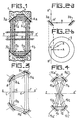
- the resonant cavity 1 consists mainly of two curved annular mirrors 3-4 of the same axis ZZ ', more particularly in the form of a spherical zone.
- the two mirrors 3,4 which face each other are positioned so that, in a meridian plane, they delimit four mirror zones 3a, 3b, 4a, 4b facing each other, the respective centers 3'a, 3'b , 4'a, 4'b form the vertices of a polygon, namely the four vertices of a rectangle in the embodiment shown.
- the four zones are inclined in the meridian plane so that the normal 5a, 5b, 6a, 6b to the said mirror zones at the level of the counters corresponds to the bisector of the angle at the corresponding vertex of the rectangle.
- the mirrors are inclined at 45 ° relative to the axis ZZ '. Therefore useful electromagnetic waves, as explained below, which are reflected successively on the different mirror zones follow the paths represented by arrows in Figure 1, the hatching representing the areas where the corresponding energy is concentrated.
- the mirror zones 3a, 3b, 4a, 4b have an appropriate curvature in the plane containing the axis whose purpose is to concentrate the energy at the level of the axis ZZ ' on two areas cd ef of length limited by a side effect due to diffraction.
- the cavity is constituted by surfaces 7 absorbing the electromagnetic radiation considered, which avoids the reflection of the diffracted rays outside the cavity.
- FIGS. 2 illustrate the reflection of two rays incident on the surface of one of the mirrors 3 or 4 constituting the cavity of FIG. 1.
- a centrifugal ray A this strikes the mirror zone 3a at A 'and is reflected vertically at A "due to the inclination of the mirror at 45 ° as shown in FIG. 2a, the ray then following the propagation path shown in FIG. 1.
- a ray B not passing through the axis and striking the mirror area also at A ', it is reflected in a direction B ".
- the cavity shown in Figure 1 it has two areas of interaction cd, ef with the electron beam. It is thus possible to carry out a premodulation of the electron beam during the first interaction, namely at the level of the cd area, most of the energy transfer from the beam to the wave occurring during the second interaction. , namely at the level of the ef zone.
- the annular mirrors may be, as shown in FIG. 3, constituted by two asymmetrical annular mirrors 8, 9 having different radii in the meridian plane.
- the polygon of the centers of the mirror zones 8a, 8b, 9a, 9b is constituted by an isosceles trapezoid.
- Figure 3 there is shown in the same manner as in Figure 1, the path of the electromagnetic propagation and the areas where the energy is concentrated.
- the path followed by the electromagnetic waves in the cavity of FIG. 3 is identical to that of FIG. 1, the only difference residing in the fact that the interaction zone cd is more important than the interaction zone ef, which causes a greater concentration of energy in the ef zone.
- the mirror zones 10, 11, 12, 13 are positioned as shown in FIG. 4.
- the mirror zones 10, 11, 12, 13 are obtained from four mirrors in a spherical or parabolic cap for example arranged around the axis ZZ 'which remains the axis of symmetry of the electron beam and the magnetic field.
- Each mirror now has its own axis 10a - 10a ', 11b - 11b', 12c - 12c ', 13d - 13d' and the polygon having the above axes for bisector is formed by two triangles opposite by the vertex.
- the successive radial modes correspond to a variation of the phase of 21t when it is counted along a complete path of the ray on itself.
- one in two radial modes corresponds to fields in phase opposition in the region of the axis.
- only one in two radial modes can interact.
- the surfaces surrounding the mirrors are formed by elements absorbing the electromagnetic radiation present or by surfaces covered with an absorbent layer produced for example in "carberlox".
- the cavities described above are used more particularly in generators of radio waves of the gyrotron type. However, it is obvious to those skilled in the art that these cavities can be used in other applications requiring mode separation.
Landscapes
- Particle Accelerators (AREA)
- Control Of Motors That Do Not Use Commutators (AREA)
- Inductance-Capacitance Distribution Constants And Capacitance-Resistance Oscillators (AREA)
- Microwave Tubes (AREA)
Claims (7)
Applications Claiming Priority (2)
| Application Number | Priority Date | Filing Date | Title |
|---|---|---|---|
| FR8304056A FR2542504B1 (fr) | 1983-03-11 | 1983-03-11 | Cavite resonnante pour hyperfrequences, en particulier pour generateurs d'energie electromagnetique |
| FR8304056 | 1983-03-11 |
Publications (2)
| Publication Number | Publication Date |
|---|---|
| EP0119902A1 EP0119902A1 (de) | 1984-09-26 |
| EP0119902B1 true EP0119902B1 (de) | 1987-10-14 |
Family
ID=9286781
Family Applications (1)
| Application Number | Title | Priority Date | Filing Date |
|---|---|---|---|
| EP84400425A Expired EP0119902B1 (de) | 1983-03-11 | 1984-03-02 | Mikrowellenhohlraumresonator, besonders für Erzeuger elektromagnetischer Energie |
Country Status (5)
| Country | Link |
|---|---|
| US (1) | US4661744A (de) |
| EP (1) | EP0119902B1 (de) |
| JP (1) | JPS59175202A (de) |
| DE (1) | DE3466830D1 (de) |
| FR (1) | FR2542504B1 (de) |
Families Citing this family (7)
| Publication number | Priority date | Publication date | Assignee | Title |
|---|---|---|---|---|
| DE3483945D1 (en) * | 1983-09-30 | 1991-02-21 | Toshiba Kawasaki Kk | Gyrotron. |
| JPS61153924A (ja) * | 1984-12-26 | 1986-07-12 | Toshiba Corp | ジヤイロトロン装置 |
| EP0281858B1 (de) * | 1987-03-03 | 1991-07-17 | Centre de Recherches en Physique des Plasmas | Hochleistungs-Gyrotron zur Erzeugung elektromagnetischer Millimeter- oder Submillimeterwellen |
| FR2625836B1 (fr) * | 1988-01-13 | 1996-01-26 | Thomson Csf | Collecteur d'electrons pour tube electronique |
| EP0393485A1 (de) * | 1989-04-19 | 1990-10-24 | Asea Brown Boveri Ag | Quasi-optisches Gyrotron |
| FR2672730B1 (fr) * | 1991-02-12 | 1993-04-23 | Thomson Tubes Electroniques | Dispositif convertisseur de modes et diviseur de puissance pour tube hyperfrequence et tube hyperfrequence comprenant un tel dispositif. |
| CN102956415B (zh) * | 2011-08-29 | 2015-11-04 | 中国科学院电子学研究所 | 一种回旋管准光输出系统的反射镜曲面的设计方法 |
Family Cites Families (15)
| Publication number | Priority date | Publication date | Assignee | Title |
|---|---|---|---|---|
| DE707253C (de) * | 1934-05-16 | 1941-06-17 | Julius Pintsch Kom Ges | Reflektoranordnung fuer drahtlose Zeichenuebertragung |
| GB576442A (en) * | 1941-01-27 | 1946-04-04 | Harry Melville Dowsett | Improvements in radiating systems of electro-magnetic waves |
| NL128040C (de) * | 1960-10-07 | |||
| US3267383A (en) * | 1963-05-27 | 1966-08-16 | Ibm | Particle accelerator utilizing coherent light |
| US3518427A (en) * | 1968-06-05 | 1970-06-30 | Atomic Energy Commission | Universal planar x-ray resonator |
| US3688218A (en) * | 1971-01-29 | 1972-08-29 | Us Army | Stimulated radiation cavity reflector |
| US3979695A (en) * | 1974-12-20 | 1976-09-07 | Honeywell Inc. | High order beam mode resonator |
| SU530606A1 (ru) * | 1975-04-04 | 1980-12-30 | Ananev Yu A | Неустойчивый резонатор оптического квантовоно генератора |
| US4179192A (en) * | 1976-06-14 | 1979-12-18 | The Perkin-Elmer Corporation | Laser fusion optical system |
| US4189660A (en) * | 1978-11-16 | 1980-02-19 | The United States Of America As Represented By The United States Department Of Energy | Electron beam collector for a microwave power tube |
| SU777763A1 (ru) * | 1978-12-26 | 1980-11-07 | Днепропетровское Отделение Института Механики Ан Украинской Сср | Открытый резонатор |
| US4287488A (en) * | 1979-11-02 | 1981-09-01 | The United States Of America As Represented By The United States Department Of Energy | Rf Feedback free electron laser |
| SU938333A1 (ru) * | 1980-10-17 | 1982-06-23 | Ордена Трудового Красного Знамени Институт Радиотехники И Электроники Ан Ссср | Генератор СВЧ-колебаний |
| GB2096392B (en) * | 1981-04-06 | 1985-04-03 | Varian Associates | Collector-output for hollow beam electron tubes |
| US4496913A (en) * | 1982-11-24 | 1985-01-29 | The United States Of America As Represented By The Secretary Of The Army | Millimeter wave power combiner using concave reflectors |
-
1983
- 1983-03-11 FR FR8304056A patent/FR2542504B1/fr not_active Expired
-
1984
- 1984-03-01 US US06/585,292 patent/US4661744A/en not_active Expired - Fee Related
- 1984-03-02 DE DE8484400425T patent/DE3466830D1/de not_active Expired
- 1984-03-02 EP EP84400425A patent/EP0119902B1/de not_active Expired
- 1984-03-12 JP JP59045758A patent/JPS59175202A/ja active Pending
Also Published As
| Publication number | Publication date |
|---|---|
| DE3466830D1 (en) | 1987-11-19 |
| EP0119902A1 (de) | 1984-09-26 |
| US4661744A (en) | 1987-04-28 |
| JPS59175202A (ja) | 1984-10-04 |
| FR2542504A1 (fr) | 1984-09-14 |
| FR2542504B1 (fr) | 1986-02-21 |
Similar Documents
| Publication | Publication Date | Title |
|---|---|---|
| EP0564359B1 (de) | Mikrowellenstrahler und Plasmareaktor unter Verwendung dieser Einrichtung | |
| EP0274074B1 (de) | Erreger für die Ausleuchtung einer Übertragungsantenne | |
| EP2130266B1 (de) | Antenne mit einem resonator mit einer filterungsbeschichtung und system mit einer solchen antenne | |
| EP0598656A1 (de) | Elementarstrahler für Gruppenantenne und solche Strahler enthaltende Baugruppe | |
| EP0407558B1 (de) | Mikrowellen-verstärker oder oszillator-anordnung | |
| EP1568104B1 (de) | Mehrfachstrahlantenne mit photonischem bandlückenmaterial | |
| EP0119902A1 (de) | Mikrowellenhohlraumresonator, besonders für Erzeuger elektromagnetischer Energie | |
| EP0296007A1 (de) | In Flüstergalerie-Modi angeregter Mikrowellenresonator | |
| EP1554777B1 (de) | Mehrfachstrahlantenne mit photonischem bandlückenmaterial | |
| JP2869861B2 (ja) | 準光学共振器を用いたミリ波サブミリ波用装置 | |
| FR2578357A1 (fr) | Gyrotron | |
| EP0131512A1 (de) | Doppelreflektorantenne mit fast ringflächiger Strahldeckung | |
| EP1444715A2 (de) | Mikrowellengenerator mit einer virtuellen kathode | |
| FR2568057A1 (fr) | Tube a hyperfrequences | |
| EP0049198A1 (de) | Elektronenbeschleuniger sowie Millimeter- und Submillimeterwellengenerator mit einem solchen Beschleuniger | |
| EP2936537B1 (de) | Mikrowellengenerator mit oszillierender virtueller kathode und offenen reflektoren | |
| US5719470A (en) | Gyrotron capable of outputting a plurality of wave beams of electromagnetic waves | |
| EP0020196A1 (de) | Scheibenförmige Mikrowellenmehrelementenantenne mit Speiseanordnung und deren Verwendung bei Radar | |
| FR2538959A1 (fr) | Lentille hyperfrequence bi-bande, son procede de fabrication et antenne radar bi-bande de poursuite | |
| WO2003065507A1 (fr) | Antenne de reception pour couverture multi-faisceaux | |
| EP0124396A1 (de) | Elektronenstrahlinjektionsgerät für einen Mikrowellengenerator | |
| BE1003551A3 (fr) | Cyclotrons focalises par secteurs. | |
| RU1836748C (ru) | Квазиоптический вибрационный гиротрон | |
| EP0109322A1 (de) | Doppelreflektorantenne für einen Nachführungsradar mit verbesserter Zielauffassung | |
| FR2526582A1 (fr) | Procede et appareil pour produire des micro-ondes |
Legal Events
| Date | Code | Title | Description |
|---|---|---|---|
| PUAI | Public reference made under article 153(3) epc to a published international application that has entered the european phase |
Free format text: ORIGINAL CODE: 0009012 |
|
| AK | Designated contracting states |
Designated state(s): CH DE GB LI |
|
| 17P | Request for examination filed |
Effective date: 19841004 |
|
| GRAA | (expected) grant |
Free format text: ORIGINAL CODE: 0009210 |
|
| AK | Designated contracting states |
Kind code of ref document: B1 Designated state(s): CH DE GB LI |
|
| REF | Corresponds to: |
Ref document number: 3466830 Country of ref document: DE Date of ref document: 19871119 |
|
| GBT | Gb: translation of ep patent filed (gb section 77(6)(a)/1977) | ||
| PLBE | No opposition filed within time limit |
Free format text: ORIGINAL CODE: 0009261 |
|
| STAA | Information on the status of an ep patent application or granted ep patent |
Free format text: STATUS: NO OPPOSITION FILED WITHIN TIME LIMIT |
|
| 26N | No opposition filed | ||
| PGFP | Annual fee paid to national office [announced via postgrant information from national office to epo] |
Ref country code: CH Payment date: 19920210 Year of fee payment: 9 |
|
| PGFP | Annual fee paid to national office [announced via postgrant information from national office to epo] |
Ref country code: GB Payment date: 19920220 Year of fee payment: 9 Ref country code: DE Payment date: 19920220 Year of fee payment: 9 |
|
| PG25 | Lapsed in a contracting state [announced via postgrant information from national office to epo] |
Ref country code: GB Effective date: 19930302 |
|
| PG25 | Lapsed in a contracting state [announced via postgrant information from national office to epo] |
Ref country code: LI Effective date: 19930331 Ref country code: CH Effective date: 19930331 |
|
| GBPC | Gb: european patent ceased through non-payment of renewal fee |
Effective date: 19930302 |
|
| REG | Reference to a national code |
Ref country code: CH Ref legal event code: PL |
|
| PG25 | Lapsed in a contracting state [announced via postgrant information from national office to epo] |
Ref country code: DE Effective date: 19931201 |