EP0119784A1 - Betätigungseinrichtung für den Regulierungsmechanismus einer Kraftfahrzeugkupplung - Google Patents
Betätigungseinrichtung für den Regulierungsmechanismus einer Kraftfahrzeugkupplung Download PDFInfo
- Publication number
- EP0119784A1 EP0119784A1 EP84301465A EP84301465A EP0119784A1 EP 0119784 A1 EP0119784 A1 EP 0119784A1 EP 84301465 A EP84301465 A EP 84301465A EP 84301465 A EP84301465 A EP 84301465A EP 0119784 A1 EP0119784 A1 EP 0119784A1
- Authority
- EP
- European Patent Office
- Prior art keywords
- actuator
- release bearing
- actuator according
- output member
- cover
- Prior art date
- Legal status (The legal status is an assumption and is not a legal conclusion. Google has not performed a legal analysis and makes no representation as to the accuracy of the status listed.)
- Withdrawn
Links
Images

Classifications
-
- F—MECHANICAL ENGINEERING; LIGHTING; HEATING; WEAPONS; BLASTING
- F16—ENGINEERING ELEMENTS AND UNITS; GENERAL MEASURES FOR PRODUCING AND MAINTAINING EFFECTIVE FUNCTIONING OF MACHINES OR INSTALLATIONS; THERMAL INSULATION IN GENERAL
- F16D—COUPLINGS FOR TRANSMITTING ROTATION; CLUTCHES; BRAKES
- F16D25/00—Fluid-actuated clutches
- F16D25/08—Fluid-actuated clutches with fluid-actuated member not rotating with a clutching member
- F16D25/082—Fluid-actuated clutches with fluid-actuated member not rotating with a clutching member the line of action of the fluid-actuated members co-inciding with the axis of rotation
- F16D25/083—Actuators therefor
-
- F—MECHANICAL ENGINEERING; LIGHTING; HEATING; WEAPONS; BLASTING
- F16—ENGINEERING ELEMENTS AND UNITS; GENERAL MEASURES FOR PRODUCING AND MAINTAINING EFFECTIVE FUNCTIONING OF MACHINES OR INSTALLATIONS; THERMAL INSULATION IN GENERAL
- F16D—COUPLINGS FOR TRANSMITTING ROTATION; CLUTCHES; BRAKES
- F16D25/00—Fluid-actuated clutches
- F16D25/08—Fluid-actuated clutches with fluid-actuated member not rotating with a clutching member
- F16D25/082—Fluid-actuated clutches with fluid-actuated member not rotating with a clutching member the line of action of the fluid-actuated members co-inciding with the axis of rotation
- F16D25/087—Fluid-actuated clutches with fluid-actuated member not rotating with a clutching member the line of action of the fluid-actuated members co-inciding with the axis of rotation the clutch being actuated by the fluid-actuated member via a diaphragm spring or an equivalent array of levers
Definitions
- the present invention relates to an actuator for a motor vehicle clutch and is particularly but not exclusively concerned with improvements in slave cylinders for actuating vehicle clutches.
- actuators include actuating means, e.g. a piston, for transmitting movement through an output member to a release bearing for the clutch. It is most important to keep working parts of actuators as clean as possible during use and an object of one aspect of the present invention is to improve sealing of such actuators against ingreaseof foreign matter.
- an actuator including actuating means for transmitting movement through an output member to a release bearing for the clutch, characterised in that said output member includes a resilient lip which slidably engages an adjacent portion of the actuator to form a seal.
- the output member comprises a sleeve which may converge towards the axis of the sleeve. Sealing may be enhanced by forming the lip so that it terminates at;a sharp tip.
- the actuating means is a piston slidable in a chamber, the chamber being defined between first and second members and said lip engaging said first member.
- the first and second members may be tubular with the first tubular member disposed coaxially within the second tubular member.
- sealing lip provides an effective and convenient seal against ingrease of unwanted matter into the working parts of the actuator.
- An object of another aspect of the invention is to provide a convenient means of limiting displacement of the clutch release bearing where biasing means is provided for constantly urging the release bearing in a given direction.
- an actuator for a motor vehicle clutch including actuating means for transmitting movement to a release bearing for the clutch, characterised in that there is provided biasing means for constantly urging the release bearing in a given direction and a protective cover fast, in use, with said release bearing, said cover being co-operable with stop means to limit displacement of said release bearing by said biasing means.
- a protective cover may also be used in actuators of the kind referred to in the four immediately preceding paragraphs.
- the cover is tubular and surrounds a tubular member housing said actuating means, said cover including an inwardly directed flange which slidably engages said tubular member.
- the cover may include an inward projection extending longitudinally thereof to restrict rotational novement of the cover.
- the cover may be formed integrally with the output member.
- An object of a further aspect of the invention is to provide an actuator having an improved shipping and installation device e.g. a strap, to inhibit unwanted movement of a working part of the actuator during shipping and installation. Therefore according to a further aspect of the invention there is provided an actuator including acutating means for transmitting movement through an output member to a release bearing for the clutch, characterised in that there is provided a shipping and installation device comprising elongate connector means fast at one end to a casing of the actuator and fast at the end to a holding portion so as to inhibit unwanted movement of said output member during shipping, said connector means having a portion of reduced strength such that first actuation of said actuator causes said connector means to break at said portion of reduced strength whereby said actuator is thereafter free to operate normally.
- a shipping and installation device may also be used with an actuator of the kind set out in any of the eight immediately preceding paragraphs where the actuating means transmits movement through an output member.
- the holding portion of the shipping and installation device may be annular.
- the holding portion may be attached to or integral with the said output member.
- the shipping and installation device may be attached to or integral with said cover.
- An object of yet another aspect of the invention is to provide an actuator having a simplified construction for defining a chamber which houses a piston. Therefore according to this aspect of the invention there is provided an actuator for a motor vehicle clutch including a piston slidable within a chamber for transmitting movement to a release bearing for the clutch, characterised in that said chamber is defined by first and second members made integrally in one piece. Such an arrangement may be used in an actuator according to any of the twelve immedaitely preceding paragraphs where the actuating means is a piston.
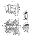
- a motor vehicle transmission comprises a friction clutch assembly 11 and a gearbox or transmission 12 enclosed in a casing 15.
- a driveshaft 13 drives the gearbox 12 from the clutch assembly 11.
- a bell housing 514, surrounding the clutch assembly 11, is bolted on the rear face of the motor vehicle engine, not shown.
- the rear face 21 of the bell housing 14 is bolted to the face 22 of the gearbox casing 15.
- An annular hydraulic slave cylinder 16 is disposed around the driveshaft 13 within the bell housing 14.
- the slave cylinder 16 has a radially outwardly projecting portion or lug 17 which is disposed in a radial groove or channel 18 formed in the rear face 21 of the clutch bell housing 14 attached to the face 22 of the gearbox casing 15 such that the projecting portion or lug 17 is sandwiched between the face 21 of the bell housing 14 and the face 22 of the gearbox housing 15.
- a generally annular elastomeric collar 23 is placed around the projecting portion or lug 17 such as to securely hold the slave cylinder projecting portion or lug 17 in the groove or channel 18 in the bell housing face 21 and against the face 22 of the gearbox casing 15.
- a pair of fluid passageways 24 and 25 run the length of the projecting portion or lug 17 into the slave cylinder 16.
- One passageway, for example passageway 24, is provided at its open end with a bleed nipple 26, and the other passageway 25 is connected via a hydraulic fluid conduit 27 to a master cylinder 28.
- the master cylinder is provided with a built-in hydraulic fluid reservoir 29 and has an input rod 30 pivotally connected at an end to a clutch control pedal 32 installed within the driver compartment-of a motor vehicle, not shown.
- the rod 30, as is well known, is connected to a piston, not shown, disposed in the master cylinder 28 for displacing the hydraulic fluid through the line 27 to the slave cylinder 16 when the clutch pedal 32 is depressed.
- the hydraulic fluid is displaced, through the passageway 25 in the slave cylinder radially projecting portion or lug 17, into the housing 33 of the slave cylinder 16 which is provided with an annular chamber 34.
- the annular chamber 34 is formed between two concentric tubular portions 36 and 38 which are preferably cast integrally together with the projecting portion or lug'17, for example of aluminum, in a single piece.
- the portions 36, 38 could.be two separate members suitably disposed relative to each other, e.g. bolted together with sealing means for preventing leakage of hydraulic fluid to the ambient.
- An annular piston 40 constituting the aforesaid actuating means, is reciprocably and slidably disposed in the cylinder housing 33 between the two concentric tubular portions 36 and 38, the piston 40 having a relatively thin cylindrical portion slidably fitting about the periphery of the inner tubular portion 36, as shown at 42, and an integrally formed larger diameter annular head portion 44 slidably fitting between the concentric tubular portions 36 and 38.
- An elastomeric seal 46 of V-shaped section is freely disposed in the annular chamber 34 above the annular head 44 of the piston 40, so as to prevent leakage of fluid from the annular chamber 34 past the piston 40.
- a metallic sleeve or carrier 48 constituting the aforesaid output member, is slidably disposed around the periphery of the inner tubular portion 36 of the cylinder housing 33.
- the carrier 48 has a flanged end postion 50 freely engaged with the end face 52 of the cylindrical portion 42 of the piston 40, and another flange portion 54 disposed at its other end having a bent-over rim 56 fixedly supporting the outer race 58 of a ball bearing 60 forming the clutch release bearing, the bearing outer race 58 being for example press-fitted within the carrier rim 56.
- the inner race 62 of the release bearing 60 is arranged.to engage the end of the clutch release fingers 64 such that when the release bearing 60 is displaced from the position indicated in full line at Fig. 3 to the position shown in phantom line, the clutch 11, Fig. 1 is released.
- a protective dust cover 66 surrounds a portion
- the dust cover 66 is generally cylindrical in shape and is molded of plastic such as nylon. One-end of the dust cover 66 is formed with an inwardly radially projecting flange or lip 68 having an inner edge 70 in sliding engagement with the peripheral surface of the cylinder outer tubular portion 38. The other end of the dust cover 66 has an outwardly projecting flange portion 72 abutting against the flange portion 54 of the carrier 48.
- a coil spring 74 is held in compression between the flange portion 54 of the carrier 48 and an annular abutment 76 formed on a radially outwardly extending flange portion 78 of the cylinder housing 33, and thus tends to urge the flange 72 of the dust cover 66 engaged with the flange portion 54 of the carrier 48 with the result that when the release bearing 60 is reciprocated, the dust cover 66 reciprocates in unison with the release bearing, the inner edge 70 of the dust cover lip 68 remaining in engagement with the peripheral surface of the outer tubular portion 36 of the slave cylinder housing 33.
- the slave cylinder housing 33 has a pair.of diametrically arranged outwardly projecting lugs 80 disposed at the end of the outer tubular portion 38 of the slave cylinder housing 33.
- the lugs 80 are arranged within the dust cover 66 by snapping the edge lip 68 of the dust cover over the outwardly projecting lugs 80.
- Fig. 1 Preferably, and as best shown at Fig.
- the dust cover 66 is provided with a pair of diametrically disposed longitudinal projections, in the form of inwardly directed U-shaped channels or dimples 82, which limit the permissible rotation of the dust cover 66 relative to the cylinder casing 33 to a maximum of 180° as a result of lateral abutment of the U-channel or dimple side-walls with a side of the lugs 80.
- the dust cover 66 in addition to acting as a seal preventing introduction of dirt below the dust cover, acts as a retainer preventing travel of the carrier 48 and the release bearing 60 after assembly of the slave cylinder 16 beyond the limits defined by the inner face of the dust cover lip 68 engaging the lugs 80, under the urging action of the compressed coil spring 74.
- the coil spring 74 is relatively weak and operates only to urge the release bearing 60 constantly in engagement with the end of the fingers 64 of the clutch release mechanism, after installation of the slave cylinder 16 in a motor vehicle transmission.
- the inner race 62 of the release bearing 60 is free rotating.
- the structure of the slave cylinder 16 as a result of a slight modification of the carrier 48 causing the carrier and flange 54 and rim 56 to engage the inner race of a release bearing, may be adapted to reciprocate a release bearing whose outer race is free-rolling and in engagement with the end of the fingers 64 of a clutch release mechanism.
- the clutch assembly 11, Fig. 1 may be a bent finger diaphragm spring clutch, as schematically illustrated or, alternatively, it may be a flat finger diaphragm spring clutch, or a coil spring clutch.
- a restraining strap for shipping and installation designated generally at 84, is provided for retracting the release bearing 60 to the position shown in full lines in Fig. 3, after assembly of the slave cylinder 16, against the action of the compressed coil spring 74.
- the restraining strap 84 holds the release bearing 60 and hence carrier 48 in a retracted position during filling of the hydraulic system with hydraulic fluid, during shipment to a motor vehicle manufacturer and during assembly of the hydraulic clutch release system on a motor vehicle.
- Prefilling of the system may be effected by filling the reservoir 29, Fig. 2, the master cylinder 28, the line 27 and the slave cylinder 16 with hydraulic fluid at a pressure slightly over atmospheric pressure, while the bleed nipple 26 is open until all atmospheric air is evacuated from the system.
- atmospheric air may be evacuated from the whole apparatus and the apparatus subsequently filled with fluid.
- prefilling of the apparatus facilitates testing of the apparatus after assembly to check for leakage and proper operation, before shipment to a motor vehicle manufacturer.
- the restraining strap 84 is preferably molded of plastics, such as nylon, and comprises an annular collar 86 provided with a pair of substantially parallel inwardly directed end flanges 88 and 90 (Figs. 3 - 5) fitting over respectively a flange 92 formed on the end of a rim portion 56 of the carrier 48 and the end of the flange 72 of the dust cover 66 may be molded in a single piece, not shown.
- a pair of bands or strips 94 are integrally molded with and extend from the annular collar 86, the free end of each band or strip 94 terminating at an integral strut 96 disposed transversely, e.g.
- each band or strip 94 of the restraining strap 84 is provided with a weakened portion 100, which may be a portion of reduced thickness ,as will be the result of forming a V-groove, as shown, on the surface of the band or strip 94, or a portion of reduced width, or both.
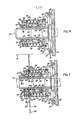
- the structure of the casing 33 of the slave cylinder 16 of Figs. 7 and 8 is identical to that of Figs. 2 - 5, i.e. the casing 33 is preferably made of a single-piece casting, with integral concentric tubular portions 36 and 38 and an integral radially projecting portion or lug 17, not shown at Figs. 7 and 8.
- movements of the annular piston d0 are transmitted to the release bearing 60 by means of a single-piece molded carrier 48 made of plastic, such as nylon for example.
- the carrier 48 has a tubular body 102, preferably provided with longitudinal grooves on a portion of its internal surface, as shown at 104, forming lubricant reservoirs and decreasing the internal surface area of the carrier tubular body 102 in sliding engagement with the peripheral surface of the cylinder inner tubular portion 36.
- the carrier tubular body 102 has, at an end, an outwardly projecting flange 106 of relatively small diameter abutting against the annular outer end face 52 of the cylindrical portion 42 of the piston 40.
- the outer race 58 of the release bearing 60 is supported from the carrier 48, at the other end of the carrier tubular body 102, by way of a radially outwardly extending integral flange 108 having a forwardly extending rim 110 in which is nested the outer race 58 of the release bearing 60.
- a plurality of ribs 112 are integrally formed in the back of the flange 108, extending generally between the flange 108 and the end flange 106 of the carrier tubular body 102 to increase the rigidity of the carrier 48.
- the restraining strap 84 and the dust cover 66 are formed integrally of a single-piece molding provided at one end with an annular rim or collar 114 having an edge lip 116 adapted to snap over a raidal annular projection 118 of the carrier flange 108.
- the band or strips 94 of the restraining strap 84 are molded radially as illustrated in dash lines, and the end of each strip or band 94 integrally connected to the annular rim or collar 114 is preferably longitudinally slit on each side, as shown at 120, such as to curve progressively, as shown at 122, when the lug 96 at the end of each strip or band 94 is passed through the T-slot 98 in the cylinder casing flange 78.
- the annular rim or collar 114 of the restraining strap 84 has an inwardly directed integral flange portion 124, disposed behind the carrier flange 108 and integrally forming the end of the dust cover 66, which is of the same shape as previously described.
- the casing lugs 80 at the end of the outer tubular portion 38 of the slave cylinder casing 33 over which is snapped the lip or flange 68 of the dust cover 66 are present in the structure of Fig. 7, but not shown.
- the present invention also contemplates forming the carrier 48 and the restraining strap 84 of a single piece plastic molding, as illustrated at Fig. 8, wherein the strips or bands 94 of the restraining strap 84 are shown molded integrally attached to the flange 108 of the carrier 48.
- the dust cover 66 is molded as a separate unit having an outwardly.
- An important feature of the carrier 48 of Figs. 7 - 8 is the provision of a resilient flexible lip 134 formed at the outer end, or front edge, of the carrier tubular body 102.
- the carrier 48 is molded with the flexible lip 134 at the front edge of the tubular body 102 inwardly directed or converging toward the centerline of the carrier tubular body 102, Fig. 9, such that when the carrier 48 is installed around the periphery of the inner tubular portion 36 of the casing 33, the lip 134 is elastically urged at its tip 136 in tight engagement with the peripheral surface of the cylinder inner tubular portion 36 such as to form a seal preventing introduction of dirt into the internal bore of the carrier.
- the sharp tip 136 at the lip 134 further acts as a convenient means for wiping dirt that may collect around the periphery of the inner tubular portion 36 during normal service of the motor vehicle on which the clutch actuating slave cylinder 16 is installed.
Applications Claiming Priority (8)
| Application Number | Priority Date | Filing Date | Title |
|---|---|---|---|
| US06/477,160 US4585107A (en) | 1983-03-21 | 1983-03-21 | Throw-out bearing carrier member for motor vehicle clutch control mechanism |
| US06/477,161 US4585108A (en) | 1983-03-21 | 1983-03-21 | Hydraulic slave cylinder for motor vehicle clutch control mechanism |
| US477160 | 1983-03-21 | ||
| US06/477,159 US4585106A (en) | 1982-05-28 | 1983-03-21 | Annular slave cylinder for motor vehicle clutch control mechanism |
| US477162 | 1983-03-21 | ||
| US06/477,162 US4585109A (en) | 1983-03-21 | 1983-03-21 | Motor vehicle clutch control mechanism |
| US477159 | 1983-03-21 | ||
| US477161 | 1983-03-21 |
Publications (1)
| Publication Number | Publication Date |
|---|---|
| EP0119784A1 true EP0119784A1 (de) | 1984-09-26 |
Family
ID=27504220
Family Applications (1)
| Application Number | Title | Priority Date | Filing Date |
|---|---|---|---|
| EP84301465A Withdrawn EP0119784A1 (de) | 1983-03-21 | 1984-03-06 | Betätigungseinrichtung für den Regulierungsmechanismus einer Kraftfahrzeugkupplung |
Country Status (1)
| Country | Link |
|---|---|
| EP (1) | EP0119784A1 (de) |
Cited By (12)
| Publication number | Priority date | Publication date | Assignee | Title |
|---|---|---|---|---|
| FR2544430A1 (fr) * | 1983-04-15 | 1984-10-19 | Skf Kugellagerfabriken Gmbh | Dispositif d'actionnement hydraulique pour embrayage, en particulier pour vehicules automobiles |
| EP0172011A1 (de) * | 1984-08-15 | 1986-02-19 | Automotive Products Public Limited Company | Elektrische Schalter in einem hydraulischen Zylinder eingebaut |
| FR2581146A1 (fr) * | 1985-04-24 | 1986-10-31 | Dana Corp | Butee d'embrayage. |
| EP0177212B1 (de) * | 1984-09-20 | 1990-01-10 | Automotive Products Public Limited Company | Betätigungsorgan für eine Motorfahrzeugkupplung |
| FR2651841A1 (fr) * | 1989-09-13 | 1991-03-15 | Automotive Prod France | Cylindre hydraulique recepteur notamment pour embrayage de vehicule automobile. |
| EP0433466A1 (de) * | 1989-07-04 | 1991-06-26 | Kabushiki Kaisha Kubota | Betätigungsvorrichtung für kraftwagenkupplung |
| FR2701076A1 (fr) * | 1993-02-03 | 1994-08-05 | Valeo | Dispositif de débrayage à actionneur hydraulique à encliqueter sur un embrayage de type tiré. |
| WO1997042426A1 (en) * | 1996-05-03 | 1997-11-13 | Automotive Products France S.A. | Hydraulic actuators |
| WO1997045652A1 (de) * | 1996-05-24 | 1997-12-04 | INA Wälzlager Schaeffler oHG | Nehmerzylinder mit einem druckstutzen, an dem ein elastisches verschlusselement befestigt ist |
| DE19724836A1 (de) * | 1997-06-12 | 1998-12-17 | Schaeffler Waelzlager Ohg | Nehmerzylinder, dessen Leitungsanschluß abgedichtet durch eine Öffnung des Kupplungsgehäuses geführt ist |
| WO1999064759A1 (en) * | 1998-06-06 | 1999-12-16 | Automotive Products Plc | Clutches |
| KR100540444B1 (ko) * | 1996-05-24 | 2006-03-16 | 루크 라멜렌 운트 쿠프룽스바우 베타일리궁스 카게 | 탄성밀봉부재를갖는압력연결관을구비하는슬레이브실린더 |
Citations (8)
| Publication number | Priority date | Publication date | Assignee | Title |
|---|---|---|---|---|
| GB599807A (en) * | 1943-12-24 | 1948-03-22 | Pesco Products Co | Improvements in or relating to arrangements for operating clutches |
| GB1550613A (en) * | 1976-06-04 | 1979-08-15 | Automotive Prodlucts Ltd | Fluid pressure servo motors |
| FR2512143A1 (fr) * | 1981-08-27 | 1983-03-04 | Skf Kugellagerfabriken Gmbh | Dispositif de debrayage hydraulique, en particulier pour des embrayages de vehicules automobiles |
| EP0074671A1 (de) * | 1981-09-15 | 1983-03-23 | LuK Lamellen und Kupplungsbau GmbH | Druckmittelbetätigte Ausrückvorrichtung für Kupplungen, insbesondere für Kraftfahrzeugkupplungen |
| GB2109504A (en) * | 1981-11-12 | 1983-06-02 | Skf Kugellagerfabriken Gmbh | Removing oil and dust from piston cylinder assembly |
| GB2112490A (en) * | 1981-12-15 | 1983-07-20 | Automotive Products Plc | Hydraulic slave cylinder for a clutch release bearing |
| GB2116282A (en) * | 1982-02-26 | 1983-09-21 | Fichtel & Sachs Ag | Hydraulically actuatable rolling bearing friction clutch release device |
| GB2121504A (en) * | 1982-05-28 | 1983-12-21 | Automotive Products Plc | Hydraulic slave cylinder for clutch release |
-
1984
- 1984-03-06 EP EP84301465A patent/EP0119784A1/de not_active Withdrawn
Patent Citations (8)
| Publication number | Priority date | Publication date | Assignee | Title |
|---|---|---|---|---|
| GB599807A (en) * | 1943-12-24 | 1948-03-22 | Pesco Products Co | Improvements in or relating to arrangements for operating clutches |
| GB1550613A (en) * | 1976-06-04 | 1979-08-15 | Automotive Prodlucts Ltd | Fluid pressure servo motors |
| FR2512143A1 (fr) * | 1981-08-27 | 1983-03-04 | Skf Kugellagerfabriken Gmbh | Dispositif de debrayage hydraulique, en particulier pour des embrayages de vehicules automobiles |
| EP0074671A1 (de) * | 1981-09-15 | 1983-03-23 | LuK Lamellen und Kupplungsbau GmbH | Druckmittelbetätigte Ausrückvorrichtung für Kupplungen, insbesondere für Kraftfahrzeugkupplungen |
| GB2109504A (en) * | 1981-11-12 | 1983-06-02 | Skf Kugellagerfabriken Gmbh | Removing oil and dust from piston cylinder assembly |
| GB2112490A (en) * | 1981-12-15 | 1983-07-20 | Automotive Products Plc | Hydraulic slave cylinder for a clutch release bearing |
| GB2116282A (en) * | 1982-02-26 | 1983-09-21 | Fichtel & Sachs Ag | Hydraulically actuatable rolling bearing friction clutch release device |
| GB2121504A (en) * | 1982-05-28 | 1983-12-21 | Automotive Products Plc | Hydraulic slave cylinder for clutch release |
Cited By (17)
| Publication number | Priority date | Publication date | Assignee | Title |
|---|---|---|---|---|
| FR2544430A1 (fr) * | 1983-04-15 | 1984-10-19 | Skf Kugellagerfabriken Gmbh | Dispositif d'actionnement hydraulique pour embrayage, en particulier pour vehicules automobiles |
| EP0172011A1 (de) * | 1984-08-15 | 1986-02-19 | Automotive Products Public Limited Company | Elektrische Schalter in einem hydraulischen Zylinder eingebaut |
| EP0177212B1 (de) * | 1984-09-20 | 1990-01-10 | Automotive Products Public Limited Company | Betätigungsorgan für eine Motorfahrzeugkupplung |
| FR2581146A1 (fr) * | 1985-04-24 | 1986-10-31 | Dana Corp | Butee d'embrayage. |
| EP0433466A1 (de) * | 1989-07-04 | 1991-06-26 | Kabushiki Kaisha Kubota | Betätigungsvorrichtung für kraftwagenkupplung |
| EP0433466A4 (en) * | 1989-07-04 | 1991-12-04 | Kabushiki Kaishakubota | Clutch operating device of vehicle |
| FR2651841A1 (fr) * | 1989-09-13 | 1991-03-15 | Automotive Prod France | Cylindre hydraulique recepteur notamment pour embrayage de vehicule automobile. |
| FR2701076A1 (fr) * | 1993-02-03 | 1994-08-05 | Valeo | Dispositif de débrayage à actionneur hydraulique à encliqueter sur un embrayage de type tiré. |
| WO1997042426A1 (en) * | 1996-05-03 | 1997-11-13 | Automotive Products France S.A. | Hydraulic actuators |
| WO1997045652A1 (de) * | 1996-05-24 | 1997-12-04 | INA Wälzlager Schaeffler oHG | Nehmerzylinder mit einem druckstutzen, an dem ein elastisches verschlusselement befestigt ist |
| KR100540444B1 (ko) * | 1996-05-24 | 2006-03-16 | 루크 라멜렌 운트 쿠프룽스바우 베타일리궁스 카게 | 탄성밀봉부재를갖는압력연결관을구비하는슬레이브실린더 |
| DE19780504B4 (de) * | 1996-05-24 | 2008-12-04 | Luk Lamellen Und Kupplungsbau Beteiligungs Kg | Nehmerzylinder mit einem Druckstutzen, an dem ein elastisches Verschlußelement befestigt ist |
| DE19724836A1 (de) * | 1997-06-12 | 1998-12-17 | Schaeffler Waelzlager Ohg | Nehmerzylinder, dessen Leitungsanschluß abgedichtet durch eine Öffnung des Kupplungsgehäuses geführt ist |
| CN1095048C (zh) * | 1997-06-12 | 2002-11-27 | 鲁克页片绞接件制造参与两合公司 | 摩擦离合器液压式离合器操纵用的分离机构 |
| WO1999064759A1 (en) * | 1998-06-06 | 1999-12-16 | Automotive Products Plc | Clutches |
| GB2341904A (en) * | 1998-06-06 | 2000-03-29 | Automotive Products Uk Ltd | Clutches |
| GB2341904B (en) * | 1998-06-06 | 2002-11-13 | Automotive Products Uk Ltd | Clutches |
Similar Documents
| Publication | Publication Date | Title |
|---|---|---|
| US4585106A (en) | Annular slave cylinder for motor vehicle clutch control mechanism | |
| US4585109A (en) | Motor vehicle clutch control mechanism | |
| US4585107A (en) | Throw-out bearing carrier member for motor vehicle clutch control mechanism | |
| US4585108A (en) | Hydraulic slave cylinder for motor vehicle clutch control mechanism | |
| EP0119784A1 (de) | Betätigungseinrichtung für den Regulierungsmechanismus einer Kraftfahrzeugkupplung | |
| US4684003A (en) | Concentric slave cylinder for motor vehicle clutch control mechanism | |
| US4708228A (en) | Bearing support for motor vehicle clutch control apparatus | |
| EP0146283A1 (de) | Voreingefüllter hydraulischer Regulierungsapparat | |
| US4665802A (en) | Shipping and installation restraining strap for slave cylinder | |
| US4660694A (en) | Prefilled hydraulic control apparatus for motor vehicle mechanical clutch | |
| EP0177212B1 (de) | Betätigungsorgan für eine Motorfahrzeugkupplung | |
| US6092637A (en) | Clutch with a sealing element, in particular an elastomer seal for use in annular cylinders such as in clutches | |
| US7216752B2 (en) | Hydraulic cylinder | |
| EP0130820A2 (de) | Transportier- und Montierzurückhalteelement für Betätigungseinrichtung | |
| EP0168932B1 (de) | Hydraulischer Nehmerzylinder | |
| US5443143A (en) | Clutch release apparatus | |
| GB2222213A (en) | Hydraulic cylinder | |
| EP0164947A2 (de) | Ausrückkupplungslager und Lagerträgereinheit | |
| US6422370B1 (en) | Hydraulically controlled clutch release device | |
| US4941323A (en) | Hydraulic cylinder provided with a seal-less piston | |
| EP0258276B1 (de) | Zugkolben und betätigungszylinder | |
| US5779019A (en) | Hydraulically operated clutch assembly for a motor vehicle having a cylinder with a plug-in connection | |
| US5400886A (en) | Clutch slave cylinder | |
| US6164659A (en) | Piston rod seal | |
| US6382082B1 (en) | Hydraulic control device for motor vehicle clutch |
Legal Events
| Date | Code | Title | Description |
|---|---|---|---|
| PUAI | Public reference made under article 153(3) epc to a published international application that has entered the european phase |
Free format text: ORIGINAL CODE: 0009012 |
|
| AK | Designated contracting states |
Designated state(s): BE DE FR GB IT SE |
|
| 17P | Request for examination filed |
Effective date: 19850114 |
|
| 17Q | First examination report despatched |
Effective date: 19860326 |
|
| STAA | Information on the status of an ep patent application or granted ep patent |
Free format text: STATUS: THE APPLICATION IS DEEMED TO BE WITHDRAWN |
|
| 18D | Application deemed to be withdrawn |
Effective date: 19871001 |
|
| RIN1 | Information on inventor provided before grant (corrected) |
Inventor name: SHIRLEY, GRAHAM JOHN Inventor name: LEIGH-MONSTEVENS, KEITH VERNON |