EP0118520B1 - Mecanisme d'embrayage auto-reglable - Google Patents
Mecanisme d'embrayage auto-reglable Download PDFInfo
- Publication number
- EP0118520B1 EP0118520B1 EP83902897A EP83902897A EP0118520B1 EP 0118520 B1 EP0118520 B1 EP 0118520B1 EP 83902897 A EP83902897 A EP 83902897A EP 83902897 A EP83902897 A EP 83902897A EP 0118520 B1 EP0118520 B1 EP 0118520B1
- Authority
- EP
- European Patent Office
- Prior art keywords
- conduit
- core
- anchoring device
- clutch
- mechanism according
- Prior art date
- Legal status (The legal status is an assumption and is not a legal conclusion. Google has not performed a legal analysis and makes no representation as to the accuracy of the status listed.)
- Expired
Links
Images


Classifications
-
- F—MECHANICAL ENGINEERING; LIGHTING; HEATING; WEAPONS; BLASTING
- F16—ENGINEERING ELEMENTS AND UNITS; GENERAL MEASURES FOR PRODUCING AND MAINTAINING EFFECTIVE FUNCTIONING OF MACHINES OR INSTALLATIONS; THERMAL INSULATION IN GENERAL
- F16C—SHAFTS; FLEXIBLE SHAFTS; ELEMENTS OR CRANKSHAFT MECHANISMS; ROTARY BODIES OTHER THAN GEARING ELEMENTS; BEARINGS
- F16C1/00—Flexible shafts; Mechanical means for transmitting movement in a flexible sheathing
- F16C1/10—Means for transmitting linear movement in a flexible sheathing, e.g. "Bowden-mechanisms"
- F16C1/22—Adjusting; Compensating length
Definitions
- Clutch operating mechanisms have already been proposed wherein a clutch-releasing pull force is transmitted via a Bowden-type cable incorporating or associated with means which allows the effective length of.the cable automatically to decrease at the end of the clutch- release movement of the clutch pedal or other actuating member if the cable is still subject to loading by the clutch spring.
- Examples of such mechanisms are disclosed in GB-A-1 181 920 and GB-A-1 411 467, GB-A-2 016 634 and EP-A-0 030 494, EP-A-0 048 620 and EP-A-0 055 649.
- GB-A-2 016 634 describes a clutch control mechanism wherein the inner force-transmitting member of a Bowden-type cable is split into two successive sections and a clamping device comprising toothed jaws functions to couple these sections together as load is applied to the inner member by depression of the clutch pedal.
- the clamping device releases so that the two sections of the inner member of the control cable are free for relative axial movement under any residual load imposed by the clutch return spring, thereby to compensate for clutch wear.
- the three European patent applications identified above describe mechanisms wherein the self-adjusting facility comprises a device which functions automatically to anchor the guiding outer member of the Bowden-type control cable against axial movement as load is applied to the inner member by depression of the clutch pedal.
- the mechanisms described in EP-A-0 030 494 uses an anchoring device in the form of a ball-and-cone type clamp.
- the clamp is spring-biased towards closure.
- a stop member is secured to the inner member of the Bowden-type cable at such a position that as the release movement of the clutch pedal nears completion, the stop member abuts against the ball race of the clamp and pushes it into its release position against the spring bias.
- EP-A-0 048 620 functions in a similar manner but employs a toothed jaw type clamp.
- the present invention was made in an attempt to provide a self-adjusting clutch control cable which would satisfy very stringent performance specifications looked for by vehicle manufacturers, pertaining to efficiency and reliability over long periods of use. Even in small private cars the transmitted clutch load often exceeds 780N (150 lbs), and the control mechanism must be capable of reliable performance through hundreds of cycles every day for at least several years. The high efficiency and reliability standards aimed at were of course coupled with the need for manufacturing costs to be within acceptable limits. The present invention enables the foregoing objectives to be realised.
- an engine clutch control mechanism incorporating a flexible remote control cable comprising an inner member (hereafter called “core”), longitudinally displaceable within a conduit, and incorporating an abutment located adjacent the cable control near one end of the conduit, via which load on the conduit can be transmitted to a fixture, and a conduit-anchoring device having at least one tooth which under a displacement force exerted on said device during an initial part of each clutch-disengaging stroke of the core moves into intermeshing relationship with co-operating projections thereby to anchor the said one end of the conduit against axial displacement relative to said abutment (there being a series of such projections extending along at least part of the conduit so as to afford a succession of adjustment positions), said device becoming automatically returned to conduit-release position as the pedal or other actuating member approaches the end of its return stroke, thereby to allow change in the effective length of the cable control to take place under any residual loading of the cable by the clutch-return spring; characterised in that there is means forming a
- the combination of a positive interlock between the conduit-anchoring device and the conduit of the remote control cable, and a yielding coupling between the anchoring device and the core of the control cable is responsible for important advantages.
- the anchoring device functions reliably in use even if only a relatively small force is exerted on it via the yielding coupling. This force has only to be sufficient to produce some degree of intrusion of the tooth or teeth of the conduit-anchoring device between projections on the conduit. Once some degree of intrusion has taken place the anchoring device can be further displaced towards fully interlocked position by the axial reaction force on the conduit resulting from the loading of the core.
- the conduit-anchoring device is not spring-biased towards its conduit-anchoring position, the release of the conduit by the anchoring device towards the end of the release stroke of the clutch pedal need not be dependant on movement of the core into a precise predetermined position relative to the conduit-anchoring device as it would be if the device had to be pushed open against a spring bias by force exerted by a stop member secured to the core. Consequently the clutch pedal can always return to a predetermined constant position, determined by a pedal stop, without thereby preventing the control mechanism from adjusting itself under the action of an associated tensioning spring to compensate for any play which might otherwise develop in the system in course of use.
- a tensioning spring for holding a flexible remote control cables in light tension in its installed condition is a common practice.
- a tensioning spring can be mounted in a manner known per se, so as to operate between the conduit and a fixture.
- Such spring can befitted at the time the mechanism is installed for use.
- a suitable spring is provided as an inherent part of the mechanism and acts between the conduit and the abutment via which axial load on the conduit can be transmitted to a fixture.
- a mechanism according to the invention can be of pull or push type.
- the conduit may have at one or each end a rigid portion, e.g. a portion formed by a plastics or metal tube, in which case the aforesaid series of projections for inter-engagement by the tooth or teeth of the conduit-anchoring device can be provided on such rigid portion.
- the series of projections is on a portion of the conduit which is flexible.
- the projections can conveniently be formed by one or more helically wound wires.
- conduit anchoring device and the abutment make sliding or rolling contact and co-operate to cause progressive movement of the anchoring device towards the conduit by wedge action during movement of such device by the core.
- the invention includes mechanisms in which the conduit-anchoring device is connected to the core solely by friction. Reliance upon friction has the advantage that during the return (clutch-engaging) stroke of the core the anchorage of the conduit is released whenever the residual loading in the cable falls below the frictional resistance to displacement of the core relative to the anchoring device. There is therefore no need, when installing the mechanism, for a precise pre-adjustment of the mechanism to ensure that the core occupies a predetermined position in relation to the anchoring device at a predetermined point in the return stroke of the core. In this sense the installation, is free from inconvenient dimensional sensitivity, and this is very beneficial e.g. in facilitating installation of the mechanism regar- less of vehicle build tolerances.
- the conduit anchoring device is permanently connected to the core of the cable via a spring. Some force is transimitted to the conduit-anchoring device via such spring during the entire operative stroke of the mechanism. However that force is secondary to the action of the load on the cable in keeping the anchoring device in conduit-anchoring position, and is not relied upon for that purpose.
- connection between the conduit-anchoring device and the core of the cable can be an indirect connection, e.g. it can be via a pedal or other actuating member to which the core is connected.
- the series of projections with which the tooth or teeth of the conduit-anchoring device co-operates may be shaped to provide thrust faces which are normal or substantially normal to the axis of the conduit but this is not essential, particularly if a plurality of such thrust faces'are simultaneously engaged by the conduit-anchoring device. If the conduit-anchoring device is one which becomes displaced inwardly towards the conduit by wedge action the interlocking of these components is still necessary for the purposes of the invention but the strength of the interlock in the fully interlocked positon of such components is somewhat less important.
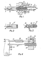
- Fig. 1 shows part of a clutch-control mechanism near its force-input end, i.e. at the end where the pedal or other clutch-actuating member (not shown) is located.
- the mechanism incorporates a Bowden-type control cable of pull type via which force applied to the actuating member is transmitted along a curved path.
- the cable comprises a core 1 slidable with a guiding conduit 2.
- the core is connected at what in the aspect of the figure it its left-hand end to the actuating member.
- the other end of the core is connected to a clutch- release lever.
- the conduit 2 In order that this transmission of clutch releasing force can take place the conduit 2 must be anchored against displacement with the core. At or near its right-hand end (not shown) the conduit is secured to a fixture against axial displacement relative thereto. Near its illustrated end, the conduit is connected to a fixture 4 by means of a releasable coupling hereafter described.
- a tubular abutment 5 is secured to the fixture 4, which may for example be a bulkhead of the vehicle engine compartment.
- the abutment 5 has a spigot 6 which is accommodated in a recess 7 surrounding a hole 8 in the fixture.
- the spigot can for example be a force-fit in such recess or the spigot and recess can be threaded for screw connection.
- the abutment is fitted with an end plug 9 which provides a bearing face for a compression spring 10 the other end of which bears against an annular flange on a ring 11 which is swaged onto the conduit 2.
- the spring 10 serves to hold the conduit under a light tension and to take up any slack.
- the plug 9 also serves as a stop limiting the free play of the device 13.
- a generally tubular component 13 surrounds the illustrated end portion of the conduit and part of the projecting end portion of the core 1.
- An end part 14 of this device 13 is enlarged and is shaped with a frusto-conical face 15 which opposes a frusto-conical face 16 of similar cone angle on the inside of the abutment 5.
- the smaller diameter part of the said tubular component 13 projects from the abutment and extends beyond the adjacent end of the conduit 2.
- the free end portion of the smaller diameter part is formed with a longitudinally curved passageway 12 of such cross-sectional size that it obliges the surrounded portion of the core 1 to undergo directional changes. In consequence the said free end portion of the conduit anchoring device lightly grips the core.
- the component 13 Once the component 13 has moved axially sufficiently to cause its teeth 17 to intrude between projections 18 on the conduit and flanks of those teeth are in contact with flanks of those projections, the component 13 is blocked against continued movement with the core and the latter continues its movement alone, against the light frictional resistance imposed by its contact with the wall of the curved passageway 12. Following this arrest of the component 13, a further slight radially inward displacement of the enlarged end part 14 of the component 13 takes place which causes it fully to interlock with the projections 18 on the conduit and exert firm clamping pressure on the conduit. The conduit is therefore firmly anchored against displacement during the continued displacement of the core whereby the clutch is released.
- the load on the core imposes compressive loads on the length of the conduit located between its end anchorages and as this compressive load is transmitted to the tubular component 13 and urges it to the left in the Fig. 1 aspect, the load tends to maintain the clamping pressure on the conduit.
- the wedge-clamp form of the device 14 and the interlocking engagement of the device 14 with the conduit combine to make the anchorage of the conduit effective even if the component 13 is subject to some degree of side or abaxial loading tending to skew it within the abutment.
- the component 13 is self-aligning. This component can moreover have some capability of flexure under side loading imposed by the core 1.
- the conduit is therefore then free for axial displacement relative to the abutment 5. If clutch plate wear has occurred during the frictional sliding contact of the clutch plates the control cable will still be subject to some loading by the clutch return spring when the actuating member has reached the limit of its travel and this residual loading wil cause the illustrated end of the conduit 2 to move slightly to the left in the aspect of Fig. 1, relative to the component 13. Automatic adjustment will occur if and when the cumulative wear becomes sufficient to cause each of the teeth 17 to engage the conduit one step (equal to the pitch of the teeth and of the projections 18) further from the end of the conduit when the anchoring device 14 next closes onto the conduit. The effect of such leftward movement is that the effective length of the mechanism is slightly altered to compensate for the wear.
- the projections 18 are convolutions of a thread constituted by parts of a helically wound wire forming or forming part of the wall of the conduit 2 of the control cable.
- the gauge of the wire influences the pitch of the thread which in turn determines the smallest adjustment increment which occurs.
- the tensioning spring which takes up slack is of a variable rate for keeping the tensioning force as constant as possible over the adjustment range of the mechanism.
- one or more springs of leaf or other type alternative to a helical spring 10 can be used if desired.
- the described mechanism can be produced at relatively low cost.
- the tubular component 13 can be a one-piece moulding of a reinforced or unreinforced synthetic polymeric material, e.g. an acetal resin.
- the said component can be a metal component or it can comprise a combination of metal and plastics parts.
- the abutment 5 can likewise be made of synthetic polymeric material or metal.
- the abutment is made of a said synthetic material. It is particularly advantageous, particularly for keeping production costs low, to use synthetic polymeric material for both the component 13 and the abutment 5.
- synthetic polymeric material for both the component 13 and the abutment 5.
- synthetic polymeric material for promoting low frictional restraint to relative sliding movement of these parts it is recommended that they be made of different synthetic polymers. It is very suitable for example to use an abutment 5 of nylon or polypropylene for co-operating with a component 13 made of an acetal resin.
- the core 1 can for example be a covered or uncovered stranded wire cable. It is advantageous for the core to have a plastics coating for contacting the wall of the passageway 12.
- Fig. 2 illustrates an alternative form for the free end of the component 13.
- the free end of the component designated 13'
- leaf spring 20 is fitted to the said component so that it extends along that passageway and exerts a light pressure on the core, holding it pressed against the opposite wall portion of the passageway.
- the passage 17 in Fig. 1 is made straight and of sufficient size to allow passage of the core 1 with clearance, and an inherently curved but elastically deformable tube having a bore of fractionally larger diameter than the core is secured to the end of the component 13 to form an extension of the passageway 17.
- tension is applied to the core it tends to straigthen the said tube and the frictional restraint on movement of the core relative to the tube is thereby reduced.
- Fig. 3 shows the free end portion of another form of the component providing the conduit-anchoring device, designated 13".
- the remainder of the component can be of the same form as the component 13 in Fig. 1.
- the tubular stem of the component is formed with a short end-spigot 21 with an integral radial flange 22.
- a extension piece 23 made of a synthetic elastomer is formed to fit onto that spigot and interlock with the flange 22.
- the extension piece has a core-guiding passageway which has three locally enlarged zones 24, each shaped to accommodate a bead 25 which is swaged or otherwise secured to the core 1 of the control cable.
- Fig. 2 illustrates the parts in the relative positions which they occupy in the rest position of the control.
- the component 13" moves with the core by virtue of the location of the bead 25 in one of the accommodating zones 24 in the extension piece 23.
- the extension piece becomes deformed by the pressure exerted by the bead 25 so that the bead escapes from the extension piece.
- the pedal or other actuating member approaches its rest position during the subsequent clutch-engaging stroke of the mechanism the bead 25 re-enters the extension piece and pushes the component out of conduit anchoring position as soon as the residual compressive load on the control cable conduit falls below the force exerted on the extension piece 23 by the bead 25.
- the purpose of providing three accommodating zones 24 for the bead is to allow alternative initial settings of the mechanism.
- the mechanism can accommodate imself by movement of the bead into one or the other of the zones 24, to vehicle body or other installation build tolerances. During the repetitive operations of the control the bead will always return to -the zone 24 in which it was initially located.
- the control cable in the mechanism shown in this figure comprises a core 26 and a guiding conduit 27 having over at least a part of its length an external toothed profile.
- the illustrated end portion of the conduit extends through an aperture 28 in a fixed abutment 29.
- This abutment may for example be a bulkhead forming part of an engine compartment structure.
- the core is connected to a clutch plate lever and the conduit is anchored to another fixture.
- the core is connected to a clutch pedal arm 30 shown in its rest position. When the pedal is depressed to release the clutch against the action of its return spring the arm 30 pivots about axis 31 in the direction of arrow 32, so applying a pull force to the core 26.
- a conduit-anchoring device comprising a pawl 34 is housed.
- the pawl is rockable about a pin 35 against the force exerted by a torsion spring 36 which urges the pawl into its illustrated inoperative position.
- the pawl is connected to the pedal arm 30 by a wire linkage 37 incorporating a tension spring 38.
- the spring 38 is very advantageous for the spring 38 to be of variable rate for avoiding or minimising increases in its resistance to the pedal movement over the pedal movement range.
- one or more springs of leaf or other type can be used as an alternative to the helical spring.
- Fig. 5 illustrates a modified form of the mechanism shown in Fig. 4. Corresponding parts in the two figures are denoted by the same reference numerals.
- a recess 41 just wide enough to accommodate a wedge 42 and seve as a guideway for this wedge in its lateral movements in the plane of the drawing.
- the sloped top face of the wedge co-operates with a cylindrical stop 43 fixed in the recess 41.
- the wedge 42 is connected to a wire 44 which makes a close sliding fit in a hole 45 formed in a wall portion of the abutment 29. The wall of this hole supports the wire 44 so that in the illustrated axial position of the wire the wedge 42 is out of engagement with the conduit 27.
- the end of wire 44 remote from the wedge is pivotally connected to a rigid bar 46 which extends through the upper end portion of the pedal arm 30, which is forked for that purpose.
- a catch device 47 through which the bar 46 is slidable and which is pivotally connected to the pedal arm so that the orientation of the catch device relative to the arm can alter to suit the changing direction of the bar 46 during the rocking of the pedal arm.
- the bar 46 has an indent which in the illustrated position of the parts is engaged by a ball 48 - housed in the catch device 47. The ball is biased towards the bar by a spring 49.
- the stop 43 could be a rotatably mounted roller.
- The. cable control of the mechanism according to Fig. 5 is maintained under a light tension which ensures take-up of slack. This tensioning force can be exerted by a compression spring acting between the abutment 29 and the conduit or at some other part of the system.
- Fig. 6 shows an example of how the invention can be embodied in a push-type control.
- the control cable comprises a core 50 and a conduit 51.
- the core is of a construction permitting it to transmit the necessary compressive loads, while the conduit must be capable of resisting extension under the tensile reaction forces. Suitable constructions of push-type flexible remote control cables are well known per se.
- the end portion of the core at the force input end (which is to the left in the aspect of Fig. 6) can be formed by a rigid rod so that the part of the core which is unsupported by the guiding conduit during an operating cycle is resistant to buckling under heavy load.
- An abutment 52 is secured in a fixture 53.
- the abutment houses wedges 54 which form parts of a component 55 and which have teeth for interlocking with toothed profile of the conduit 51.
- Two wedges are apparent in the drawing. There may be more than two wedges if required, angularly spaced around the conduit.
- the wedges are carried by elastically flexible arms 56 projecting from a hub portion 56 at the extremity of the component 55.
- This hub portion has a bore in which the core 50 is lightly gripped.
- the frictional engagment of the core by the hub portion is sufficiently strong to ensure that the component 55 accompanies the core in the initial part of its movement in the direction of arrow 57 responsive to a push load applied via the pedal or other clutch actuating member.
- the cable control is maintained under a light compressive force by a tension spring 59 one end of which is held in a helical groove in the abutment 52 and the other end of which is held in a helical groove in a cap 60.
- the spring keeps the cap pressed against a collar 61 secured to the conduit.
- Figs. 7 to 9 show three of many possible toothed conduit profiles which can be achieved by helically winding a wire or a pair of wires.
- the profile shown in Fig. 7 is formed by helically winding a single wire 61 of a trapezoidal cross- section such that the teeth have thrust faces 62 substantially normal to the axis of the conduit.
- the wire 63 used for forming the conduit shown in Fig. 8 has a cross section such that the teeth have raked thrust faces 64.
- the conduit represented in Fig. 9 is formed by helically winding two wires 65 and 66.
- a mechanism according to the invention can of course combine features embodied in different illustrated embodiments.
- a stop or pin similar to stop 43 in Fig. 5 can be used to co-operate with a tubular conduit-anchoring device as shown in Fig. 1;
- a conduit-anchoring device comprising a pivoted pawl like pawl 34 in Fig. 4 can be connected to a part is formed to engage with the core solely by friction;
- a conduit-anchoring device which grips the conduit by wedge action like the part 14 in Fig. 1 can be connected indirectly to the core, e.g. via the pedal or other actuating member, by means of an extensible linkage like linkage 37 in Fig. 4.
- the flexible control cable used in carrying out the invention can if desired be of a form, known per se, wherein the core is formed by a flat metal strip supported by caged bearings within the guiding conduit.
- a control cable of a more common form comprising a long-lay stranded wire core, the long-lay wire bundle being bound together by a wrapping wire or strip in the case that the core is to transmit push loads.
Abstract
Claims (15)
Priority Applications (1)
| Application Number | Priority Date | Filing Date | Title |
|---|---|---|---|
| AT83902897T ATE40451T1 (de) | 1982-09-14 | 1983-09-14 | Selbstnachstellende kupplungsvorrichtung. |
Applications Claiming Priority (2)
| Application Number | Priority Date | Filing Date | Title |
|---|---|---|---|
| GB8226107 | 1982-09-14 | ||
| GB8226107 | 1982-09-14 |
Publications (2)
| Publication Number | Publication Date |
|---|---|
| EP0118520A1 EP0118520A1 (fr) | 1984-09-19 |
| EP0118520B1 true EP0118520B1 (fr) | 1989-01-25 |
Family
ID=10532883
Family Applications (1)
| Application Number | Title | Priority Date | Filing Date |
|---|---|---|---|
| EP83902897A Expired EP0118520B1 (fr) | 1982-09-14 | 1983-09-14 | Mecanisme d'embrayage auto-reglable |
Country Status (6)
| Country | Link |
|---|---|
| US (1) | US4717004A (fr) |
| EP (1) | EP0118520B1 (fr) |
| JP (1) | JPS59501722A (fr) |
| AU (1) | AU573536B2 (fr) |
| DE (1) | DE3379072D1 (fr) |
| WO (1) | WO1984001196A1 (fr) |
Families Citing this family (19)
| Publication number | Priority date | Publication date | Assignee | Title |
|---|---|---|---|---|
| GB8400134D0 (en) * | 1984-01-05 | 1984-02-08 | Hoyle E | Cable control operated clutch mechanism |
| GB2157789A (en) * | 1984-01-19 | 1985-10-30 | Bowden Controls Ltd | Self-adjusting clutch control mechanism |
| US4753886A (en) * | 1984-08-10 | 1988-06-28 | Eli Lilly And Company | Plasmid PHJL210 and related bifunctional cloning vectors for use in streptomycetes |
| FR2573158B1 (fr) * | 1984-11-14 | 1987-01-23 | Bendix France | Dispositif de commande mecanique a cable a reglage automatique |
| FR2577330B1 (fr) * | 1985-02-13 | 1987-02-20 | Bendix France | Dispositif de commande mecanique a cable a reglage automatique |
| GB8507803D0 (en) * | 1985-03-26 | 1985-05-01 | Bowden Controls Ltd | Self-adjusting clutch control mechanism |
| FR2589206B1 (fr) * | 1985-10-25 | 1988-04-08 | Bendix France | Dispositif de commande mecanique a cable a reglage manuel |
| US4869123A (en) * | 1985-11-18 | 1989-09-26 | Ford Motor Company | Cable length self-locking adjustment device |
| JPS62209210A (ja) * | 1986-03-07 | 1987-09-14 | Nippon Cable Syst Inc | 操作用ワイヤの張力調節装置 |
| US4798100A (en) * | 1987-09-18 | 1989-01-17 | Babcock Industries Inc. | Automatic adjustment device for cable control systems |
| ES2005638A6 (es) * | 1987-10-09 | 1989-03-16 | Pujol & Tarago | Dispositivo autorregulador de la longitud de cables de embrague. |
| GB2214257B (en) * | 1988-01-25 | 1992-03-18 | Edgar Hoyle | A vehicle braking system |
| GB2260588A (en) * | 1991-10-09 | 1993-04-21 | Rover Group | A clutch cable adjuster |
| ES2128254B1 (es) | 1997-03-25 | 1999-12-16 | Fico Cables Sa | Terminal con dispositivo de fijacion para cables de mando. |
| US5946978A (en) * | 1997-11-13 | 1999-09-07 | Shimano Inc. | Cable adjustment device |
| NL1010929C2 (nl) * | 1998-12-30 | 2000-07-03 | Bernardus Johannes Maria Olde | Zelfcentrerende reminrichting. |
| US6386338B1 (en) * | 2000-12-01 | 2002-05-14 | Dura Global Technologies, Inc. | Electric parking brake manual override |
| FR2968049B1 (fr) * | 2010-11-29 | 2013-09-20 | Peugeot Citroen Automobiles Sa | Dispositif de reglage pour commande mecanique par cable, commande de debrayage et vehicule automobile incorporant ce dispositif |
| RU176060U1 (ru) * | 2017-03-31 | 2017-12-27 | Общество с ограниченной ответственностью "Автопартнер" | Трос привода ручного тормоза |
Family Cites Families (9)
| Publication number | Priority date | Publication date | Assignee | Title |
|---|---|---|---|---|
| US2187636A (en) * | 1938-05-16 | 1940-01-16 | Cleveland Tractor Co | Wear compensating device |
| GB1409527A (en) * | 1971-07-08 | 1975-10-08 | Bowden Controls Ltd | Transmission mechanisms |
| FR2278982A1 (fr) * | 1974-03-19 | 1976-02-13 | Huret Roger | Dispositif de rattrapage du jeu dans une transmission par cable |
| JPS5223129A (en) * | 1975-08-14 | 1977-02-21 | Nippon Zeon Co | Moistureereducing agent for cement compound |
| JPS5432099U (fr) * | 1977-08-06 | 1979-03-02 | ||
| FR2420164A1 (fr) * | 1978-03-17 | 1979-10-12 | Ferodo Sa | Dispositif compensateur pour tringlerie de transmission |
| FR2470994A1 (fr) * | 1979-12-07 | 1981-06-12 | Dba | Commande mecanique par cable coulissant axialement dans une gaine flexible |
| US4344518A (en) * | 1980-09-22 | 1982-08-17 | Acco Industries Inc. | Self-adjusting cable conduit mechanism |
| FR2496197A1 (fr) * | 1980-12-11 | 1982-06-18 | Dba | Commande mecanique par cable coulissant axialement dans une gaine flexible |
-
1983
- 1983-09-14 AU AU19499/83A patent/AU573536B2/en not_active Ceased
- 1983-09-14 WO PCT/GB1983/000225 patent/WO1984001196A1/fr not_active Application Discontinuation
- 1983-09-14 DE DE8383902897T patent/DE3379072D1/de not_active Expired
- 1983-09-14 JP JP58502967A patent/JPS59501722A/ja active Pending
- 1983-09-14 EP EP83902897A patent/EP0118520B1/fr not_active Expired
-
1986
- 1986-10-16 US US06/920,894 patent/US4717004A/en not_active Expired - Fee Related
Also Published As
| Publication number | Publication date |
|---|---|
| WO1984001196A1 (fr) | 1984-03-29 |
| US4717004A (en) | 1988-01-05 |
| JPS59501722A (ja) | 1984-10-11 |
| EP0118520A1 (fr) | 1984-09-19 |
| AU573536B2 (en) | 1988-06-16 |
| AU1949983A (en) | 1984-04-04 |
| DE3379072D1 (en) | 1989-03-02 |
Similar Documents
| Publication | Publication Date | Title |
|---|---|---|
| EP0118520B1 (fr) | Mecanisme d'embrayage auto-reglable | |
| US4690262A (en) | Clutch control cable with auto-adjuster | |
| US4304322A (en) | Compensating device for a transmission linkage | |
| EP0286269B1 (fr) | Ensemble de commande Bowden | |
| US4694706A (en) | Control cable conduit length adjustment device | |
| US4658668A (en) | Transmission kickdown cable adjuster | |
| US4598809A (en) | Cable-and-sleeve connector | |
| EP0120616B1 (fr) | Connexion de câble et de manchon | |
| US4798100A (en) | Automatic adjustment device for cable control systems | |
| GB2187528A (en) | Automatic tension regulating device for remote control wire | |
| US4753123A (en) | Automatic self adjusting cable control device | |
| US4955252A (en) | Cable-and-sleeve connections | |
| EP0619437B1 (fr) | Dispositif d'auto-ajustement de la longueur de cables de commande | |
| CA1233092A (fr) | Telecommande auto-regulatrice a resistance initiale reduite | |
| US3429197A (en) | Motion transmitting remote control assembly | |
| US5139126A (en) | Control device for a clutch, in particular for an automotive vehicle | |
| US20060179965A1 (en) | Contrivance for automatic rope length correction | |
| GB2157789A (en) | Self-adjusting clutch control mechanism | |
| EP0370685B1 (fr) | Dispositif d'ajustage de câble | |
| EP0234864B1 (fr) | Dispositif de réglage pour câble de commande | |
| WO1986005849A1 (fr) | Cable de commande d'embrayage auto-reglable | |
| GB1579840A (en) | Flexible remote control mechanism | |
| US6345702B1 (en) | Brake adjusters | |
| GB2215801A (en) | Cable control mechanism | |
| WO1994018462A1 (fr) | Montage de cable a reglage automatique |
Legal Events
| Date | Code | Title | Description |
|---|---|---|---|
| PUAI | Public reference made under article 153(3) epc to a published international application that has entered the european phase |
Free format text: ORIGINAL CODE: 0009012 |
|
| 17P | Request for examination filed |
Effective date: 19840605 |
|
| AK | Designated contracting states |
Designated state(s): AT BE CH DE FR GB LI LU NL SE |
|
| GRAA | (expected) grant |
Free format text: ORIGINAL CODE: 0009210 |
|
| AK | Designated contracting states |
Kind code of ref document: B1 Designated state(s): AT BE CH DE FR GB LI LU NL SE |
|
| PG25 | Lapsed in a contracting state [announced via postgrant information from national office to epo] |
Ref country code: SE Effective date: 19890125 Ref country code: NL Effective date: 19890125 Ref country code: BE Effective date: 19890125 Ref country code: AT Effective date: 19890125 |
|
| REF | Corresponds to: |
Ref document number: 40451 Country of ref document: AT Date of ref document: 19890215 Kind code of ref document: T |
|
| REF | Corresponds to: |
Ref document number: 3379072 Country of ref document: DE Date of ref document: 19890302 |
|
| ET | Fr: translation filed | ||
| REG | Reference to a national code |
Ref country code: CH Ref legal event code: PL |
|
| NLV1 | Nl: lapsed or annulled due to failure to fulfill the requirements of art. 29p and 29m of the patents act | ||
| PG25 | Lapsed in a contracting state [announced via postgrant information from national office to epo] |
Ref country code: LU Free format text: LAPSE BECAUSE OF NON-PAYMENT OF DUE FEES Effective date: 19890930 Ref country code: LI Free format text: LAPSE BECAUSE OF NON-PAYMENT OF DUE FEES Effective date: 19890930 Ref country code: CH Free format text: LAPSE BECAUSE OF NON-PAYMENT OF DUE FEES Effective date: 19890930 |
|
| PLBI | Opposition filed |
Free format text: ORIGINAL CODE: 0009260 |
|
| 26 | Opposition filed |
Opponent name: ACCO CABLE CONTROLS LTD., Effective date: 19891024 |
|
| PGFP | Annual fee paid to national office [announced via postgrant information from national office to epo] |
Ref country code: GB Payment date: 19910809 Year of fee payment: 9 |
|
| PGFP | Annual fee paid to national office [announced via postgrant information from national office to epo] |
Ref country code: FR Payment date: 19910906 Year of fee payment: 9 |
|
| PGFP | Annual fee paid to national office [announced via postgrant information from national office to epo] |
Ref country code: DE Payment date: 19910930 Year of fee payment: 9 |
|
| RDAG | Patent revoked |
Free format text: ORIGINAL CODE: 0009271 |
|
| STAA | Information on the status of an ep patent application or granted ep patent |
Free format text: STATUS: PATENT REVOKED |
|
| 27W | Patent revoked |
Effective date: 19920629 |
|
| GBPR | Gb: patent revoked under art. 102 of the ep convention designating the uk as contracting state | ||
| REG | Reference to a national code |
Ref country code: CH Ref legal event code: PL |
|
| APAH | Appeal reference modified |
Free format text: ORIGINAL CODE: EPIDOSCREFNO |