EP0117253A1 - Cylindrical piezoelectric vibrator - Google Patents
Cylindrical piezoelectric vibrator Download PDFInfo
- Publication number
- EP0117253A1 EP0117253A1 EP83902697A EP83902697A EP0117253A1 EP 0117253 A1 EP0117253 A1 EP 0117253A1 EP 83902697 A EP83902697 A EP 83902697A EP 83902697 A EP83902697 A EP 83902697A EP 0117253 A1 EP0117253 A1 EP 0117253A1
- Authority
- EP
- European Patent Office
- Prior art keywords
- piezo
- electric
- cylindrical
- vibrating plate
- electric vibrating
- Prior art date
- Legal status (The legal status is an assumption and is not a legal conclusion. Google has not performed a legal analysis and makes no representation as to the accuracy of the status listed.)
- Withdrawn
Links
Images


Classifications
-
- H—ELECTRICITY
- H03—ELECTRONIC CIRCUITRY
- H03H—IMPEDANCE NETWORKS, e.g. RESONANT CIRCUITS; RESONATORS
- H03H9/00—Networks comprising electromechanical or electro-acoustic devices; Electromechanical resonators
- H03H9/02—Details
- H03H9/05—Holders; Supports
- H03H9/10—Mounting in enclosures
- H03H9/1007—Mounting in enclosures for bulk acoustic wave [BAW] devices
- H03H9/1014—Mounting in enclosures for bulk acoustic wave [BAW] devices the enclosure being defined by a frame built on a substrate and a cap, the frame having no mechanical contact with the BAW device
Definitions
- the present invention relates to a piezo-electric resonator having a piezo-electric vibrating plate incorpo rated into a sealed container.
- reference numeral 1 designates a piezo-electric vibrating plate, 2 a hermetic base, 2 1 a metal portion thereof, 2 2 glass portions thereof, 3 a cap, 4 lead lines and 5 conductive bonding agents.
- the materials of the metal portion 2 1 of the hermetic base and the cap 3 are iron, new silver, copper, Kovar and the like.
- the lead lines 4 are led out through the glass portions 2 2 of the hermetic base from the inside of the container to its outside.
- the lead lines are electrically connected to electrodes of the piezo-electric vibrating plate 1 within the container.
- the hermetic base 2 and the cap 3 are connected to each other by soldering or cold press.
- Such prior art piezo-electric resonator requires much material cost and time so that the price thereof becomes high. Also the conventional piezo-electric resonator requires much manual labor and is poor in mass-productivity and can not be mounted automatically.
- the present invention is to provide a piezo- electric resonator which can obviate all the defects inherent in the prior art piezo-electric resonator.
- a piezo- electric vibrating plate is incorporated into a cylindrical container having an insulative property and both ends of this container are sealed by metal caps to thereby use the metal caps as electrodes of the piezo-electric vibrating plate.
- the electrical connection between the piezo-electric vibrating plate and the metal caps is carried out by conductive bonding agents or resilient conductive pieces.
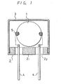
- Fig. 1 is a partially cross-sectional diagram showing a prior art example
- Fig. 2 is a diagram showing an embodiment of the present invention in which Fig. 2A is an exploded perspective diagram of a piezo-electric vibrating portion thereof, Fig. 2 B is a partially cross-sectional diagram of a piezo- electric resonator thereof and Fig. 2C is a cross-sectional diagram taken along a line X-X in Fig. 2B.
- reference numeral 6 generally designates a piezo-electric vibrating portion
- 6 1 designates a piezo-electric vibrating plate
- 6 2 an insulative support plate which supports the piezo-electric vibrating plate 6 1 .
- the piezo-electric vibrating plate 6 1 is so formed to have a shape which is easily incorporated into a cylindrical container (the rectangular shape in the illustrative example).
- the insulative support plate 6 2 has the similar shape to the former but the length and width thereof are selected somewhat larger than those of the piezo-electric vibrating plate 6 1 .
- the insulative support plate 6 2 is made of ceramics material, glass or the like and the both ends of which are metalized.
- Reference numeral 6 3 designate the metalized portions.
- the piezo-electric vibrating plate 6 1 is located on the insulative support plate 6 2 and the piezo- electric vibrating platew 6 1 is fixed at its both ends to the above metalized portions 6 3 by conductive bonding agents 5 1 (see Fig. 2B).
- piezo-electric vibrating plate 6 1 Even if the piezo-electric vibrating plate 6 1 is bonded through the metalized layers 6 3 to the insulative support plate 6 2 , there is provided a small spacing between the piezo-electric vibrating plate 6 1 and the support plate 6 2 so that no influence is exerted on the vibration of the piezo-electric vibrating plate 6 1 .
- Such combined member is called a piezo-electric vibrating portion for convenience.
- Reference numeral 7 designates a cylindrical container (the trunk form in the illustrative example) which is formed of an insulative material such as ceramics, plastic resin, glass or the like. Such cylindrical container of insulating property is low in material cost and can be produced at low prices.
- the both ends of the cylindrical container 7 is metalized continuously from the inner peripheral surface to the external peripheral surface thereof.
- Reference numeral 7 1 designates such a metalized portion. Then, the above piezo-electric vibrating portion 6 is inserted into the cylindrical container 7 and bonded thereto by the conductive bonding agent 5 2 .
- the inner diameter and the length of the cylindrical container 7 are selected to be approximately the same as the width and length of the piezo-electric vibrating portion 6.
- metal caps 8 are pressedly fitted to the both ends of the cylindrical container 7 and heated, if necessary.
- the inner peripheral surfaces of the metal cap 8 and the metalized portions 7 1 of the cylindrical container 7 are closely connected to each other to enable the inside of the cylindrical container to be kept in air tight. If necessary, coating material is applied thereto.
- Each of the metal caps 8 is electrically connected through the metalized portion 7 1 the conductive bonding agent 5 2 , the metalized portion 6 3 and the conductive bonding agent 5 1 tc the piezc-electric vibrating plate 6 1 to serve as the electrode.
- the lead lines are connected to the metal caps. When the metal caps 8 are soldered to tip electrodes and then used as tip parts, it is not necessary to connect the lead lines.
- F ig. 3 is a partially cross-sectional diagram showing another embodiment of the present invention.
- the piezo-electric vibrating portion 6 is formed in the same way as the preceding embodiment but the method to electrically connect the metal caps 8 to the metalized portion 6 3 of the piezo-electric vibrating portion 6 is different from the former.
- Reference numeral 9 designates a resilient conductive piece which is formed by approprietely bending a metal piece.
- a lead line 10 is connected to the metal cap 8 and various ways of connecting the lead line 10 to the metal cap can be considered. For example, the connection can be carried out by soldering. Moreover, it is also possible to connect the lead line 10 to the metal cap 8 in advance.
- Fig. 4 is a diagram showing the appearence of the piezo-electric resonator with the lead line connected thereto according to the present invention
- Fig. 5 is a diagram showing the appearance of the piezo-electric resonator with no lead line connected thereto according to the present invention.
- the cylindrical container is formed of the insulative material
- the above material has insulating property at least on its surface.
- a material for example, metal aluminium with an insulative coating formed on its surface by alumite-treating can be used for making the cylindrical container of the present invention.
- the piezo-electric vibrating plate 6 is formed to be rectangular in shape, the piezo-electric vibrating plate can be formed to be square or circular shape in some case. In that case, it is possible that the metal cap 8 and the piezo-electric vibrating plate 6 1 are electrically connected to each other in the same way.
- the cylindrical piezo- electric resonator according to the present invention has the following remarkable usefulness.
Abstract
Description
- The present invention relates to a piezo-electric resonator having a piezo-electric vibrating plate incorpo rated into a sealed container.
- Almost all of conventional piezo-electric resonator are constructed as shown in Fig. 1. In Fig. 1, reference numeral 1 designates a piezo-electric vibrating plate, 2 a hermetic base, 21 a metal portion thereof, 22 glass portions thereof, 3 a cap, 4 lead lines and 5 conductive bonding agents. The materials of the
metal portion 21 of the hermetic base and thecap 3 are iron, new silver, copper, Kovar and the like. Thelead lines 4 are led out through theglass portions 22 of the hermetic base from the inside of the container to its outside. The lead lines are electrically connected to electrodes of the piezo-electric vibrating plate 1 within the container. Thehermetic base 2 and thecap 3 are connected to each other by soldering or cold press. Such prior art piezo-electric resonator requires much material cost and time so that the price thereof becomes high. Also the conventional piezo-electric resonator requires much manual labor and is poor in mass-productivity and can not be mounted automatically. - The present invention is to provide a piezo- electric resonator which can obviate all the defects inherent in the prior art piezo-electric resonator.
- According to the present invention, a piezo- electric vibrating plate is incorporated into a cylindrical container having an insulative property and both ends of this container are sealed by metal caps to thereby use the metal caps as electrodes of the piezo-electric vibrating plate. The electrical connection between the piezo-electric vibrating plate and the metal caps is carried out by conductive bonding agents or resilient conductive pieces.
- Fig. 1 is a partially cross-sectional diagram showing a prior art example; Fig. 2 is a diagram showing a first embodiment of the present invention in which Fig. 2A is an exploded perspective diagram of a piezo-electric vibrating portion thereof, Fig. 2B is a partially cross-sectional diagram of its piezo-electric resonator and Fig. 2C is a cross-sectional diagram taken along a line X - X in Fig. 2B;'Fig. 3 is a partially cross-sectional diagram showing a second embodiment of the present invention; Fig. 4 is a diagram showing the present invention with a lead line; and Fig. 5 is a diagram showing the appearance of the present invention without the lead line.
- Fig. 2 is a diagram showing an embodiment of the present invention in which Fig. 2A is an exploded perspective diagram of a piezo-electric vibrating portion thereof, Fig. 2B is a partially cross-sectional diagram of a piezo- electric resonator thereof and Fig. 2C is a cross-sectional diagram taken along a line X-X in Fig. 2B. In Fig. 2A,
reference numeral 6 generally designates a piezo-electric vibrating portion,61 designates a piezo-electric vibrating plate and 62 an insulative support plate which supports the piezo-electric vibrating plate 61. The piezo-electricvibrating plate 61 is so formed to have a shape which is easily incorporated into a cylindrical container (the rectangular shape in the illustrative example). Theinsulative support plate 62 has the similar shape to the former but the length and width thereof are selected somewhat larger than those of the piezo-electric vibratingplate 61. Theinsulative support plate 62 is made of ceramics material, glass or the like and the both ends of which are metalized.Reference numeral 63 designate the metalized portions. The piezo-electric vibratingplate 61 is located on theinsulative support plate 62 and the piezo- electric vibratingplatew 61 is fixed at its both ends to the above metalizedportions 63 by conductive bonding agents 51 (see Fig. 2B). Even if the piezo-electric vibratingplate 61 is bonded through themetalized layers 63 to theinsulative support plate 62, there is provided a small spacing between the piezo-electric vibratingplate 61 and thesupport plate 62 so that no influence is exerted on the vibration of the piezo-electric vibrating plate 61. Such combined member is called a piezo-electric vibrating portion for convenience. - In Fig. 2B, like parts corresponding to those in Fig. 2A are marked the same references.
Reference numeral 7 designates a cylindrical container (the trunk form in the illustrative example) which is formed of an insulative material such as ceramics, plastic resin, glass or the like. Such cylindrical container of insulating property is low in material cost and can be produced at low prices. The both ends of thecylindrical container 7 is metalized continuously from the inner peripheral surface to the external peripheral surface thereof.Reference numeral 71 designates such a metalized portion. Then, the above piezo-electric vibratingportion 6 is inserted into thecylindrical container 7 and bonded thereto by theconductive bonding agent 52. To this end, it is desired that the inner diameter and the length of thecylindrical container 7 are selected to be approximately the same as the width and length of the piezo-electric vibratingportion 6. Then,metal caps 8 are pressedly fitted to the both ends of thecylindrical container 7 and heated, if necessary. Thus, the inner peripheral surfaces of themetal cap 8 and themetalized portions 71 of thecylindrical container 7 are closely connected to each other to enable the inside of the cylindrical container to be kept in air tight. If necessary, coating material is applied thereto. Each of themetal caps 8 is electrically connected through themetalized portion 71 theconductive bonding agent 52, themetalized portion 63 and theconductive bonding agent 51 tc the piezc-electricvibrating plate 61 to serve as the electrode. If necessary, the lead lines are connected to the metal caps. When themetal caps 8 are soldered to tip electrodes and then used as tip parts, it is not necessary to connect the lead lines. - Fig. 3 is a partially cross-sectional diagram showing another embodiment of the present invention. In the figure, like parts corresponding to those in Fig. 2 are marked with the same references. In this embodiment, the piezo-electric vibrating
portion 6 is formed in the same way as the preceding embodiment but the method to electrically connect themetal caps 8 to themetalized portion 63 of the piezo-electric vibratingportion 6 is different from the former. Reference numeral 9 designates a resilient conductive piece which is formed by approprietely bending a metal piece. When this resilient conductive piece is inserted into themetal cap 8 which then is pressedly fitted into each of both ends of thecylindrical container 7, themetal cap 8 is electrically connected through the resilient conductive piece 9, the metalizedportion 63 and theconductive bonding agent 51 to the piezo-electric vibratingplate 61. As is shown in the figure, alead line 10 is connected to themetal cap 8 and various ways of connecting thelead line 10 to the metal cap can be considered. For example, the connection can be carried out by soldering. Moreover, it is also possible to connect thelead line 10 to themetal cap 8 in advance. - Fig. 4 is a diagram showing the appearence of the piezo-electric resonator with the lead line connected thereto according to the present invention, while Fig. 5 is a diagram showing the appearance of the piezo-electric resonator with no lead line connected thereto according to the present invention.
- While in the above; embodiments the cylindrical container is formed of the insulative material, it is sufficient that the above material has insulating property at least on its surface. For example, a material, for example, metal aluminium with an insulative coating formed on its surface by alumite-treating can be used for making the cylindrical container of the present invention. In addition, while the piezo-electric vibrating
plate 6, is formed to be rectangular in shape, the piezo-electric vibrating plate can be formed to be square or circular shape in some case. In that case, it is possible that themetal cap 8 and the piezo-electricvibrating plate 61 are electrically connected to each other in the same way. - As set forth above, the cylindrical piezo- electric resonator according to the present invention has the following remarkable usefulness.
- (a) Material cost is low and the manufacturing cost can be lowered.
- (b) The cylindrical piezo-electric resonator of the invention is manufactured easily and it is suitable for the mass-production.
- (c) When the cylindrical piezo-electric resonator according to the present invention is mounted on a base or the like, the cylindrical piezo-electric resonator with the lead line connected thereto can automatically be mounted, while the cylindrical piezo-electric resonator with no lead line connected thereto can promote the automatic mounting thereof as tip parts.
Claims (4)
Applications Claiming Priority (2)
| Application Number | Priority Date | Filing Date | Title |
|---|---|---|---|
| JP147227/82 | 1982-08-25 | ||
| JP14722782A JPS5937720A (en) | 1982-08-25 | 1982-08-25 | Cylindrical piezoelectric oscillator |
Publications (2)
| Publication Number | Publication Date |
|---|---|
| EP0117253A1 true EP0117253A1 (en) | 1984-09-05 |
| EP0117253A4 EP0117253A4 (en) | 1986-04-02 |
Family
ID=15425441
Family Applications (1)
| Application Number | Title | Priority Date | Filing Date |
|---|---|---|---|
| EP19830902697 Withdrawn EP0117253A4 (en) | 1982-08-25 | 1983-08-25 | Cylindrical piezoelectric vibrator. |
Country Status (4)
| Country | Link |
|---|---|
| EP (1) | EP0117253A4 (en) |
| JP (1) | JPS5937720A (en) |
| GB (1) | GB2137804A (en) |
| WO (1) | WO1984001064A1 (en) |
Cited By (1)
| Publication number | Priority date | Publication date | Assignee | Title |
|---|---|---|---|---|
| GB2225160A (en) * | 1988-10-04 | 1990-05-23 | Toko Inc | Piezoelectric resonator |
Families Citing this family (2)
| Publication number | Priority date | Publication date | Assignee | Title |
|---|---|---|---|---|
| JPS62258510A (en) * | 1986-05-01 | 1987-11-11 | Murata Mfg Co Ltd | Piezoelectric resonator and its manufacture |
| GB2266806B (en) * | 1992-05-06 | 1996-01-24 | Dowty Maritime Ltd | Piezoelectric device |
Family Cites Families (2)
| Publication number | Priority date | Publication date | Assignee | Title |
|---|---|---|---|---|
| JPS5618012Y2 (en) * | 1974-05-20 | 1981-04-27 | ||
| JPS5648120U (en) * | 1979-09-20 | 1981-04-28 |
-
1982
- 1982-08-25 JP JP14722782A patent/JPS5937720A/en active Pending
-
1983
- 1983-08-25 GB GB08410089A patent/GB2137804A/en not_active Withdrawn
- 1983-08-25 WO PCT/JP1983/000278 patent/WO1984001064A1/en not_active Application Discontinuation
- 1983-08-25 EP EP19830902697 patent/EP0117253A4/en not_active Withdrawn
Non-Patent Citations (1)
| Title |
|---|
| See references of WO8401064A1 * |
Cited By (2)
| Publication number | Priority date | Publication date | Assignee | Title |
|---|---|---|---|---|
| GB2225160A (en) * | 1988-10-04 | 1990-05-23 | Toko Inc | Piezoelectric resonator |
| GB2225160B (en) * | 1988-10-04 | 1993-03-17 | Toko Inc | Piezo-resonator |
Also Published As
| Publication number | Publication date |
|---|---|
| WO1984001064A1 (en) | 1984-03-15 |
| GB2137804A (en) | 1984-10-10 |
| JPS5937720A (en) | 1984-03-01 |
| EP0117253A4 (en) | 1986-04-02 |
| GB8410089D0 (en) | 1984-05-31 |
Similar Documents
| Publication | Publication Date | Title |
|---|---|---|
| KR19980086403A (en) | Electronic components with piezoelectric three-terminal components | |
| US4538205A (en) | Means and method for fabricating planar terminated capacitors | |
| US4496871A (en) | Parallel type piezoelectric bimorph vibrator | |
| KR100405387B1 (en) | Piezoelectric resonator | |
| JP3099382B2 (en) | Small oscillator | |
| EP0117253A1 (en) | Cylindrical piezoelectric vibrator | |
| JPH0134402Y2 (en) | ||
| JPS5931217B2 (en) | Microwave integrated circuit package | |
| JPS6367908A (en) | Electric parts having two-terminal type piezoelectric resonance element and its production | |
| JPS58148510A (en) | Method for forming lead terminal on printed circuit board | |
| JPH09191058A (en) | Surface mount container | |
| JPS5853031Y2 (en) | display panel | |
| JPH0450651Y2 (en) | ||
| JPS62247Y2 (en) | ||
| JPS6020916Y2 (en) | Axial lead capacitor | |
| JPH08139384A (en) | Method of mounting cylindrical piezoelectric transformer | |
| JPH0132330Y2 (en) | ||
| JP3151988B2 (en) | Electronic components for surface mounting | |
| JPS6035233Y2 (en) | variable ceramic capacitor | |
| JPH0311943Y2 (en) | ||
| JPH0351259B2 (en) | ||
| JPH0730360A (en) | Piezoelectric vibration device | |
| JPS59105710A (en) | Cylindrical piezoelectric oscillator | |
| JPS6192019A (en) | Piezoelectric ceramic vibrator | |
| JPH0410610A (en) | Manufacture of lead terminal and electronic parts having the lead terminal |
Legal Events
| Date | Code | Title | Description |
|---|---|---|---|
| PUAI | Public reference made under article 153(3) epc to a published international application that has entered the european phase |
Free format text: ORIGINAL CODE: 0009012 |
|
| 17P | Request for examination filed |
Effective date: 19840628 |
|
| AK | Designated contracting states |
Designated state(s): DE FR |
|
| A4 | Supplementary search report drawn up and despatched |
Effective date: 19860402 |
|
| STAA | Information on the status of an ep patent application or granted ep patent |
Free format text: STATUS: THE APPLICATION IS DEEMED TO BE WITHDRAWN |
|
| 18D | Application deemed to be withdrawn |
Effective date: 19860304 |
|
| RIN1 | Information on inventor provided before grant (corrected) |
Inventor name: SAIGUSA, YASUTAKAFUJI SANGYO KABUSHIKI KAISHA Inventor name: IWASHITA, ISAOFUJI SANGYO KABUSHIKI KAISHA Inventor name: TSUCHIYA, YASUHISAFUJI SANGYO KABUSHIKI KAISHA |