EP0117200B1 - Installation pour la transformation chimique d'un mélange gazeux contenant de l'hydrogène et des hydrocarbures - Google Patents
Installation pour la transformation chimique d'un mélange gazeux contenant de l'hydrogène et des hydrocarbures Download PDFInfo
- Publication number
- EP0117200B1 EP0117200B1 EP84400303A EP84400303A EP0117200B1 EP 0117200 B1 EP0117200 B1 EP 0117200B1 EP 84400303 A EP84400303 A EP 84400303A EP 84400303 A EP84400303 A EP 84400303A EP 0117200 B1 EP0117200 B1 EP 0117200B1
- Authority
- EP
- European Patent Office
- Prior art keywords
- gas mixture
- furnaces
- installation
- furnace
- electric
- Prior art date
- Legal status (The legal status is an assumption and is not a legal conclusion. Google has not performed a legal analysis and makes no representation as to the accuracy of the status listed.)
- Expired
Links
- 239000001257 hydrogen Substances 0.000 title claims abstract description 15
- 229910052739 hydrogen Inorganic materials 0.000 title claims abstract description 15
- 229930195733 hydrocarbon Natural products 0.000 title claims abstract description 14
- UFHFLCQGNIYNRP-UHFFFAOYSA-N Hydrogen Chemical compound [H][H] UFHFLCQGNIYNRP-UHFFFAOYSA-N 0.000 title claims abstract description 13
- 150000002430 hydrocarbons Chemical class 0.000 title claims abstract description 13
- 239000008246 gaseous mixture Substances 0.000 title description 5
- 230000009466 transformation Effects 0.000 title 1
- 238000009434 installation Methods 0.000 claims abstract description 48
- 239000000203 mixture Substances 0.000 claims abstract description 44
- 239000007789 gas Substances 0.000 claims abstract description 38
- 238000006243 chemical reaction Methods 0.000 claims abstract description 13
- 238000011144 upstream manufacturing Methods 0.000 claims abstract description 11
- 238000005485 electric heating Methods 0.000 claims abstract description 4
- 238000003303 reheating Methods 0.000 claims abstract description 4
- 239000000126 substance Substances 0.000 claims abstract 3
- 239000002803 fossil fuel Substances 0.000 claims description 16
- 239000003054 catalyst Substances 0.000 claims description 12
- 238000001833 catalytic reforming Methods 0.000 claims description 5
- 230000000295 complement effect Effects 0.000 claims 1
- 239000012530 fluid Substances 0.000 claims 1
- 238000000034 method Methods 0.000 claims 1
- 238000010438 heat treatment Methods 0.000 description 9
- 239000000446 fuel Substances 0.000 description 5
- BASFCYQUMIYNBI-UHFFFAOYSA-N platinum Chemical compound [Pt] BASFCYQUMIYNBI-UHFFFAOYSA-N 0.000 description 5
- 238000005265 energy consumption Methods 0.000 description 4
- 230000005611 electricity Effects 0.000 description 3
- 238000002485 combustion reaction Methods 0.000 description 2
- 238000006477 desulfuration reaction Methods 0.000 description 2
- 230000023556 desulfurization Effects 0.000 description 2
- 229910052697 platinum Inorganic materials 0.000 description 2
- 239000010779 crude oil Substances 0.000 description 1
- 230000003247 decreasing effect Effects 0.000 description 1
- 238000010586 diagram Methods 0.000 description 1
- 239000010771 distillate fuel oil Substances 0.000 description 1
- 238000004821 distillation Methods 0.000 description 1
- 230000009977 dual effect Effects 0.000 description 1
- 230000000694 effects Effects 0.000 description 1
- 239000000686 essence Substances 0.000 description 1
- 239000003517 fume Substances 0.000 description 1
- 239000010763 heavy fuel oil Substances 0.000 description 1
- 150000002431 hydrogen Chemical class 0.000 description 1
- -1 hydrogen hydrocarbons Chemical class 0.000 description 1
- 239000007788 liquid Substances 0.000 description 1
- 229910052751 metal Inorganic materials 0.000 description 1
- 239000002184 metal Substances 0.000 description 1
- 150000002739 metals Chemical class 0.000 description 1
- TVMXDCGIABBOFY-UHFFFAOYSA-N octane Chemical compound CCCCCCCC TVMXDCGIABBOFY-UHFFFAOYSA-N 0.000 description 1
- 238000013021 overheating Methods 0.000 description 1
- 239000011541 reaction mixture Substances 0.000 description 1
- 238000004064 recycling Methods 0.000 description 1
- 238000002407 reforming Methods 0.000 description 1
- 238000006057 reforming reaction Methods 0.000 description 1
- XLYOFNOQVPJJNP-UHFFFAOYSA-N water Substances O XLYOFNOQVPJJNP-UHFFFAOYSA-N 0.000 description 1
Images

Classifications
-
- C—CHEMISTRY; METALLURGY
- C10—PETROLEUM, GAS OR COKE INDUSTRIES; TECHNICAL GASES CONTAINING CARBON MONOXIDE; FUELS; LUBRICANTS; PEAT
- C10G—CRACKING HYDROCARBON OILS; PRODUCTION OF LIQUID HYDROCARBON MIXTURES, e.g. BY DESTRUCTIVE HYDROGENATION, OLIGOMERISATION, POLYMERISATION; RECOVERY OF HYDROCARBON OILS FROM OIL-SHALE, OIL-SAND, OR GASES; REFINING MIXTURES MAINLY CONSISTING OF HYDROCARBONS; REFORMING OF NAPHTHA; MINERAL WAXES
- C10G35/00—Reforming naphtha
- C10G35/04—Catalytic reforming
-
- C—CHEMISTRY; METALLURGY
- C10—PETROLEUM, GAS OR COKE INDUSTRIES; TECHNICAL GASES CONTAINING CARBON MONOXIDE; FUELS; LUBRICANTS; PEAT
- C10G—CRACKING HYDROCARBON OILS; PRODUCTION OF LIQUID HYDROCARBON MIXTURES, e.g. BY DESTRUCTIVE HYDROGENATION, OLIGOMERISATION, POLYMERISATION; RECOVERY OF HYDROCARBON OILS FROM OIL-SHALE, OIL-SAND, OR GASES; REFINING MIXTURES MAINLY CONSISTING OF HYDROCARBONS; REFORMING OF NAPHTHA; MINERAL WAXES
- C10G49/00—Treatment of hydrocarbon oils, in the presence of hydrogen or hydrogen-generating compounds, not provided for in a single one of groups C10G45/02, C10G45/32, C10G45/44, C10G45/58 or C10G47/00
- C10G49/002—Apparatus for fixed bed hydrotreatment processes
Definitions
- the present invention relates to an installation for the chemical transformation of a gas mixture containing in particular hydrocarbons and hydrogen.
- This installation comprises reactors in which the above-mentioned mixture reacts according to globally endothermic reactions at temperatures between approximately 350 and 900 ° C., under high pressure and in the presence of a catalyst.
- This installation also comprises an oven arranged upstream of each reactor to heat the gas mixture before its introduction into the reactor.
- the furnaces for reheating the gaseous mixture of hydrocarbons and hydrogen are conventional furnaces supplied with liquid or gaseous fuel of fossil origin. These ovens include bundles of tubes of reduced section heated by combustion of fuel of fossil origin, in which the above-mentioned gas mixture is passed.
- the aforementioned flame ovens are bulky mainly depending on the fact that a single ply of tubes surrounds the flame.
- the object of the present invention is to create an installation which overcomes all the aforementioned drawbacks.
- the installation targeted by the invention for the chemical transformation of a gaseous mixture containing in particular hydrogen and hydrocarbons comprises a succession of reactors for reacting the above-mentioned mixture according to globally endothermic reactions at temperatures between 400 and 900 ° C approximately, under high pressure and in the presence of a catalyst.
- An oven is arranged upstream of each reactor to heat the gas mixture before its introduction into said reactor.
- this installation is characterized in that the ovens are constituted by an enclosure comprising an inlet and an outlet of the gas mixture and containing one or more electrical resistance (s) for heating intended to be placed (s) in direct contact with the gas mixture introduced into this enclosure.
- the ovens are constituted by an enclosure comprising an inlet and an outlet of the gas mixture and containing one or more electrical resistance (s) for heating intended to be placed (s) in direct contact with the gas mixture introduced into this enclosure.
- Electric resistance heating furnaces thus replace furnaces supplied with fossil fuel, such as light or heavy fuel oil.
- the installation comprises in parallel with each furnace supplied with fossil fuel an electric furnace constituted by an enclosure comprising a inlet and outlet of the gas mixture and one or more electrical heating resistors intended to be placed in direct contact with the gas mixture introduced into this enclosure, and means for passing the gas mixture at will either through the furnaces supplied with fuel fossil origin, either by electric resistance ovens.
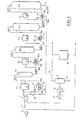
- FIG. 1 schematically represents an installation for the catalytic reforming of naphtha obtained by distillation of crude oil, intended to produce gasolines with a high octane number.
- This installation includes 4 reactors R 1 , R 2 , R 3 , R 4 in which the reforming reactions are carried out between a gaseous mixture of hydrocarbons enriched in hydrogen at temperatures around 500 ° C, pressures between 15 and 30 bars and in the presence of a platinum-based catalyst.
- each reactor R 1 , R 2 , R 3 , R 4 upstream of each reactor R 1 , R 2 , R 3 , R 4 is placed an oven F 1 , F 2 , F 3 , F 4 which makes it possible to preheat the mixture of hydrocarbons and hydrogen to the optimum temperature before this mixture enters the following reactor R 1 , R 2 , R 3 , R 4 .
- the mixture 1 of hydrogen-enriched hydrocarbons is introduced into the first furnace F 1 by means of a pump 2.
- the effluent 3 from the last reactor R 4 passes through heat exchangers 4 disposed upstream of the first furnace F 1 and arranged to carry out a heat exchange between this effluent 3 and the gas mixture 1 which is introduced into the first furnace F 1 .
- This heat exchange makes it possible to preheat the initial gas mixture 1 before it enters the furnace F 1 .
- the effluent 3 after this heat exchange is cooled in an air cooler 5 then in a water cooler 6, before entering a separator flask 7 in which the gas to be recycled is separated from the reformate.
- This reformate is recovered at 8.
- Part of the gas to be recycled 9 coming from the separator 7 is compressed by means of a compressor 10 which re-injects it downstream of the pump 2 to mix it with the starting naphtha.
- the installation comprises, in parallel with each furnace F 1 ′ F z , F 3 , F 4 supplied with fossil fuel, an furnace F 5 , F e , F 7 , F 8 constituted by an enclosure 11, 12, 13, 14 comprising an inlet 15a, 16a, 17a, 18a and an outlet 15b, 16b, 17b, 18b and which contains electrical heating resistors 19, 20, 21, 22.
- These heating resistors 19 to 22 are placed in direct contact with the gas mixture introduced into each of the electric ovens F 5 , F 6 , F 7 , F 8 .
- These electric ovens F 5 , F e , F 7 , F 8 are constructed in such a way that the mixture of hydrogen and hydrocarbons passes through these ovens with a low pressure drop.
- These electric ovens can be in accordance with that described in French patent No. 2,541,436 in the names of the applicants and which is entitled "Electric heating device by direct Joule effect to heat a gas mixture”.
- the installation according to the invention comprises means for passing the gas mixture at will either through conventional ovens F 1 , F 2 , F 3 .
- F 4 supplied with fossil fuel, either by electric resistance furnaces F 5 , F 6 , F 7 , F 8 .
- These means are constituted (see FIGS. 2 and 3) by valves V 1 , V 2 ... V 4 , V5 placed at the inlet and at the outlet of conventional ovens F 1 , ... F 4 and of valves V 6 , V 7 ... V 9 , V 10 placed on the branches 23 ... 27 which extend between the conventional ovens F 1 ... F 4 and the electric ovens F 5 ... F 8 .
- one or more additional heat exchangers 28 are placed on the branch 23 comprised between the outlet 4a of the first exchangers 4 and the inlet 15a of the first electric furnace F 5 .
- These exchangers 28 are arranged to carry out an additional heat exchange between the gas mixture introduced into the first electric furnace F 5 and the gaseous effluent 3 coming from the last reactor R 4 .
- Valves V 11 , V 12 placed upstream and downstream of the exchangers 28 on a circuit 29 connected with that of the effluent 3 and a valve V 13 placed on a bypass circuit 30 directly connected to the first exchangers 4, allow either to passing the effluent 3 through the exchangers 28 during the commissioning of the electric ovens F 5 ... F 8 , either directly and only in the first exchanger 4 during the commissioning of the conventional ovens F 1 ... F 4 .
- the pressure drop caused by the exchanger (s) 28 is less than the reduction in pressure drop achieved during the commissioning of the electric ovens F 5 ... F 8 .
- the reduction in pressure losses provides the installation with a credit for pressure losses which makes it possible to insert into the 'installation, one or more additional exchangers 28 which will allow the initial mixture to be brought by heat exchange with the effluent 3 from the last reactor R 4 at a temperature of 460 ° C or more before entering the first oven F 5 , instead of 427.5 ° when using conventional ovens.
- the invention could include only electric ovens in total replacement of conventional ovens.
- the installation could be specifically adapted to total operation with electric ovens.
- the invention could relate only to a partial replacement of conventional ovens for one or more electric ovens.
- the number of furnaces and reactors could be multiplied by correspondingly decreasing their respective sizes, in order to tend towards a quasi-isothermal temperature profile within the catalyst. This would allow better use of the catalyst, therefore a reduction in the overall volume of catalyst and thus a saving in the supply of catalyst, the cost of which is particularly high since it is based on noble and rare metals.
- this pressure drop credit allows more efficient operation of the installation, in particular better use of the catalyst, by adapting the operating conditions of the unit, thus, for example, the lowering of the average pressure in the installation provides a higher yield of species.
- the invention is applicable in all cases where a high power heating of a mixture of hydrocarbons and hydrogen is carried out under high pressure, upstream of one or more reactors in which the globally endothermic reactions take place. , at temperatures between 350 and 900 ° C approximately.
- the invention can also be applied in particular to installations for the treatment of desulfurization of hydrogen hydrocarbons.
Landscapes
- Chemical & Material Sciences (AREA)
- Oil, Petroleum & Natural Gas (AREA)
- Engineering & Computer Science (AREA)
- Chemical Kinetics & Catalysis (AREA)
- General Chemical & Material Sciences (AREA)
- Organic Chemistry (AREA)
- Hydrogen, Water And Hydrids (AREA)
- Production Of Liquid Hydrocarbon Mixture For Refining Petroleum (AREA)
- Organic Low-Molecular-Weight Compounds And Preparation Thereof (AREA)
- Physical Or Chemical Processes And Apparatus (AREA)
Priority Applications (1)
| Application Number | Priority Date | Filing Date | Title |
|---|---|---|---|
| AT84400303T ATE25100T1 (de) | 1983-02-21 | 1984-02-15 | Einrichtung zur chemischen umsetzung einer wasserstoff und kohlenwasserstoffe enthaltenden gasfoermigen mischung. |
Applications Claiming Priority (2)
| Application Number | Priority Date | Filing Date | Title |
|---|---|---|---|
| FR8302764A FR2541133A1 (fr) | 1983-02-21 | 1983-02-21 | Installation pour la transformation chimique d'un melange gazeux contenant de l'hydrogene et des hydrocarbures |
| FR8302764 | 1983-02-21 |
Publications (2)
| Publication Number | Publication Date |
|---|---|
| EP0117200A1 EP0117200A1 (fr) | 1984-08-29 |
| EP0117200B1 true EP0117200B1 (fr) | 1987-01-21 |
Family
ID=9286101
Family Applications (1)
| Application Number | Title | Priority Date | Filing Date |
|---|---|---|---|
| EP84400303A Expired EP0117200B1 (fr) | 1983-02-21 | 1984-02-15 | Installation pour la transformation chimique d'un mélange gazeux contenant de l'hydrogène et des hydrocarbures |
Country Status (9)
| Country | Link |
|---|---|
| US (1) | US4746495A (https=) |
| EP (1) | EP0117200B1 (https=) |
| JP (1) | JPS59157179A (https=) |
| AT (1) | ATE25100T1 (https=) |
| AU (1) | AU2473284A (https=) |
| CA (1) | CA1231909A (https=) |
| DE (2) | DE3462150D1 (https=) |
| FR (1) | FR2541133A1 (https=) |
| ZA (1) | ZA841124B (https=) |
Families Citing this family (11)
| Publication number | Priority date | Publication date | Assignee | Title |
|---|---|---|---|---|
| US4973453A (en) * | 1988-02-05 | 1990-11-27 | Gtg, Inc. | Apparatus for the production of heavier hydrocarbons from gaseous light hydrocarbons |
| GB2401804B (en) * | 2003-05-19 | 2006-09-27 | Phoenix Chemicals Ltd | Reactor |
| US7906013B2 (en) * | 2006-12-29 | 2011-03-15 | Uop Llc | Hydrocarbon conversion process |
| KR101308510B1 (ko) * | 2007-11-05 | 2013-09-12 | 동부대우전자 주식회사 | 히터 내장형 흡기관을 구비하는 건조기 |
| US9279087B2 (en) * | 2008-06-30 | 2016-03-08 | Uop Llc | Multi-staged hydroprocessing process and system |
| US8999141B2 (en) * | 2008-06-30 | 2015-04-07 | Uop Llc | Three-phase hydroprocessing without a recycle gas compressor |
| US8008534B2 (en) | 2008-06-30 | 2011-08-30 | Uop Llc | Liquid phase hydroprocessing with temperature management |
| CN101424447B (zh) * | 2008-10-07 | 2011-02-02 | 艾欧史密斯(中国)热水器有限公司 | 混合能源恒温控制热水器 |
| US8518241B2 (en) * | 2009-06-30 | 2013-08-27 | Uop Llc | Method for multi-staged hydroprocessing |
| US8221706B2 (en) * | 2009-06-30 | 2012-07-17 | Uop Llc | Apparatus for multi-staged hydroprocessing |
| DK202530282A1 (en) * | 2025-05-06 | 2026-04-23 | Topsoe As | Electrical heating in low carbon processes |
Family Cites Families (10)
| Publication number | Priority date | Publication date | Assignee | Title |
|---|---|---|---|---|
| US1915567A (en) * | 1926-03-23 | 1933-06-27 | Carter Russell | Heating unit for hydrogenous and carbonaceous values recovery |
| US1868096A (en) * | 1929-06-05 | 1932-07-19 | Dreyfus Henry | Manufacture of methyl alcohol |
| US2210257A (en) * | 1939-08-12 | 1940-08-06 | Universal Oil Prod Co | Catalytic conversion of hydrocarbons |
| US2947682A (en) * | 1956-12-03 | 1960-08-02 | Sinclair Refining Co | Method of producing a high octane gasoline by reforming a naphtha in two stages |
| US3128242A (en) * | 1961-06-08 | 1964-04-07 | Socony Mobil Oil Co Inc | Isothermal-adiabatic catalytic hydrocarbon conversion |
| GB1267803A (en) * | 1968-04-03 | 1972-03-22 | Laporte Titanium Ltd | Improvements in and relating to the heating of gases |
| US4166024A (en) * | 1978-07-10 | 1979-08-28 | Exxon Research & Engineering Co. | Process for suppression of hydrogenolysis and C5+ liquid yield loss in a cyclic reforming unit |
| CA1082759A (en) * | 1979-10-12 | 1980-07-29 | Douglas E. Carl | Alternative heating apparatus for use in a heating system having a fuel burner, particularly a forced- air central heating system |
| US4341167A (en) * | 1980-10-29 | 1982-07-27 | St John Eric P | Energy conserving heating and cooling system for printing plant |
| FR2541436A1 (fr) * | 1983-02-21 | 1984-08-24 | Spie Batignolles | Dispositif de chauffage electrique par effet joule direct pour chauffer un melange gazeux |
-
1983
- 1983-02-21 FR FR8302764A patent/FR2541133A1/fr active Granted
-
1984
- 1984-02-15 EP EP84400303A patent/EP0117200B1/fr not_active Expired
- 1984-02-15 CA CA000447444A patent/CA1231909A/en not_active Expired
- 1984-02-15 AT AT84400303T patent/ATE25100T1/de not_active IP Right Cessation
- 1984-02-15 DE DE8484400303T patent/DE3462150D1/de not_active Expired
- 1984-02-15 ZA ZA841124A patent/ZA841124B/xx unknown
- 1984-02-15 DE DE198484400303T patent/DE117200T1/de active Pending
- 1984-02-20 AU AU24732/84A patent/AU2473284A/en not_active Abandoned
- 1984-02-21 JP JP59029668A patent/JPS59157179A/ja active Pending
-
1986
- 1986-03-10 US US06/838,438 patent/US4746495A/en not_active Expired - Fee Related
Also Published As
| Publication number | Publication date |
|---|---|
| FR2541133B1 (https=) | 1985-04-19 |
| ATE25100T1 (de) | 1987-02-15 |
| DE117200T1 (de) | 1984-12-20 |
| DE3462150D1 (en) | 1987-02-26 |
| EP0117200A1 (fr) | 1984-08-29 |
| CA1231909A (en) | 1988-01-26 |
| US4746495A (en) | 1988-05-24 |
| AU2473284A (en) | 1984-08-30 |
| FR2541133A1 (fr) | 1984-08-24 |
| JPS59157179A (ja) | 1984-09-06 |
| ZA841124B (en) | 1984-09-26 |
Similar Documents
| Publication | Publication Date | Title |
|---|---|---|
| EP0117200B1 (fr) | Installation pour la transformation chimique d'un mélange gazeux contenant de l'hydrogène et des hydrocarbures | |
| DE60314432T2 (de) | Festoxidbrennstoffzelle | |
| JP5292389B2 (ja) | 水素システムおよび水素システムの始動方法 | |
| US6977002B2 (en) | Fuel reforming apparatus and the method of starting it | |
| EP2061113B1 (de) | Brennstoffzellensystem und Verfahren zu dessen Betrieb | |
| EA010401B1 (ru) | Способ работы газовой двигательной установки и системы подачи топлива газового двигателя | |
| DE102008045147B4 (de) | Effizientes Brennstoffzellensystem mit integrierter Gaserzeugung und zugehöriges Verfahren zur Regelung und Steuerung des Betriebes | |
| JP2006322454A (ja) | 燃料安定化システムおよび燃料供給システムの燃料安定化方法 | |
| EP0794150B1 (fr) | Procédé et dispositif de craquage de l'ammoniac présent dans un gaz contenant de l'hydrogéne sulfuré | |
| CH700655A1 (fr) | Procede et dispositif de traitement par oxydation par voie humide de dechets liquides contenant des charges en matieres minerales. | |
| JP4873282B2 (ja) | 改質方法および改質器 | |
| DE10104607A1 (de) | Gaserzeugungssystem für ein Brennstoffzellensystem und Verfahren zum Betrieb eines Gaserzeugungssystems | |
| FR2887867A1 (fr) | Installation combinee de production d'energie electrique et de production d'hydrogene | |
| EP1942537B1 (de) | Brennstoffzellensystem mit einer Regenerationseinrichtung für einen Reformer und zugehöriges Verfahren | |
| KR100517953B1 (ko) | 산소를 함유한 가스터어빈의 배기가스를 이용하여 연소실에 연소공기를 공급하는 방법 및 이를 이용한 공정설비 | |
| DE102011116981B4 (de) | Abgasbehandlungssystem zum Behandeln von Abgas von einer Brennkraftmaschine | |
| CA2307069A1 (en) | Water-gas shift reactor warm-up | |
| EP2711334B1 (fr) | Procédé de production d'hydrogène pur à partir d'une charge hydrocarbonée dénaturée incluant une étape de désulfuration avec contrôle de température en amont du PSA | |
| DE19623732A1 (de) | Katalytisches Schwelverfahren für Kunststoffe und Gemischen aus Kunststoffen und organischen Materialien, wie Papier und organischen Ölen, zur Produktion von hochwertigem Brenn- oder Dieselöl | |
| FR2622563A1 (fr) | Procede de reformage de methanol impur et dispositif de mise en oeuvre | |
| FR2831333A1 (fr) | Dispositif d'alimentation en gaz d'une pile a combustible | |
| FR2837810A1 (fr) | Dispositif de conversion d'un flux de matiere contenant des hydrocarbures | |
| FR2994249A1 (fr) | Procede et installation de production d'electricite a partir de dechets fermentescibles, en particuler de boues de station d'epuration | |
| DE202006008898U1 (de) | Brennstoffzellensystem für ein Fahrzeug | |
| WO2006040490A1 (fr) | Generateur d'electricite pour vehicule automobile |
Legal Events
| Date | Code | Title | Description |
|---|---|---|---|
| PUAI | Public reference made under article 153(3) epc to a published international application that has entered the european phase |
Free format text: ORIGINAL CODE: 0009012 |
|
| 17P | Request for examination filed |
Effective date: 19840220 |
|
| AK | Designated contracting states |
Designated state(s): AT BE CH DE FR GB IT LI LU NL SE |
|
| ITCL | It: translation for ep claims filed |
Representative=s name: BARZANO' E ZANARDO ROMA S.P.A. |
|
| TCAT | At: translation of patent claims filed | ||
| TCNL | Nl: translation of patent claims filed | ||
| DET | De: translation of patent claims | ||
| GRAA | (expected) grant |
Free format text: ORIGINAL CODE: 0009210 |
|
| AK | Designated contracting states |
Kind code of ref document: B1 Designated state(s): AT BE CH DE FR GB IT LI LU NL SE |
|
| PG25 | Lapsed in a contracting state [announced via postgrant information from national office to epo] |
Ref country code: NL Effective date: 19870121 Ref country code: IT Free format text: LAPSE BECAUSE OF FAILURE TO SUBMIT A TRANSLATION OF THE DESCRIPTION OR TO PAY THE FEE WITHIN THE PRESCRIBED TIME-LIMIT;WARNING: LAPSES OF ITALIAN PATENTS WITH EFFECTIVE DATE BEFORE 2007 MAY HAVE OCCURRED AT ANY TIME BEFORE 2007. THE CORRECT EFFECTIVE DATE MAY BE DIFFERENT FROM THE ONE RECORDED. Effective date: 19870121 Ref country code: AT Effective date: 19870121 |
|
| REF | Corresponds to: |
Ref document number: 25100 Country of ref document: AT Date of ref document: 19870215 Kind code of ref document: T |
|
| REF | Corresponds to: |
Ref document number: 3462150 Country of ref document: DE Date of ref document: 19870226 |
|
| NLV1 | Nl: lapsed or annulled due to failure to fulfill the requirements of art. 29p and 29m of the patents act | ||
| PLBE | No opposition filed within time limit |
Free format text: ORIGINAL CODE: 0009261 |
|
| STAA | Information on the status of an ep patent application or granted ep patent |
Free format text: STATUS: NO OPPOSITION FILED WITHIN TIME LIMIT |
|
| 26N | No opposition filed | ||
| PGFP | Annual fee paid to national office [announced via postgrant information from national office to epo] |
Ref country code: GB Payment date: 19920217 Year of fee payment: 9 |
|
| PGFP | Annual fee paid to national office [announced via postgrant information from national office to epo] |
Ref country code: SE Payment date: 19920220 Year of fee payment: 9 Ref country code: CH Payment date: 19920220 Year of fee payment: 9 |
|
| PGFP | Annual fee paid to national office [announced via postgrant information from national office to epo] |
Ref country code: LU Payment date: 19920225 Year of fee payment: 9 |
|
| PGFP | Annual fee paid to national office [announced via postgrant information from national office to epo] |
Ref country code: FR Payment date: 19920228 Year of fee payment: 9 |
|
| PGFP | Annual fee paid to national office [announced via postgrant information from national office to epo] |
Ref country code: BE Payment date: 19920312 Year of fee payment: 9 |
|
| PGFP | Annual fee paid to national office [announced via postgrant information from national office to epo] |
Ref country code: DE Payment date: 19920430 Year of fee payment: 9 |
|
| EPTA | Lu: last paid annual fee | ||
| PG25 | Lapsed in a contracting state [announced via postgrant information from national office to epo] |
Ref country code: LU Free format text: LAPSE BECAUSE OF NON-PAYMENT OF DUE FEES Effective date: 19930215 Ref country code: GB Effective date: 19930215 |
|
| PG25 | Lapsed in a contracting state [announced via postgrant information from national office to epo] |
Ref country code: SE Effective date: 19930216 |
|
| PG25 | Lapsed in a contracting state [announced via postgrant information from national office to epo] |
Ref country code: LI Effective date: 19930228 Ref country code: CH Effective date: 19930228 Ref country code: BE Effective date: 19930228 |
|
| BERE | Be: lapsed |
Owner name: SPIE-BATIGNOLLES S.A. Effective date: 19930228 Owner name: ELECTRICITE DE FRANCE SERVICE NATIONAL Effective date: 19930228 |
|
| GBPC | Gb: european patent ceased through non-payment of renewal fee |
Effective date: 19930215 |
|
| PG25 | Lapsed in a contracting state [announced via postgrant information from national office to epo] |
Ref country code: FR Effective date: 19931029 |
|
| REG | Reference to a national code |
Ref country code: CH Ref legal event code: PL |
|
| PG25 | Lapsed in a contracting state [announced via postgrant information from national office to epo] |
Ref country code: DE Effective date: 19931103 |
|
| REG | Reference to a national code |
Ref country code: FR Ref legal event code: ST |
|
| EUG | Se: european patent has lapsed |
Ref document number: 84400303.8 Effective date: 19930912 |