EP0116367B1 - Enroulement conducteur de courant et procédé de fabrication de celui-ci - Google Patents
Enroulement conducteur de courant et procédé de fabrication de celui-ci Download PDFInfo
- Publication number
- EP0116367B1 EP0116367B1 EP19840101233 EP84101233A EP0116367B1 EP 0116367 B1 EP0116367 B1 EP 0116367B1 EP 19840101233 EP19840101233 EP 19840101233 EP 84101233 A EP84101233 A EP 84101233A EP 0116367 B1 EP0116367 B1 EP 0116367B1
- Authority
- EP
- European Patent Office
- Prior art keywords
- conductor
- pancake coils
- prepreg
- coil
- pancake
- Prior art date
- Legal status (The legal status is an assumption and is not a legal conclusion. Google has not performed a legal analysis and makes no representation as to the accuracy of the status listed.)
- Expired
Links
Images
Classifications
-
- H—ELECTRICITY
- H01—ELECTRIC ELEMENTS
- H01F—MAGNETS; INDUCTANCES; TRANSFORMERS; SELECTION OF MATERIALS FOR THEIR MAGNETIC PROPERTIES
- H01F41/00—Apparatus or processes specially adapted for manufacturing or assembling magnets, inductances or transformers; Apparatus or processes specially adapted for manufacturing materials characterised by their magnetic properties
- H01F41/02—Apparatus or processes specially adapted for manufacturing or assembling magnets, inductances or transformers; Apparatus or processes specially adapted for manufacturing materials characterised by their magnetic properties for manufacturing cores, coils, or magnets
- H01F41/04—Apparatus or processes specially adapted for manufacturing or assembling magnets, inductances or transformers; Apparatus or processes specially adapted for manufacturing materials characterised by their magnetic properties for manufacturing cores, coils, or magnets for manufacturing coils
- H01F41/12—Insulating of windings
- H01F41/122—Insulating between turns or between winding layers
-
- H—ELECTRICITY
- H01—ELECTRIC ELEMENTS
- H01F—MAGNETS; INDUCTANCES; TRANSFORMERS; SELECTION OF MATERIALS FOR THEIR MAGNETIC PROPERTIES
- H01F5/00—Coils
- H01F5/06—Insulation of windings
Definitions
- the present invention relates to a current-conductive coil of a direct cooling type which is used in diagnostic nuclear magnetic resonance devices, nuclear fusion research devices, and the like, and a method for manufacturing the same.
- the current-conductive coil employed in diagnostic nuclear magnetic resonance devices, nuclear fusion research devices, and the like is an air core coil of a direct cooling type.
- this current-conductive air core coil of a direct cooling type cooling water is flowed through the hollow portion of a coil conductor to remove heat caused by a current flowing through the coil conductor, thus cooling the coil conductor.
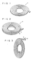
- This current-conductive air core coil represents either the single pancake coil 2 as shown in Fig. 1 or the double pancake coil 4 as shown in Fig. 2.
- the single pancake coil 2 is constructed by winding a hollow conductor in a spiral and double pancake-coil 4 is constructed by connecting pancake coils 6 and 8 at the inner ends thereof, said pancake 6 and 8 having been wound in opposite directions to form a spiral, respectively.
- the double pancake coil 4 may be constructed by winding a hollow conductor.
- One coil unit is formed by piling several or ten and several units of pancake coils one upon the other, and a plurality of these coil units is connected with one another to form a current-conductive air core coil.
- cooling liquid is flowed through each unit of the pancake coil.
- Diagnostic nuclear magnetic resonance devices and nuclear fusion research devices are demanded to use an equalized magnetic field.
- the strength of the magnetic field caused by the current-conductive air core coil is determined by the coil shape and the current flowing through the coil, while the uniformity thereof is determined by the coil shape. It is therefore necessary that the- shape dimension of the coil product is accurate in order to make uniform the magnetic field caused by the current-conductive air core coil.
- the conventional current-conductive coil is manufactured, as shown in Fig. 3, in such a manner that an insulating tape 12 is wound around a hollow conductor 10 in the process of winding the conductor 10, whose section is rectangular, in a spiral, and that the single or double pancake coil thus formed is fixed by fixing the conductor by prepreg.
- the troublesome process of winding the insulating tape 12 around the conductor 10 when the conductor is wound in a spiral is needed to insulate the conductor from its adjacent one. Therefore, the process of insulating the conductor from its adjacent one in the course of manufacturing the conventional current-conductive coil is a cause which makes it difficult to shorten its manufacturing time.
- a long air core coil conductor ranging from several hundred meters to several thousand meters is used particularly by diagnostic nuclear magnetic resonance devices and nuclear fusion research devices, and the insulating process for the conductor used, accordingly, takes an extremely long time to manufacture.
- the insulating tape 12 is wound around the conductor 10 in such a way that the insulating tape 12 is partly overlapped upon itself. Therefore, steps corresponding to the thickness of the overlapped insulating tape 12 are formed on the surface of the insulating tape wound around the conductor. The dimension accuracy of the single or double pancake coil thus wound is poor because of these steps, thus making it difficult to create a uniform magnetic field using the conventional current-conductive coil.
- a reliably sufficient insulation is achieved by winding the insulating tape 12 around the conductor 10.
- a high degree of insulation is achieved, though the current flowing through the conductor is small.
- the insulation process applied to the conventional conductor is more than enough in the case of diagnostic nuclear magnetic resonance devices.
- Prior art document AU-B-521 297 discloses a stack of pancake coils in which each pancake coil consists of a current conductor coil comprising a conductor wound in a spiral and having a pair of inner and outer fixing faces when viewed in the direction in which the conductor is wound in a spiral.
- a prepreg tape is interposed between the adjacent fixing faces of the conductor, said prepreg tape being wide enough to cover the fixing face, extending along the fixing face and being made of insulating material such as polyethylene teraphthalate or other suitable insulating material preimpregnated with thermosetting resin.
- Pads of glass fibre are provided between two adjacent pancake coils to form insulating means between these pancake coils.
- prior art document JP-A-5 752 107 describes a resin-immersed moulded coil which is produced by disposing a bare conductor and a hollow sleeve formed by weaving fibrous material in parallel-winding them and immersing it with resin.
- prior art document JP-A-53141401 shows straight line strip-like conductors between which there is provided some insulating material made of glass cloth or nylon fabric coated with thermosetting adhesive varnish.
- An object of the present invention is to provide a current-conductive coil and a method for manufacturing the current-conductive coil, which simplifies its electrically-insulating process in order to substantially shorten its manufacturing time, and enables its dimension accuracy to be made extremely high in order to create a highly- equalized magnetic field.
- a current-conductive coil comprising two pancake coils each including a rectangular conductor wound in a spiral and having a pair of inner and outer fixing faces when viewed in the direction in which the conductor is wound in a spiral, a prepreg tape extending along the fixing face and with a width enough to cover the fixing face, the prepreg tape being interposed between the adjacent fixing faces of the conductor to fix the fixing faces and electrically insulate the fixing faces from each other by being fused and solidified, and insulating means between the two pancake coils, said current-conductive coil being characterized in that said insulating means comprises a circular prepreg sheet sandwiched between the two pancake coils which are coaxially provided with their wound-directions opposed to each other, said pancake coils being fixed and electrically insulated from each other by fusing and solidifying of said prepreg sheet and the prepreg sheet consisting of a plurality of portions which are laid on the ring-shaped plain face of the pancake coils and arranged in the circumferential
- the current-conductive coil comprising: a first process of winding a rectangular conductor in a spiral and sandwiching a prepreg tape between the already-wound portion and to-be-wound portion of the conductor to form a single pancake coil, said prepreg tape having substantially the same width as that fixing face of the already-wound portion of the conductor where the to-be-wound portion of the conductor is wound, the method being characterized by further comprising a second process of coaxially putting two single pancake coils one upon the other with a circular prepreg sheet consisting of a plurality of portions which are laid on the ring-shaped plain face of the pancake coil and arranged in the circumferential direction of the pancake coil, and a third process of heating the prepreg tape and the prepreg sheet under a pressurized condition to fix the wound conductor and the single pancake coils to each other and to insulate the fixing face of the conductor from its adjacent one and one of the single pancake coil
- the double pancake coils can be manufactured by putting the two single pancake coils one upon the other with the prepreg sheet sandwiched between them, and heating the prepreg sheetto fix the single pancake coils with each other and to insulate them from each other.
- the double pancake coils can be thus manufactured more easily.
- the present invention enables the current-conductive coil to be manufactured with greater ease, at higher speed and with a lower cost in order that a uniform magnetic field may be created by the current-conductive coil.
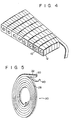
- a single pancake coil 20 shown in Fig. 5 includes a hollow conductor 22 wound in a spiral, and a prepreg tape 40 interposed along the conductor 22 when this is wound.
- the conductor 22 has a substantially rectangular section, and a hollow portion 24 in the center of its section extending along its longitudinal axis and through which cooling water flows.
- Four corners of the conductor 22 are chamfered to form chamfered portions 26.
- the prepreg tape 40 is prepared by cutting the prepreg in such a way that it is wide enough to cover the face of the conductor where the conductor is brought into contact with its adjacent inside one during the winding process.
- the prepreg itself is made by impregnating a sheet-shaped reinforcing material such as fabric, paper and mat with thermosetting resin.
- the thermosetting resin may be polyester, epoxydiaryl phthalate, phenol or solamine.
- the reinforcing material may be cloth of glass fabric, mat, rope, robe, paper, cotton fabric, nonwoven polyester fabric, or kraft paper. The glass cloth, for example, is immersed in epoxy resin liquid to impregnate both faces of the cloth with epoxy resin, thus making the prepreg.
- the prepreg is not sticky, and is easy to cut and treat.
- the resin impregnated in it becomes liquid to fill the space between the conductor and its adjacent inside one, and then hardens to fix the conductor.
- the hollow coil conductor 22 When the hollow coil conductor 22 is wound in a spiral, it is wound with the prepreg tape 40 interposed between its already-wound portion 28 and its to-be-wound portion 30, as shown in Fig. 5.
- the prepreg tape 40 is sandwiched between the outer circumferential face (fixing or overlapping face) of its inside portion and the inner circumferential face (fixing or overlapping face) of its outside portion to cover the whole of each of these faces, so that the single pancake coil 20 in which its inside portion (or already-wound portion) has been electrically insulated from its outside portion (or to-be-wound portion) can be obtained.
- Two single pancake coils 20 are then coaxially put one upon the other with prepreg sheets 42 sandwiched between them.
- the prepreg may be cut in a ring and then arranged on one of the pancake coils 20.
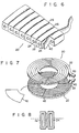
- the prepreg be cut into four prepreg sheets 42, for example, corresponding to the shape divided from the ring-shaped plain face of the pancake coil 20, and that these four prepreg sheets 42 are connected with one another in the circumferential direction of the pancake coil 20 and then arranged thereon.
- the dimension errors relating to the plain face of the pancake coil 20 and the shape of the prepreg sheets can be thus absorbed by the manner of arranging four prepreg sheets 42 on the plain face of the pancake coil 20.
- the plain face of the pancake coil 20 can be covered completely by the prepreg sheets 42 to thereby insulate one of the pancake coils 20 from the other electrically.
- These two pancake coils 20 are then fixed under a pressurized condition by means of a tool such as a metal frame.
- the pancake coils 20 thus pressurized and fixed are heated and dried in a heating furnace such as an electric furnace.
- the resins impregnated in the prepreg tape 40 and sheets 42 thus becomes liquid to fill the spaces between the inner and outer circumferential faces of the conductors 22 and also between the pancake coils 20.
- insulating layers of resin are formed between the circumferential faces of the conductors 22, and between the plain faces of the pancake coils 20 to fix the conductors 22.
- the resin becomes hardened by heating the prepreg at 130 to 150°C for 8 to 10 hours.
- the resin becomes hardened by heating the prepreg at 120°C for two hours.
- the conductor 22 has chamfer portions 26 formed at the four corners thereof, and these chamfer portions 26 serve as passages through which the heated resin moves and through which the excessive resin escapes, thus enabling the insulating layer of resin to be uniform. Even if any error is caused when the prepreg is cut to a tape 40 or even if any positional error is caused when the conductor 22 is wound, the conductor 22 is separated from its adjacent inside and outside ones at their chamfer portions, thus preventing any insulating trouble from happening.
- the thickness of the prepreg tape 40 or sheet 42 Is determined by voltages applied to the coil line and between the pancake coil lines. In the case of the hollow coil employed in the diagnostic nuclear magnetic resonance device, for example, it is enough to create a magnetic field of several kilo-gausses. Therefore, a voltage of only several tens volts is applied between the pancake coils. Since the insulating resistance of epoxy resin is larger than 10140 cm when expressed by the ratio of volume resistance, resistance larger than 30 MO can be obtained when the area of the resin layer is 10° n cm 2 and its thickness is 0.1 mm. Therefore, the prepreg layer, about 0.1 mm thick, is enough to serve as the insulator in the above application.
- the prepreg tape 40 or sheet 42 whose thickness is larger than 0.1 mm is usually employed, taking safety into consideration.
- resistance larger than 100 MQ can be obtained at a common temperature when the prepreg tape or sheet whose thickness is 0.32 mm is used.
- prepreg tapes or sheets of 0.3 mm thick are used in an overlapped manner rather than the prepreg tapes or sheets of 0.6 mm thick. This is because even if one of the prepreg tapes is slightly shifted from the circumferential face of the conductor 22, some portions of the circumferential face are left uncovered.
- the other tape can cover these uncovered portions to secure insulation between the circumferential face and its adjacent one. It is also preferable that the outermost circumferential face of the conductor is covered by a prepreg tape whose thickness is 0.5 mm so as to establish higher insulation, because the outermost circumferential face of the conductor is likely to be subjected to severe circumstances.
- the conductor is not wound by the insulating tape, but the prepreg tape 40 is overlapped onto the circumferential face of the conductor 22, thus enabling the insulating layer to be high in its dimension accuracy. Therefore, the dimension accuracy of the current-conductive coil is high.
- the diameter of the finished coil is different by only about 2 mm from the desired diameter even if the coil is a large-sized hollow coil for use in diagnostic nuclear magnetic resonance devices.
- the current-conductive coil according to the present invention is used, therefore, a uniform magnetic field can be created.
- the insulating process is easily done in the case of the method for manufacturing the current-conductive coil according to the present invention, thus allowing the current-conductive coil to be manufactured with more simplicity and at higher speed.
- Two pancake coils 20 are press-fixed with the prepreg sheets 42 interposed between them, and then heated to make the conductors adhere as in the above-described embodiment.
- each of the single pancake coils may be formed and then heated to make the conductors also adhere, and the two pancake coils 20 can be press-fixed with the prepreg sheets 42 sandwiched between them, and then heated to make these pancake coils 20 adhere to each other.
- the conductor is not limited to having a rectangular section; it may also be flat in section, as shown in Fig. 8. In short, it may have a linearly-extending portion at the edge of that area where its inner and outer sections 32 and 34 are opposed face to face. Further, its hollow portion 24 through which the cooling water flows is not limited to having a circular section; it may also be rectangular in section, as shown in Fig. 8.
- the pancake coils press-fixed by metal frame have been heated in a heating furnace in the above-described embodiment.
- the resins may be heated by that resistance heat of the conductors themselves which is caused by applying current to the conductors in the pancake coils which have been press-fixed by a metal frame.
Landscapes
- Engineering & Computer Science (AREA)
- Power Engineering (AREA)
- Manufacturing & Machinery (AREA)
- Insulating Of Coils (AREA)
Claims (8)
Applications Claiming Priority (2)
| Application Number | Priority Date | Filing Date | Title |
|---|---|---|---|
| JP20588/83 | 1983-02-10 | ||
| JP2058883A JPS59150405A (ja) | 1983-02-10 | 1983-02-10 | 常電導コイルおよびその製造方法 |
Publications (2)
| Publication Number | Publication Date |
|---|---|
| EP0116367A1 EP0116367A1 (fr) | 1984-08-22 |
| EP0116367B1 true EP0116367B1 (fr) | 1987-08-26 |
Family
ID=12031390
Family Applications (1)
| Application Number | Title | Priority Date | Filing Date |
|---|---|---|---|
| EP19840101233 Expired EP0116367B1 (fr) | 1983-02-10 | 1984-02-07 | Enroulement conducteur de courant et procédé de fabrication de celui-ci |
Country Status (3)
| Country | Link |
|---|---|
| EP (1) | EP0116367B1 (fr) |
| JP (1) | JPS59150405A (fr) |
| DE (1) | DE3465663D1 (fr) |
Cited By (1)
| Publication number | Priority date | Publication date | Assignee | Title |
|---|---|---|---|---|
| DE4438187A1 (de) * | 1994-10-26 | 1996-05-02 | Abb Management Ag | Elektrischer Leiter für Wicklungen mit verteiltem Überspannungsschutz |
Families Citing this family (12)
| Publication number | Priority date | Publication date | Assignee | Title |
|---|---|---|---|---|
| DE3613682A1 (de) * | 1986-04-23 | 1987-10-29 | Bruker Analytische Messtechnik | Verfahren und vorrichtung zum kuehlen eines resistiven magnetsystems fuer kernspintomographen |
| JP3504352B2 (ja) * | 1994-10-05 | 2004-03-08 | 三菱電機株式会社 | 車両用交流発電機の回転子 |
| GB0329387D0 (en) | 2003-12-18 | 2004-01-21 | Rolls Royce Plc | Coils for electrical machines |
| JP4752744B2 (ja) * | 2006-11-30 | 2011-08-17 | 住友電気工業株式会社 | 超電導コイル |
| JP5269556B2 (ja) * | 2008-11-18 | 2013-08-21 | 株式会社東芝 | 超電導コイルの製造方法、及び超電導コイルの製造装置 |
| EP2390885B1 (fr) * | 2010-05-26 | 2013-01-09 | ABB Technology AG | Procédé de fabrication d'enroulements pour un transformateur sec |
| DE102011078590B4 (de) * | 2011-07-04 | 2013-03-07 | Siemens Aktiengesellschaft | Supraleitende Spulenanordnung und Verfahren zu deren Herstellung |
| ITAQ20120007A1 (it) * | 2012-12-12 | 2014-06-13 | Antonello Sotgiu | Magnete solenoidale con dischi a spirale per la generazione di campi impulsati caratterizzati da alta omogeneita' e alta intensita' di campo magnetico per applicazioni in imaging tramite risonanze magnetiche. |
| JP2015046518A (ja) * | 2013-08-29 | 2015-03-12 | 住友電気工業株式会社 | 超電導コイルおよび超電導コイルの製造方法 |
| CN204117812U (zh) * | 2014-07-25 | 2015-01-21 | 海鸿电气有限公司 | 一种敞开式立体卷铁心干式变压器的线圈结构 |
| CN104103388A (zh) * | 2014-07-25 | 2014-10-15 | 广东海鸿变压器有限公司 | 一种绝缘纸的浸漆工艺 |
| CN110350321B (zh) * | 2018-04-02 | 2024-04-12 | 法雷奥舒适驾驶助手公司 | 用于无线电力传输的天线及其制造方法 |
Family Cites Families (9)
| Publication number | Priority date | Publication date | Assignee | Title |
|---|---|---|---|---|
| US1389149A (en) * | 1917-09-01 | 1921-08-30 | Westinghouse Electric & Mfg Co | Insulating-coil and method of making same |
| GB715226A (en) * | 1952-04-07 | 1954-09-08 | Dowty Equipment Ltd | Improvements relating to electro-magnetic coils |
| US3068433A (en) * | 1954-04-15 | 1962-12-11 | Sylvania Electric Prod | Electromagnetic coils |
| DE1049007B (de) * | 1954-11-16 | 1959-01-22 | Oerlikon Maschf | Magnetwicklung |
| US3868766A (en) * | 1973-08-31 | 1975-03-04 | Ford Motor Co | Method of forming an insulated coil for a dynamoelectric machine |
| JPS5185693A (ja) * | 1975-01-24 | 1976-07-27 | Mitsubishi Atomic Power Ind | Entogatachodendokoirusochi |
| JPS5457161A (en) * | 1977-10-14 | 1979-05-08 | Hitachi Ltd | Preparation of doughnuttlike coil |
| AU521297B2 (en) * | 1978-11-01 | 1982-03-25 | English Electric Co. Ltd., The | Encapsulated high voltage windings |
| EP0030338B1 (fr) * | 1979-12-11 | 1985-04-03 | Asea Ab | Conducteur électrique isolé pour enroulements de transformateurs et de bobines de self |
-
1983
- 1983-02-10 JP JP2058883A patent/JPS59150405A/ja active Pending
-
1984
- 1984-02-07 DE DE8484101233T patent/DE3465663D1/de not_active Expired
- 1984-02-07 EP EP19840101233 patent/EP0116367B1/fr not_active Expired
Cited By (1)
| Publication number | Priority date | Publication date | Assignee | Title |
|---|---|---|---|---|
| DE4438187A1 (de) * | 1994-10-26 | 1996-05-02 | Abb Management Ag | Elektrischer Leiter für Wicklungen mit verteiltem Überspannungsschutz |
Also Published As
| Publication number | Publication date |
|---|---|
| EP0116367A1 (fr) | 1984-08-22 |
| DE3465663D1 (en) | 1987-10-01 |
| JPS59150405A (ja) | 1984-08-28 |
Similar Documents
| Publication | Publication Date | Title |
|---|---|---|
| EP0116367B1 (fr) | Enroulement conducteur de courant et procédé de fabrication de celui-ci | |
| US4173747A (en) | Insulation structures for electrical inductive apparatus | |
| US4552990A (en) | Insulated conductor for transformer windings and other inductive apparatus | |
| JPH0447964B2 (fr) | ||
| EP0672521B1 (fr) | Isolateur en feuille composite mince, son procédé de fabrication et machine électrique rotative le contenant | |
| JP2007282410A (ja) | 回転電機の固定子コイル、回転電機の固定子コイルの製造方法、半導電性シート、半導電性テープ、および回転電機 | |
| KR900000433B1 (ko) | 전자교반 장치용 수냉권선 | |
| US3657808A (en) | Methods of constructing electrical coils | |
| JP7196362B2 (ja) | 電磁誘導装置の電気巻線を製造するための方法および導体構造 | |
| JP3651629B2 (ja) | 高圧回転機固定子絶縁コイル | |
| JP2979887B2 (ja) | 電気機器コイル及びコイルを有する電気機器並びにその製造方法 | |
| JPH02240901A (ja) | 電気機器のコイル絶縁 | |
| JP2817044B2 (ja) | モールドコイル | |
| JPS62124707A (ja) | 電磁撹拌装置用水冷巻線 | |
| JPH0464443B2 (fr) | ||
| JPS605206B2 (ja) | 電気機器コイルおよびその製造方法 | |
| JPH09330826A (ja) | 変圧器巻線 | |
| US20240131820A1 (en) | Resin film | |
| JPH0447938Y2 (fr) | ||
| JPS6199311A (ja) | 樹脂モールドコイル | |
| JPH0349366Y2 (fr) | ||
| JPH0719692B2 (ja) | 超電導コイル | |
| JPS60127705A (ja) | 常電導コイルの製造方法 | |
| JPH0342689B2 (fr) | ||
| JPH05144654A (ja) | 電磁石用コイルの製造方法 |
Legal Events
| Date | Code | Title | Description |
|---|---|---|---|
| PUAI | Public reference made under article 153(3) epc to a published international application that has entered the european phase |
Free format text: ORIGINAL CODE: 0009012 |
|
| 17P | Request for examination filed |
Effective date: 19840302 |
|
| AK | Designated contracting states |
Designated state(s): DE FR GB NL |
|
| RAP1 | Party data changed (applicant data changed or rights of an application transferred) |
Owner name: KABUSHIKI KAISHA TOSHIBA |
|
| GRAA | (expected) grant |
Free format text: ORIGINAL CODE: 0009210 |
|
| AK | Designated contracting states |
Kind code of ref document: B1 Designated state(s): DE FR GB NL |
|
| ET | Fr: translation filed | ||
| REF | Corresponds to: |
Ref document number: 3465663 Country of ref document: DE Date of ref document: 19871001 |
|
| PLBE | No opposition filed within time limit |
Free format text: ORIGINAL CODE: 0009261 |
|
| STAA | Information on the status of an ep patent application or granted ep patent |
Free format text: STATUS: NO OPPOSITION FILED WITHIN TIME LIMIT |
|
| 26N | No opposition filed | ||
| PG25 | Lapsed in a contracting state [announced via postgrant information from national office to epo] |
Ref country code: GB Effective date: 19890207 |
|
| PG25 | Lapsed in a contracting state [announced via postgrant information from national office to epo] |
Ref country code: NL Effective date: 19890901 |
|
| NLV4 | Nl: lapsed or anulled due to non-payment of the annual fee | ||
| GBPC | Gb: european patent ceased through non-payment of renewal fee | ||
| PG25 | Lapsed in a contracting state [announced via postgrant information from national office to epo] |
Ref country code: FR Free format text: LAPSE BECAUSE OF NON-PAYMENT OF DUE FEES Effective date: 19891027 |
|
| PG25 | Lapsed in a contracting state [announced via postgrant information from national office to epo] |
Ref country code: DE Effective date: 19891101 |
|
| REG | Reference to a national code |
Ref country code: FR Ref legal event code: ST |