EP0116017A1 - Electric household appliance for cutting fruit, vegetables and similar food products into small sticks or chunks of variable thickness - Google Patents
Electric household appliance for cutting fruit, vegetables and similar food products into small sticks or chunks of variable thickness Download PDFInfo
- Publication number
- EP0116017A1 EP0116017A1 EP84830001A EP84830001A EP0116017A1 EP 0116017 A1 EP0116017 A1 EP 0116017A1 EP 84830001 A EP84830001 A EP 84830001A EP 84830001 A EP84830001 A EP 84830001A EP 0116017 A1 EP0116017 A1 EP 0116017A1
- Authority
- EP
- European Patent Office
- Prior art keywords
- disc
- shaft
- cutting tool
- duct
- hopper
- Prior art date
- Legal status (The legal status is an assumption and is not a legal conclusion. Google has not performed a legal analysis and makes no representation as to the accuracy of the status listed.)
- Granted
Links
- 235000013305 food Nutrition 0.000 title claims abstract description 17
- 235000013399 edible fruits Nutrition 0.000 title claims abstract description 7
- 235000013311 vegetables Nutrition 0.000 title claims abstract description 7
- 230000008878 coupling Effects 0.000 abstract description 9
- 238000010168 coupling process Methods 0.000 abstract description 9
- 238000005859 coupling reaction Methods 0.000 abstract description 9
- 239000000463 material Substances 0.000 description 2
- 239000002184 metal Substances 0.000 description 2
- 229920003023 plastic Polymers 0.000 description 2
- 239000004033 plastic Substances 0.000 description 2
- 230000015572 biosynthetic process Effects 0.000 description 1
- 230000000694 effects Effects 0.000 description 1
- 238000004519 manufacturing process Methods 0.000 description 1
- 238000002156 mixing Methods 0.000 description 1
- 239000002699 waste material Substances 0.000 description 1
- 238000003466 welding Methods 0.000 description 1
Images

Classifications
-
- B—PERFORMING OPERATIONS; TRANSPORTING
- B26—HAND CUTTING TOOLS; CUTTING; SEVERING
- B26D—CUTTING; DETAILS COMMON TO MACHINES FOR PERFORATING, PUNCHING, CUTTING-OUT, STAMPING-OUT OR SEVERING
- B26D3/00—Cutting work characterised by the nature of the cut made; Apparatus therefor
- B26D3/18—Cutting work characterised by the nature of the cut made; Apparatus therefor to obtain cubes or the like
- B26D3/22—Cutting work characterised by the nature of the cut made; Apparatus therefor to obtain cubes or the like using rotating knives
- B26D3/225—Cutting work characterised by the nature of the cut made; Apparatus therefor to obtain cubes or the like using rotating knives with adjustable knives
-
- B—PERFORMING OPERATIONS; TRANSPORTING
- B26—HAND CUTTING TOOLS; CUTTING; SEVERING
- B26D—CUTTING; DETAILS COMMON TO MACHINES FOR PERFORATING, PUNCHING, CUTTING-OUT, STAMPING-OUT OR SEVERING
- B26D3/00—Cutting work characterised by the nature of the cut made; Apparatus therefor
- B26D3/24—Cutting work characterised by the nature of the cut made; Apparatus therefor to obtain segments other than slices, e.g. cutting pies
- B26D3/26—Cutting work characterised by the nature of the cut made; Apparatus therefor to obtain segments other than slices, e.g. cutting pies specially adapted for cutting fruit or vegetables, e.g. for onions
Definitions
- the present invention relates to electric household appliances for cutting fruit, vegetables and similar food products into small sticks or chunks of variable- thickness, comprising essentially a container, a motor-driven shaft extendino longitudinally and axially in the container, a disc mounted on the motor-driven shaft with which it is fixed for rotation, a hopper-duct extending parallel to and eccentrically of the motor-driven shaft and having one end opening into the container for the introduction against the disc of food products to be cut, the disc defining an aperture for the passage of the cut products into the bottom of the container.
- the invention concerns an electric .household appliance of the so-called multi-function type in that it can use different implements, tools or devices for performing corresponding functions such as, for example, mincing, slicing, cutting, squeezing, centrifuging, blending and the like.
- a tool which, in most cases, comprises a plurality of blades fixed to the disc (or formed directly on the disc) and projecting from one face thereof, the blades being aligned radially on this face.
- Each blade has an essentially right-angled shape, with a portion perpendicular to the disc and a portion substantially parallel thereto. The blade portions perpendicular to the disc cut the product into strips, while the blade portions parallel to the disc further cut the strips as they are produced.
- the portion perpendicular to the .disc must have an "earlier" impact on the product to be cut than that of the portion (of the blade) parallel to the disc.
- the transverse dimensions of the small sticks or chunks of product obtained are determined by the length of the blade portions perpendicular to the disc and by their mutual spacing in their radial alignment on the disc.
- the cutting tools of this type In order to overcome the technical and economical disadvantages presented by the cutting tools of this type, it has been proposed to provide a plurality of open seats on one face of a disc, and to locate an essentially comb-shaped tool in each seat in a "disappearing"manner. More particularly, the respective cutting tool is angularly displaceable in each seat about a pin on which it is rotatably mounted between an operative position in which the blades project perpendicular to the disc, and an inoperative position in which the blades are withdrawn into the seat and in which a flat back of the tool reconstitutes the continuity of the surface of the disc considered.
- the dimensioning of the small sticks or chunks of product is entrusted solely to the distance between the blades of each tool.
- the technical problem which it is intended to solve by this invention is that of providing an electric household appliance of the type under consideration, having structural and functional characteristics such as to overcome the disadvatnages cited above with reference to the prior art.
- an electric household appliance according to the invention which is characterised in that it comprises:
- the electric appliance of the invention is further characterised in that it includes a slicing blade which projects laterally and radially with respect to a hub and is fixed coaxially for rotation with the mootr-driven shaft, the slicing blade being substantially coplanar with the end of the hopper-duct and rotating edgewise thereto.
- the disc with the slots through which the blades of the cutting tool pass is adjustably positioned between the cutting tool and the slicing blade.
- an electric appliance includes a single disc and a single cutting tool for producing small sticks or chunks of any suitable food product, of any desired thickness, by simply varying the position of the disc on the motor-driven shaft. Consequently, since fewer accessories are necessary than in the prior art, clear advantages of economy of production and economy of space are achieved, together with facility of handling upon assembly and removal of the accessories.
- a further important advantage achieved by the invention is constituted by the fact that the cutting tool has a precise position on the motor-driven shaft, a position which need not be varied when it is desired to vary the thickness of the small sticks or chunks produced.
- the advantages are increased when the electric household appliance in question is of the multi-functional type. Indeed, it should be borne in mind that the slicing blade and the disc with the plurality of slots may be used for the widely required function of slicing fruit, vegetables and similar food products with the possibility of varying the thickness of the slices at will.
- an electric household appliance comprises a box-like body 1 with one part 2 which is intended to receive a drive unit and its accessories, not shown since they are entirely conventional, and is alongside an essentially basal or support part 3.
- a substantially cylindrical projection 5 In the centre of the upper wall 4 of the base 3 is a substantially cylindrical projection 5 having an axial through-hole 6.
- a motor-driven shaft 7 is rotatably supported in the hole 6 with the interposition of bearings, schematically indicated 8.
- a container 9 is intended to rest on the base 3 and has a bottom 10 provided centrally with a tubular part 11 which extends axially inwardly of the container itself.
- the tubular portion 11 coaxially surrounds the motor-driven shaft 7 which thus extends axially within the container,
- the container 9 can be closed by means of a lid 12 formed with a duct 13 which, when the lid is fitted on the container 9, extends eccentrically relative to the motor-driven shaft 7 and has an end 14 which opens into the container 9.
- the duct 13 is used for, passing fruit, vegetables or similar food products which are to be cut into small sticks or chunks into the container 9. For this reason, the duct 13 will be called the hopper-duct in the following description and in the subsequent claims.
- a shaft 15 having an axial through-hole is fitted axially onto the portion of the motor-driven shaft 7 which projects from the base 3, and is fixed for rotation with the motor-driven shaft, for example, by means of a splined coupling 16 or other similar coupling.
- the shaft 15 has an upper portion 17 extending into the container 9 above the tubular portion 11 thereof.
- a cutting tool used in the electric household appliance of the invention is generally indicated 18 (Figure 7).
- This cutting tool 18 comprises a plurality of blaes, each indicated 19,fixed essentially like a comb onto an arm 20.
- the arm 20 is fixed so that it projects laterally from,or is formed in one piece with, a hollow hub 21 from which the arm 20 extends radially.
- On the inner wall of the hub 21 is formed or otherwise fixed a radial pin 22 by means of which the hub may be fixed coaxially and releasably by bayonet engagement to the upper portion17 of the shaft 15, with which it is thus locked for rotation.
- the coupling between the hub 21 and the shaft 15 may be achieved by other means entirely equivalent to bayonet engagement, which are well known in this branch of the art.
- the arm 20 is spaced from the end 14 of the hopper-duct 13 which opens into the container 9 by a distance equal to the length of the blades 19. Consequently, the upper ends of the blades are very close to the open end 14 of the hopper-duct 13.
- the blades 19 mentioned above are constituted by the limbs of U-shaped elements 23 ( Figure 7) which are sharpened on one edge and fixed, for example by welding, to a metal insert 24 formed wiLh a right angle and embedded in the plastics material which preferably constitutes the arm 20 and its hub 21.
- a disc 25 ( Figures 4 and 5), also preferably of synthetic, atoxic plastics material, is provided at its centre with a tubular hub 26 by means of which the disc.25 is fixed coaxially for rotation to the portion .17 of the shaft 15 in a position between the cutting tool 18 and the open end 14 of the hopper-duct 13.
- the disc 25 can also be adjusted in its position along the axis of rotation of the shaft 15.
- the hub 26 of the disc 25 is mounted on the portion 17 of the shaft 15 by means of a splined coupling, schematically indicated 27.
- the hub 26 of the disc 25 is engaged in a cylindrical cavity 28 formed coaxially in the upper end of the portion 17 of the shaft 15, the splined coupling being formed in the cavity.
- the disc 25 is also formed with radially aligned slots 29 dimensioned so as to allow the free passage of the blades 19 of the cutting tool 18.
- the disc 25 also defines, in an appropriate position, a large shaped aperture 30 for allowing the product cut into small sticks or chunks to pass into the bottom 10 of the container 9. ( Figure 6)
- a slicing blade 31 has an annular portion 32 constituting essentially a flattened hub by means of which the blade is fixed for rotation with the motor-driven shaft 7.
- four columns 34 ( Figures 2 and 3) are formed or otherwise fixed to the portion 17 of the hollow shaft 15 in positions diametrally opposite each other so that they extend parallel to the axis of the portion 17 and project beyond the cylindrical cavity 28 formed therein. It should be noted that the small columns 34 also pass beyond the disc 25 through four corresponding apertures 35 formed therein ( Figure 4).
- the flattened hub 32 of the slicing blade 31 is fixed to the upper ends of the columns 34, for example, by means of screws schematically indicated 33 . ( Figure 6)
- the slicing blade 31 extends so as to be coplanar with the open end 14 of the hopper-duct 13 and rotates edgewise thereto.
- the angular position of the slicing blade 31 and the cutting tool 18 relative to the axis of rotation of the motor-driven shaft 7 is chosen so that the blades 19 of the cutting toolhave an earlier impact on the product to be cut than the slicing blade 31.
- a knob 36 rests so as to be freely rotatable on the flattened hub 32,and the upper portion 37 of a shaft, generally indicated 38 ; extending coaxially with the motor driven shaft 7 is fixed axially to the knob 36.
- the shaft 38 has a lower threaded portion 39 screwed into a threaded hole 40 formed axially in a metal insert 41 embedded coaxially in the hub 26 of the disc 25.
- Rotation of the knob 36 causes the screwing or unscrewing of the threaded portion 39 of the shaft 38 relative to the threaded hole 40 and hence causes a movement of the disc 25 along the axis of the motor-driven shaft 7. Consequently,the disc may be located at any position between the cutting device 18 and the slicing blade 31.
- Figure 9 shows a variant of the cutting tool,now generally indicated 42.
- the tool comprises an arm 44 fixed laterally to or formed in one piece with a hollow hub 45,and a plurality of blades 43 fixed to the arm 44 and extending parallel to the axis of the hollow hub 45.
- the blades 43 are located along a curved line with a profile substantially the same as the cutting profile of the slicing blade 31,for example, a profile substantially in the form of a portion of a spiral with the convex side facing in the direction of rotation.
- the blades 43 come into contact with the product to be cut one after the other and avoid exerting a tearing effect on the product, which could occur if all the blades of a cutting tool contact the product simultaneously.
- the disc 25 ( Figure 8) will have a line of slots 46 corresponding to the blades 43 of the cutting tool 42.
- the main advantage of this invention is that of enabling the thickness of the small sticks or chunks of food product cut by the electric appliance described above to be varied at will. Indeed, by operating the knob 36, one can vary the position of the disc 25 relative to the open end 14 of the hopper-duct 13 and vary the thickness of food product which projects from the hopper into the container 9 and rests ' or bears on the disc 25. It should be noted that the adjustment of the position of the disc 25 occurs without any adjustment of the portion of the cutting tool 18 which remains locked in its initial predetermined position on the hollow shaft 15; this is contrary to what is required in the electric household appliances of the prior art. This is a further important advantage achieved by the present invention.
- the slicing blade 31 and the disc 25 constitute the tools for the function of slicing food products with the possibility of varying the thickness of the slices obtained. Consequently, in such a multi-function electric appliance it is possible, with only three accessories(the cutting tool 18, the disc 25 and the slicing blade 31) to carry out two basic functions: that of slicing and that of cutting into small sticks or chunks of variable thicknesses.
- a further, not inconsiderable advantage is constituted by the fact that the aforementioned adjustable positioning of the disc 25 can be achieved by operating a knob which is readily accessible upon the simple removal of the lid 12.
Landscapes
- Life Sciences & Earth Sciences (AREA)
- Forests & Forestry (AREA)
- Engineering & Computer Science (AREA)
- Mechanical Engineering (AREA)
- Food-Manufacturing Devices (AREA)
- Crushing And Pulverization Processes (AREA)
Abstract
Description
- The present invention relates to electric household appliances for cutting fruit, vegetables and similar food products into small sticks or chunks of variable- thickness, comprising essentially a container, a motor-driven shaft extendino longitudinally and axially in the container, a disc mounted on the motor-driven shaft with which it is fixed for rotation, a hopper-duct extending parallel to and eccentrically of the motor-driven shaft and having one end opening into the container for the introduction against the disc of food products to be cut, the disc defining an aperture for the passage of the cut products into the bottom of the container.
- More particularly, the invention concerns an electric .household appliance of the so-called multi-function type in that it can use different implements, tools or devices for performing corresponding functions such as, for example, mincing, slicing, cutting, squeezing, centrifuging, blending and the like.
- With regard to electric appliances of this type, it is known that the present trend is to qive them the greatest number of possible functions, widening the range of accessory tools. It is also known that one of the functions required most particularly from such electric appliances is that of cutting fruit, vegetables and similar food products into small sticks or chunks.
- For such a function, it is necessary for the portion of food product to be cut between the disc and the end of the hopper-duct which opens into the container to be cut firstly into strips substantially perpendicular to the disc and then for these strips to be cut again in line with the end of the hopper-duct.
- For this purpose, general use is made of a tool which, in most cases, comprises a plurality of blades fixed to the disc (or formed directly on the disc) and projecting from one face thereof, the blades being aligned radially on this face. Each blade has an essentially right-angled shape, with a portion perpendicular to the disc and a portion substantially parallel thereto. The blade portions perpendicular to the disc cut the product into strips, while the blade portions parallel to the disc further cut the strips as they are produced.
- Thus, with each blade, the portion perpendicular to the .disc must have an "earlier" impact on the product to be cut than that of the portion (of the blade) parallel to the disc.
- Moreover, the transverse dimensions of the small sticks or chunks of product obtained are determined by the length of the blade portions perpendicular to the disc and by their mutual spacing in their radial alignment on the disc.
- Consequently in order to produce small sticks or chunks of different types with different transverse dimensions,it is necessary to vary the length and/or the distance between the blade portions perpendicular to the disc. Thus it is necessary to provide as many tools (discs plus cutting blades) as the number of types of small sticks or chunks of product which are likely to be made. Moreover, it is necessary for each tool (particularly the disc part thereof) and the motor-driven shaft of the appliance to be formed such as to allow the disc to be positioned at a suitable distance from the end of the hopper-duct which opens into the container of the appliance in question.
- In order to overcome the technical and economical disadvantages presented by the cutting tools of this type, it has been proposed to provide a plurality of open seats on one face of a disc, and to locate an essentially comb-shaped tool in each seat in a "disappearing"manner. More particularly, the respective cutting tool is angularly displaceable in each seat about a pin on which it is rotatably mounted between an operative position in which the blades project perpendicular to the disc, and an inoperative position in which the blades are withdrawn into the seat and in which a flat back of the tool reconstitutes the continuity of the surface of the disc considered.
- According to this proposal, the dimensioning of the small sticks or chunks of product is entrusted solely to the distance between the blades of each tool.
- In addition to the obvious, not inconsiderable difficulty of providing a disc with several cutting tools, and the costs involved in this provision, there is also a disadvantage of a strictly technical nature which rapidly renders the disc unusable.
- Indeed, the very frequent knocks to which the blades of each tool are subject during cutting of a food product lead to corresponding fatigue of some importance in the supports for the pin, and in the pin on which the tool is mounted itself. Consequently, more or less considerable deformation of the pin may occur together with more or less rapid formation of play in the pin-support couplings, which may cause malfunctioning of the cutting tool or the actual detachment thereof from the support disc.
- Another, not inconsiderable disadvantage is that waste collects easily in the seats formed in the disc for the "disappearing" support of the tools, the removal of which is essential and requires attention and time.
- In view of the above, the technical problem which it is intended to solve by this invention is that of providing an electric household appliance of the type under consideration, having structural and functional characteristics such as to overcome the disadvatnages cited above with reference to the prior art.
- This problem is resolved by an electric household appliance according to the invention, which is characterised in that it comprises:
- - a cutting tool which is structurally independent of the disc and includes a plurality of blades fixed in a comb-like manner to an arm fixed releasably for rotation with the motor-driven shaft relative to which the arm extends radially at a distance from that end of the hopper-duct opening into the container, which is substantially equal to the length of the blades,
- - a plurality of slots defined by the disc, each of which is passed through by a corresponding blade of the cutting tool, the disc being axially movably coupled to the motor-driven shaft, and
- - means for adjusting the position of the disc along the axis of the motor-driven shaft.
- The electric appliance of the invention is further characterised in that it includes a slicing blade which projects laterally and radially with respect to a hub and is fixed coaxially for rotation with the mootr-driven shaft, the slicing blade being substantially coplanar with the end of the hopper-duct and rotating edgewise thereto.
- According to a third characteristic of the invention, the disc with the slots through which the blades of the cutting tool pass is adjustably positioned between the cutting tool and the slicing blade.
- The principle and more immediate advantage achieved by an electric appliance according to the invention is constituted by the fact that it includes a single disc and a single cutting tool for producing small sticks or chunks of any suitable food product, of any desired thickness, by simply varying the position of the disc on the motor-driven shaft. Consequently, since fewer accessories are necessary than in the prior art, clear advantages of economy of production and economy of space are achieved, together with facility of handling upon assembly and removal of the accessories.
- A further important advantage achieved by the invention is constituted by the fact that the cutting tool has a precise position on the motor-driven shaft, a position which need not be varied when it is desired to vary the thickness of the small sticks or chunks produced.
- The advantages are increased when the electric household appliance in question is of the multi-functional type. Indeed, it should be borne in mind that the slicing blade and the disc with the plurality of slots may be used for the widely required function of slicing fruit, vegetables and similar food products with the possibility of varying the thickness of the slices at will.
- Further characteristics and advantages will become clearer from the description of one embodiment of an electric household appliance according to the invention given below, by way of non-limiting example, with reference to the appended drawings, in which:
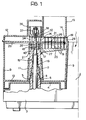
- Figure 1 shows, in section, an electric appliance according to the invention;
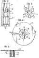
- Figure 2 is a longitudinal section showing a detail of the electric appliance of,Figure 1 on an enlarged scale;
- Figure 3 is a plan view of the detail of Figure 2;
- Figure 4 is a plan view of a further detail of the machine of Figure 1;
- Figure 5 is a section taken on the line V-V of Figure 4;
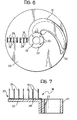
- Figure 6 is a schematic plan view of the basic components of the appliance of Figure 1 for cutting food products of the type considered into small sticks or chunks;
- Figure 7 is a sectional view, on an enlarged scale, of a cutting tool used in the electric appliance of Figure 1;
- Figure 8 is a variant of the components of Figure 6, and
- Figure 9 is a schematic side view of a cutting tool according to a variant.
- With reference to the drawings, an electric household appliance according to the invention comprises a box-like body 1 with one part 2 which is intended to receive a drive unit and its accessories, not shown since they are entirely conventional, and is alongside an essentially basal or support part 3. In the centre of the upper wall 4 of the base 3 is a substantially
cylindrical projection 5 having an axial through-hole 6. A motor-driven shaft 7 is rotatably supported in thehole 6 with the interposition of bearings, schematically indicated 8. - A container 9 is intended to rest on the base 3 and has a
bottom 10 provided centrally with atubular part 11 which extends axially inwardly of the container itself. When the container 9 is located and locked on the base 3 by conventional means, not shown, thetubular portion 11 coaxially surrounds the motor-driven shaft 7 which thus extends axially within the container, - The container 9 can be closed by means of a
lid 12 formed with aduct 13 which, when the lid is fitted on the container 9, extends eccentrically relative to the motor-driven shaft 7 and has anend 14 which opens into the container 9. Theduct 13 is used for, passing fruit, vegetables or similar food products which are to be cut into small sticks or chunks into the container 9. For this reason, theduct 13 will be called the hopper-duct in the following description and in the subsequent claims. - A
shaft 15 having an axial through-hole is fitted axially onto the portion of the motor-driven shaft 7 which projects from the base 3, and is fixed for rotation with the motor-driven shaft, for example, by means of asplined coupling 16 or other similar coupling. Theshaft 15 has anupper portion 17 extending into the container 9 above thetubular portion 11 thereof. - A cutting tool used in the electric household appliance of the invention is generally indicated 18 (Figure 7). This
cutting tool 18 comprises a plurality of blaes, each indicated 19,fixed essentially like a comb onto anarm 20. In its turn, thearm 20. is fixed so that it projects laterally from,or is formed in one piece with, ahollow hub 21 from which thearm 20 extends radially. On the inner wall of thehub 21 is formed or otherwise fixed aradial pin 22 by means of which the hub may be fixed coaxially and releasably by bayonet engagement to the upper portion17 of theshaft 15, with which it is thus locked for rotation. - Clearly, the coupling between the
hub 21 and the shaft 15 (that is to say, the coupling between the cutting tool 1:8 and the motor-driven shaft 7) may be achieved by other means entirely equivalent to bayonet engagement, which are well known in this branch of the art. - It should be noted that, with this coupling, the
arm 20 is spaced from theend 14 of the hopper-duct 13 which opens into the container 9 by a distance equal to the length of theblades 19. Consequently, the upper ends of the blades are very close to theopen end 14 of the hopper-duct 13. - In accordance with one preferred but non-limiting embodiment, the
blades 19 mentioned above are constituted by the limbs of U-shaped elements 23 (Figure 7) which are sharpened on one edge and fixed, for example by welding, to ametal insert 24 formed wiLh a right angle and embedded in the plastics material which preferably constitutes thearm 20 and itshub 21. - A disc 25 (Figures 4 and 5),also preferably of synthetic, atoxic plastics material, is provided at its centre with a
tubular hub 26 by means of which the disc.25 is fixed coaxially for rotation to the portion .17 of theshaft 15 in a position between thecutting tool 18 and theopen end 14 of the hopper-duct 13. Thedisc 25 can also be adjusted in its position along the axis of rotation of theshaft 15. For this purpose, thehub 26 of thedisc 25 is mounted on theportion 17 of theshaft 15 by means of a splined coupling, schematically indicated 27. In accordance with a preferred embodiment which is clearly not limiting, thehub 26 of thedisc 25 is engaged in acylindrical cavity 28 formed coaxially in the upper end of theportion 17 of theshaft 15, the splined coupling being formed in the cavity. - The
disc 25 is also formed with radially alignedslots 29 dimensioned so as to allow the free passage of theblades 19 of thecutting tool 18. (Figure - The
disc 25 also defines, in an appropriate position,a large shapedaperture 30 for allowing the product cut into small sticks or chunks to pass into the bottom 10 of the container 9. (Figure 6) - A
slicing blade 31 has anannular portion 32 constituting essentially a flattened hub by means of which the blade is fixed for rotation with the motor-driven shaft 7. For this purpose, in accordance with one preferred embodiment, four columns 34 (Figures 2 and 3) are formed or otherwise fixed to theportion 17 of thehollow shaft 15 in positions diametrally opposite each other so that they extend parallel to the axis of theportion 17 and project beyond thecylindrical cavity 28 formed therein. It should be noted that thesmall columns 34 also pass beyond thedisc 25 through fourcorresponding apertures 35 formed therein (Figure 4). The flattenedhub 32 of theslicing blade 31 is fixed to the upper ends of thecolumns 34, for example, by means of screws schematically indicated 33. (Figure 6) - The
slicing blade 31 extends so as to be coplanar with theopen end 14 of the hopper-duct 13 and rotates edgewise thereto. - It should be noted in particular that the angular position of the
slicing blade 31 and thecutting tool 18 relative to the axis of rotation of the motor-driven shaft 7 is chosen so that theblades 19 of the cutting toolhave an earlier impact on the product to be cut than theslicing blade 31. - A
knob 36 rests so as to be freely rotatable on the flattenedhub 32,and theupper portion 37 of a shaft, generally indicated 38 ; extending coaxially with the motor driven shaft 7 is fixed axially to theknob 36. Theshaft 38 has a lower threadedportion 39 screwed into a threadedhole 40 formed axially in ametal insert 41 embedded coaxially in thehub 26 of thedisc 25. - Rotation of the
knob 36 causes the screwing or unscrewing of the threadedportion 39 of theshaft 38 relative to the threadedhole 40 and hence causes a movement of thedisc 25 along the axis of the motor-driven shaft 7. Consequently,the disc may be located at any position between the cuttingdevice 18 and theslicing blade 31. - Figure 9 shows a variant of the cutting tool,now generally indicated 42. According to this variant, the tool comprises an
arm 44 fixed laterally to or formed in one piece with ahollow hub 45,and a plurality ofblades 43 fixed to thearm 44 and extending parallel to the axis of thehollow hub 45. More particularly (Figure 8) theblades 43 are located along a curved line with a profile substantially the same as the cutting profile of theslicing blade 31,for example, a profile substantially in the form of a portion of a spiral with the convex side facing in the direction of rotation. Thus,theblades 43 come into contact with the product to be cut one after the other and avoid exerting a tearing effect on the product, which could occur if all the blades of a cutting tool contact the product simultaneously. - Clearly, the disc 25 (Figure 8) will have a line of
slots 46 corresponding to theblades 43 of thecutting tool 42. - The main advantage of this invention is that of enabling the thickness of the small sticks or chunks of food product cut by the electric appliance described above to be varied at will. Indeed, by operating the
knob 36, one can vary the position of thedisc 25 relative to theopen end 14 of the hopper-duct 13 and vary the thickness of food product which projects from the hopper into the container 9 and rests 'or bears on thedisc 25. It should be noted that the adjustment of the position of thedisc 25 occurs without any adjustment of the portion of thecutting tool 18 which remains locked in its initial predetermined position on thehollow shaft 15; this is contrary to what is required in the electric household appliances of the prior art. This is a further important advantage achieved by the present invention. - Another advantage becomes evident when the electric appliance described above is of the multi-function type. Indeed, in this case, the
slicing blade 31 and the disc 25 (still being adjustably positionable relative to the axis of the motor-driven shaft 7) constitute the tools for the function of slicing food products with the possibility of varying the thickness of the slices obtained. Consequently, in such a multi-function electric appliance it is possible, with only three accessories(the cuttingtool 18, thedisc 25 and the slicing blade 31) to carry out two basic functions: that of slicing and that of cutting into small sticks or chunks of variable thicknesses. - A further, not inconsiderable advantage is constituted by the fact that the aforementioned adjustable positioning of the
disc 25 can be achieved by operating a knob which is readily accessible upon the simple removal of thelid 12.
Claims (6)
Priority Applications (1)
| Application Number | Priority Date | Filing Date | Title |
|---|---|---|---|
| AT84830001T ATE56907T1 (en) | 1983-01-12 | 1984-01-03 | ELECTRIC HOUSEHOLD MACHINE FOR CUTTING FRUITS, VEGETABLES AND SIMILAR FOODSTUFFS INTO SMALL PIECES OR BLOCKS OF VARIABLE THICKNESS. |
Applications Claiming Priority (2)
| Application Number | Priority Date | Filing Date | Title |
|---|---|---|---|
| IT1907383 | 1983-01-12 | ||
| IT19073/83A IT1169502B (en) | 1983-01-12 | 1983-01-12 | HOUSEHOLD APPLIANCE TO CUT FRUIT, VEGETABLES AND SIMILAR FOOD PRODUCTS, IN TOUCHES OR STICKS OF VARIABLE THICKNESS |
Publications (2)
| Publication Number | Publication Date |
|---|---|
| EP0116017A1 true EP0116017A1 (en) | 1984-08-15 |
| EP0116017B1 EP0116017B1 (en) | 1990-09-26 |
Family
ID=11154309
Family Applications (1)
| Application Number | Title | Priority Date | Filing Date |
|---|---|---|---|
| EP84830001A Expired - Lifetime EP0116017B1 (en) | 1983-01-12 | 1984-01-03 | Electric household appliance for cutting fruit, vegetables and similar food products into small sticks or chunks of variable thickness |
Country Status (15)
| Country | Link |
|---|---|
| EP (1) | EP0116017B1 (en) |
| JP (1) | JPS59175996A (en) |
| AR (1) | AR230963A1 (en) |
| AT (1) | ATE56907T1 (en) |
| AU (1) | AU562755B2 (en) |
| BR (1) | BR8400126A (en) |
| CA (1) | CA1209451A (en) |
| DD (1) | DD221073A5 (en) |
| DE (1) | DE3483275D1 (en) |
| ES (1) | ES8502017A1 (en) |
| GR (1) | GR81703B (en) |
| HU (1) | HU191982B (en) |
| IL (1) | IL70605A (en) |
| IT (1) | IT1169502B (en) |
| ZA (1) | ZA8454B (en) |
Cited By (8)
| Publication number | Priority date | Publication date | Assignee | Title |
|---|---|---|---|---|
| GB2185386A (en) * | 1986-01-16 | 1987-07-22 | Thorn Emi Appliances | A food processor |
| FR2602660A1 (en) * | 1986-08-12 | 1988-02-19 | Bosch Siemens Hausgeraete | CUTTING ACCESSORY FOR A HOUSEHOLD APPLIANCE WORKING CONTAINER |
| FR2698307A1 (en) * | 1992-11-25 | 1994-05-27 | Krefft Gmbh | Device for cutting vegetables or the like |
| WO2002030253A1 (en) * | 2000-10-11 | 2002-04-18 | Koninklijke Philips Electronics N.V. | Kitchen appliance having a disc which is axially movable with respect to a processing tool |
| CN102699941A (en) * | 2012-06-27 | 2012-10-03 | 山东理工大学 | Cellular turntable driving type spherical fruit and vegetable breaking-cutting machine |
| WO2013191625A1 (en) | 2012-06-21 | 2013-12-27 | AB HäLLDE MASKINER | Device for mutually positioning tools in a cutting machine for vegetables |
| GB2517474A (en) * | 2013-08-22 | 2015-02-25 | Kenwood Ltd | Food processor arrangements |
| CN116725401A (en) * | 2022-03-02 | 2023-09-12 | 尚科宁家运营有限公司 | Adjustable blade assembly for a food processor |
Families Citing this family (5)
| Publication number | Priority date | Publication date | Assignee | Title |
|---|---|---|---|---|
| JPH0439250Y2 (en) * | 1986-05-31 | 1992-09-14 | ||
| JPH0439251Y2 (en) * | 1986-12-01 | 1992-09-14 | ||
| DE9214288U1 (en) * | 1992-10-22 | 1993-01-14 | holac Maschinenbau GmbH, 7920 Heidenheim | Device for grating or shredding food |
| US11224312B2 (en) * | 2013-04-08 | 2022-01-18 | Conair Llc | Food processor having external slicing disc adjustment |
| CN119366808B (en) * | 2024-12-27 | 2025-04-25 | 杭州老板电器股份有限公司 | Cutting and matching machine with vegetable cutting module |
Citations (3)
| Publication number | Priority date | Publication date | Assignee | Title |
|---|---|---|---|---|
| DE2116675A1 (en) * | 1970-04-09 | 1971-10-21 | ||
| DE2227794A1 (en) * | 1971-06-11 | 1973-03-01 | Francois Brignard | KITCHEN MACHINE |
| GB2076638A (en) * | 1980-05-21 | 1981-12-09 | Breville Holdings Pty Ltd | A rotatable cutting blade assembly |
-
1983
- 1983-01-12 IT IT19073/83A patent/IT1169502B/en active
-
1984
- 1984-01-03 IL IL70605A patent/IL70605A/en not_active IP Right Cessation
- 1984-01-03 DE DE8484830001T patent/DE3483275D1/en not_active Expired - Fee Related
- 1984-01-03 EP EP84830001A patent/EP0116017B1/en not_active Expired - Lifetime
- 1984-01-03 AT AT84830001T patent/ATE56907T1/en not_active IP Right Cessation
- 1984-01-04 ZA ZA8454A patent/ZA8454B/en unknown
- 1984-01-05 AU AU23107/84A patent/AU562755B2/en not_active Expired - Fee Related
- 1984-01-05 AR AR295351A patent/AR230963A1/en active
- 1984-01-09 ES ES528748A patent/ES8502017A1/en not_active Expired
- 1984-01-09 GR GR73449A patent/GR81703B/el unknown
- 1984-01-10 CA CA000445026A patent/CA1209451A/en not_active Expired
- 1984-01-10 HU HU8467A patent/HU191982B/en unknown
- 1984-01-11 DD DD84259353A patent/DD221073A5/en unknown
- 1984-01-11 BR BR8400126A patent/BR8400126A/en unknown
- 1984-01-11 JP JP59002118A patent/JPS59175996A/en active Granted
Patent Citations (3)
| Publication number | Priority date | Publication date | Assignee | Title |
|---|---|---|---|---|
| DE2116675A1 (en) * | 1970-04-09 | 1971-10-21 | ||
| DE2227794A1 (en) * | 1971-06-11 | 1973-03-01 | Francois Brignard | KITCHEN MACHINE |
| GB2076638A (en) * | 1980-05-21 | 1981-12-09 | Breville Holdings Pty Ltd | A rotatable cutting blade assembly |
Cited By (12)
| Publication number | Priority date | Publication date | Assignee | Title |
|---|---|---|---|---|
| GB2185386A (en) * | 1986-01-16 | 1987-07-22 | Thorn Emi Appliances | A food processor |
| GB2185386B (en) * | 1986-01-16 | 1989-10-25 | Thorn Emi Appliances | A food processor |
| FR2602660A1 (en) * | 1986-08-12 | 1988-02-19 | Bosch Siemens Hausgeraete | CUTTING ACCESSORY FOR A HOUSEHOLD APPLIANCE WORKING CONTAINER |
| FR2698307A1 (en) * | 1992-11-25 | 1994-05-27 | Krefft Gmbh | Device for cutting vegetables or the like |
| WO2002030253A1 (en) * | 2000-10-11 | 2002-04-18 | Koninklijke Philips Electronics N.V. | Kitchen appliance having a disc which is axially movable with respect to a processing tool |
| WO2013191625A1 (en) | 2012-06-21 | 2013-12-27 | AB HäLLDE MASKINER | Device for mutually positioning tools in a cutting machine for vegetables |
| CN102699941A (en) * | 2012-06-27 | 2012-10-03 | 山东理工大学 | Cellular turntable driving type spherical fruit and vegetable breaking-cutting machine |
| GB2517474A (en) * | 2013-08-22 | 2015-02-25 | Kenwood Ltd | Food processor arrangements |
| GB2517474B (en) * | 2013-08-22 | 2016-06-15 | Kenwood Ltd | Food processor arrangements |
| CN116725401A (en) * | 2022-03-02 | 2023-09-12 | 尚科宁家运营有限公司 | Adjustable blade assembly for a food processor |
| US12053123B2 (en) | 2022-03-02 | 2024-08-06 | Sharkninja Operating Llc | Adjustable blade assembly for a food processor |
| US12440068B2 (en) | 2022-03-02 | 2025-10-14 | Sharkninja Operating Llc | Adjustable blade assembly for a food processor |
Also Published As
| Publication number | Publication date |
|---|---|
| IT8319073A0 (en) | 1983-01-12 |
| JPS59175996A (en) | 1984-10-05 |
| DD221073A5 (en) | 1985-04-17 |
| EP0116017B1 (en) | 1990-09-26 |
| AU562755B2 (en) | 1987-06-18 |
| ZA8454B (en) | 1984-08-29 |
| ES528748A0 (en) | 1984-12-16 |
| IT1169502B (en) | 1987-06-03 |
| JPH0333473B2 (en) | 1991-05-17 |
| BR8400126A (en) | 1984-08-21 |
| AU2310784A (en) | 1984-07-19 |
| AR230963A1 (en) | 1984-08-31 |
| GR81703B (en) | 1984-12-12 |
| CA1209451A (en) | 1986-08-12 |
| DE3483275D1 (en) | 1990-10-31 |
| HU191982B (en) | 1987-04-28 |
| HUT35500A (en) | 1985-07-29 |
| ATE56907T1 (en) | 1990-10-15 |
| ES8502017A1 (en) | 1984-12-16 |
| IL70605A0 (en) | 1984-04-30 |
| IL70605A (en) | 1985-11-29 |
Similar Documents
| Publication | Publication Date | Title |
|---|---|---|
| US4560111A (en) | Electric household appliance for cutting fruit, vegetables and similar food products into small sticks or chunks of variable thickness | |
| US3809325A (en) | Food-comminution device | |
| US9655474B2 (en) | Food processing device with an externally operated adjustment mechanism | |
| EP0116017B1 (en) | Electric household appliance for cutting fruit, vegetables and similar food products into small sticks or chunks of variable thickness | |
| US3368800A (en) | Blender | |
| US6676051B2 (en) | Device for chopping food | |
| AU2013201466B2 (en) | Food processor and adjustable cutting assembly | |
| EP3028615B1 (en) | Food processor with spiralizer feature | |
| CA1145231A (en) | Rotary cutter blade | |
| US4456185A (en) | Apparatus for treating food | |
| EP0100755A2 (en) | Multi-purpose apparatus for mincing, slicing, dicing or chopping vegetables and food products | |
| US4752041A (en) | Electric food processing apparatus | |
| US3392768A (en) | Cutting or slicing machines | |
| US20110139017A1 (en) | Food processor with an external control for adjusting cutting thickness | |
| US3085607A (en) | Food slicer | |
| CN117836575A (en) | Ice shaving accessory for vertical mixer | |
| CN1668425A (en) | Food cutting apparatus | |
| US3335772A (en) | Comminuting attachment for hand mixer | |
| US3605842A (en) | Cutting tools | |
| US3949637A (en) | Onion slicer | |
| US4237759A (en) | Rotary slicer | |
| US1284314A (en) | Cutter and grater. | |
| EP0551571B1 (en) | A kneading machine for food products | |
| RU2021685C1 (en) | Root vegetable crushing device | |
| US1811743A (en) | Cutter for vegetables and fruits |
Legal Events
| Date | Code | Title | Description |
|---|---|---|---|
| PUAI | Public reference made under article 153(3) epc to a published international application that has entered the european phase |
Free format text: ORIGINAL CODE: 0009012 |
|
| AK | Designated contracting states |
Designated state(s): AT BE CH DE FR GB LI LU NL SE |
|
| 17P | Request for examination filed |
Effective date: 19840702 |
|
| 19U | Interruption of proceedings before grant |
Effective date: 19860528 |
|
| 19W | Proceedings resumed before grant after interruption of proceedings |
Effective date: 19890301 |
|
| 17Q | First examination report despatched |
Effective date: 19890302 |
|
| 19W | Proceedings resumed before grant after interruption of proceedings |
Effective date: 19890302 |
|
| RAP1 | Party data changed (applicant data changed or rights of an application transferred) |
Owner name: SI.MA.C S.P.A. - MACCHINE ALIMENTARI |
|
| GRAA | (expected) grant |
Free format text: ORIGINAL CODE: 0009210 |
|
| AK | Designated contracting states |
Kind code of ref document: B1 Designated state(s): AT BE CH DE FR GB LI LU NL SE |
|
| REF | Corresponds to: |
Ref document number: 56907 Country of ref document: AT Date of ref document: 19901015 Kind code of ref document: T |
|
| REF | Corresponds to: |
Ref document number: 3483275 Country of ref document: DE Date of ref document: 19901031 |
|
| ET | Fr: translation filed | ||
| PLBE | No opposition filed within time limit |
Free format text: ORIGINAL CODE: 0009261 |
|
| STAA | Information on the status of an ep patent application or granted ep patent |
Free format text: STATUS: NO OPPOSITION FILED WITHIN TIME LIMIT |
|
| 26N | No opposition filed | ||
| EPTA | Lu: last paid annual fee | ||
| EAL | Se: european patent in force in sweden |
Ref document number: 84830001.8 |
|
| REG | Reference to a national code |
Ref country code: CH Ref legal event code: PUE Owner name: MICROMAX INTERNATIONAL S.R.L. TRANSFER- MICROMAX-S Ref country code: CH Ref legal event code: PFA Free format text: OLYMPIA S.P.A. TRANSFER- MICROMAX INTERNATIONAL S.R.L. Ref country code: CH Ref legal event code: NV Representative=s name: JACOBACCI & PERANI S.A. |
|
| BECA | Be: change of holder's address |
Free format text: 961119 *MICROMAX - SIMAC S.R.L.:VIA MARCONI 33, BEREGAZZO CON FIGLIARO (COMO) |
|
| BECH | Be: change of holder |
Free format text: 961119 *MICROMAX - SIMAC S.R.L.:VIA MARCONI 33, BEREGAZZO CON FIGLIARO (COMO) |
|
| NLS | Nl: assignments of ep-patents |
Owner name: MICROMAX - SIMAC S.R.L.;MICROMAX INTERNATIONAL S.R |
|
| NLT1 | Nl: modifications of names registered in virtue of documents presented to the patent office pursuant to art. 16 a, paragraph 1 |
Owner name: OLYMPIA S.P.A. |
|
| REG | Reference to a national code |
Ref country code: GB Ref legal event code: 732E |
|
| REG | Reference to a national code |
Ref country code: FR Ref legal event code: TP Ref country code: FR Ref legal event code: CD |
|
| PGFP | Annual fee paid to national office [announced via postgrant information from national office to epo] |
Ref country code: SE Payment date: 19971128 Year of fee payment: 15 |
|
| PGFP | Annual fee paid to national office [announced via postgrant information from national office to epo] |
Ref country code: AT Payment date: 19971211 Year of fee payment: 15 |
|
| PGFP | Annual fee paid to national office [announced via postgrant information from national office to epo] |
Ref country code: GB Payment date: 19971218 Year of fee payment: 15 |
|
| PGFP | Annual fee paid to national office [announced via postgrant information from national office to epo] |
Ref country code: DE Payment date: 19971222 Year of fee payment: 15 |
|
| PGFP | Annual fee paid to national office [announced via postgrant information from national office to epo] |
Ref country code: NL Payment date: 19971231 Year of fee payment: 15 |
|
| PGFP | Annual fee paid to national office [announced via postgrant information from national office to epo] |
Ref country code: CH Payment date: 19980106 Year of fee payment: 15 |
|
| PGFP | Annual fee paid to national office [announced via postgrant information from national office to epo] |
Ref country code: BE Payment date: 19980108 Year of fee payment: 15 |
|
| PGFP | Annual fee paid to national office [announced via postgrant information from national office to epo] |
Ref country code: FR Payment date: 19980130 Year of fee payment: 15 |
|
| PGFP | Annual fee paid to national office [announced via postgrant information from national office to epo] |
Ref country code: LU Payment date: 19980210 Year of fee payment: 15 |
|
| PG25 | Lapsed in a contracting state [announced via postgrant information from national office to epo] |
Ref country code: LU Free format text: LAPSE BECAUSE OF NON-PAYMENT OF DUE FEES Effective date: 19990103 Ref country code: GB Free format text: LAPSE BECAUSE OF NON-PAYMENT OF DUE FEES Effective date: 19990103 Ref country code: AT Free format text: LAPSE BECAUSE OF NON-PAYMENT OF DUE FEES Effective date: 19990103 |
|
| PG25 | Lapsed in a contracting state [announced via postgrant information from national office to epo] |
Ref country code: SE Free format text: LAPSE BECAUSE OF NON-PAYMENT OF DUE FEES Effective date: 19990104 |
|
| PG25 | Lapsed in a contracting state [announced via postgrant information from national office to epo] |
Ref country code: LI Free format text: LAPSE BECAUSE OF NON-PAYMENT OF DUE FEES Effective date: 19990131 Ref country code: CH Free format text: LAPSE BECAUSE OF NON-PAYMENT OF DUE FEES Effective date: 19990131 Ref country code: BE Free format text: LAPSE BECAUSE OF NON-PAYMENT OF DUE FEES Effective date: 19990131 |
|
| BERE | Be: lapsed |
Owner name: MICROMAX - SIMAC S.R.L. Effective date: 19990131 |
|
| PG25 | Lapsed in a contracting state [announced via postgrant information from national office to epo] |
Ref country code: NL Free format text: LAPSE BECAUSE OF NON-PAYMENT OF DUE FEES Effective date: 19990801 |
|
| GBPC | Gb: european patent ceased through non-payment of renewal fee |
Effective date: 19990103 |
|
| REG | Reference to a national code |
Ref country code: CH Ref legal event code: PL |
|
| PG25 | Lapsed in a contracting state [announced via postgrant information from national office to epo] |
Ref country code: FR Free format text: LAPSE BECAUSE OF NON-PAYMENT OF DUE FEES Effective date: 19990930 |
|
| PG25 | Lapsed in a contracting state [announced via postgrant information from national office to epo] |
Ref country code: DE Free format text: LAPSE BECAUSE OF NON-PAYMENT OF DUE FEES Effective date: 19991103 |
|
| REG | Reference to a national code |
Ref country code: FR Ref legal event code: ST |