EP0114977A1 - Thermal solar cabinet for the treatment of persons and/or animals by solar radiation, in particular for solar sauna baths - Google Patents
Thermal solar cabinet for the treatment of persons and/or animals by solar radiation, in particular for solar sauna baths Download PDFInfo
- Publication number
- EP0114977A1 EP0114977A1 EP83111995A EP83111995A EP0114977A1 EP 0114977 A1 EP0114977 A1 EP 0114977A1 EP 83111995 A EP83111995 A EP 83111995A EP 83111995 A EP83111995 A EP 83111995A EP 0114977 A1 EP0114977 A1 EP 0114977A1
- Authority
- EP
- European Patent Office
- Prior art keywords
- cabin
- solar
- treatment
- der
- window
- Prior art date
- Legal status (The legal status is an assumption and is not a legal conclusion. Google has not performed a legal analysis and makes no representation as to the accuracy of the status listed.)
- Granted
Links
Images


Classifications
-
- A—HUMAN NECESSITIES
- A61—MEDICAL OR VETERINARY SCIENCE; HYGIENE
- A61N—ELECTROTHERAPY; MAGNETOTHERAPY; RADIATION THERAPY; ULTRASOUND THERAPY
- A61N5/00—Radiation therapy
- A61N5/06—Radiation therapy using light
Definitions
- the invention relates to a thermal-solar treatment cabin for people and / or animals for treatment by the Wikrung solar radiation, especially for solar sauna baths.
- the invention has for its object to provide a cabin of the type mentioned, the effective treatment of people and / or animals by direct and / or indirect action of the sun's rays especially for healing purposes, such as for heliotherapeutic treatment, but also for general purposes Hydiene and body care as well as to improve and rationalize the breeding of pets and / or animals living in captivity.
- the treatment cabin should enable a rational use of the effect of the light rays (in particular the ultraviolet and infrared rays) and / or the thermal energy of the sun rays under controllable conditions and with high efficiency, and in particular in that Treating subject promote both skin pigmentation and sweat excretion through the sweat glands;
- the treatment booth according to the invention should be easy to move and / or orientate so that its location and / or position in relation to the solar radiation can be changed as required.
- the treatment booth according to the invention should be simple in its construction and operation, and reliable and safe in its use.
- the treatment booth according to the invention is characterized (claim 1) by at least one glass window which is inclined at the top towards the interior of the booth in such a way that the sun's rays fall appropriately into the interior of the booth and so benefit the subject to be treated Can fully develop effects.
- the Gals window which is inclined inwards at the top, is optionally adjustable in the angle of inclination and has means for fixing the window in the set inclination (claim 2).
- sealing means are provided between the glass window, the door and the associated wall parts of the treatment cabin in order to prevent air, water, dust and the like from penetrating due to weather conditions. to prevent (claim 3).
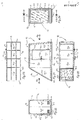
- 1 to 5 and 9 to 20 show a simplified first embodiment of the thermal-solar treatment cabin according to the invention, which is designated in its entirety by 10.
- the cabin 10 comprises a rectangular base plate 11, vertically arranged, lateral longitudinal walls 12, 13 with a trapezoidal, but differently inclined, upwardly converging sides, and a rectangular transverse wall 14 for connecting the less inclined side of each longitudinal wall 12, 13 and the bottom plate 11.
- a rigid, rectangular flat roof 15 is connected to the upper sides of the longitudinal walls 12, 13 and the transverse wall 14, while the remaining opening, which by the free transverse side of the bottom plate 11 and the roof 15 and the more inclined sides of the Longitudinal walls 12, 13 by a correspondingly dimensioned fixed window 16 is closed with a rectangular window frame 16.1, this window above, ie; the inclination of the mentioned sides of the longitudinal walls is accordingly inclined towards the interior of the cabin 10 (Fig. 1 to 5).
- This support structure consisting of vertical supports 10.1 and cross members 10.2 and spars 10.3 cooperates with a corresponding support and reinforcement frame for base plate 11 consisting of cross members 11.1 and spars 11.2 (FIGS. 3 and 9).
- the frame 16.1 of the glass window 16 is articulated according to a modified embodiment with its lowermost cross member 16.3 by means of a hinge 17 with hinge bolts 17.1 directed transversely to the base plate according to a horizontal axis YY to the base plate.
- the window frame 16.1 can be pivoted about the aforementioned axis YY in a vertical longitudinal plane of the cabin 10.
- the window frame 16.1 has locking bolts 16.5 at the ends of its uppermost traverse 16.4, the slides 16.6 of which can be displaced in their guides according to a horizontal axis ZZ parallel to the axis YY of the hinge bolts 17.1 (FIG. 10).
- This locking slide 16.6 engage in their advanced position from the guides in two corresponding axially opposite and symmetrically arranged with respect to the vertical longitudinal center ne ne blind holes, for example 12.1 (Fig. 11), which arc inside the longitudinal walls 12, 13 in a circle with the center point on the mentioned axis YY and with a radius corresponding to the distance between this axis YY and the axis ZZ of the locking slide 16.6 (only the arrangement is in the figures tion of the blind holes 12.1 visible in one longitudinal wall 12).
- the window frame 16.1 with the glass window 16 can be pivoted into several positions with different angles of inclination and can be determined by means of the bolt 16.5 or the bolt slide 16.6 under their engagement in the corresponding blind holes, for example 12.1 of the longitudinal walls of the cabin 10 in the selected pivot position.
- the glass window 16 is shown with fully drawn lines in its swivel position which is minimally inclined with respect to the vertical and with dashed lines in its maximally inclined snowing position.
- a rectangular through opening 12.2 (Fig. 1, 9, 10) is provided, which can be closed by means of a correspondingly dimensioned outer door leaf 12.3 with a locking handle 12.4.
- This door leaf can be pivoted in the open or closed position by means of hinges 12.5 with vertically directed hinge bolts, the hinge leaves of which are fastened on the outside to the longitudinal wall 12 and on the door leaf 12.3 (FIGS. 1, 17, 18).
- sealing means 12.6 In order to achieve a safe seal against the ingress of air, dust, water and other weather influences when the door is closed, sealing means 12.6 with a tubular profile 12.7, which slightly protrudes when the door 12.3 is open, are made between the door leaf 12.3 and the wall opening 12.2 along the circumference resilient material attached to the outside of the opening 12.2 (Fig. 17).
- the tubular profile 12.7 of this sealing means 12.6 is elastically deformed when the door leaf 12.3 is closed and brings about the desired sealing under tight contact with the inside of the door leaf circumference (FIG. 18).
- the tubular sealing means 12.6 consist of a simple one Strips of elastic material, for example a rubber band, which is bent in length approximately in the manner of a tubular hose and is fastened with its inwardly directed longitudinal edges by means of screws to the circumference of the wall opening 12.2 of the cabin 10.
- sealing means 16.7 with tubular profile 16.8 in a design similar to the mentioned sealing means 12.6 by means of continuous screws with washer on the inside along the side rails 16.9, 16.10 of the pivotable window frame 16.1 with tight contact of the tubular profile 16.8 against them Inside of the longitudinal walls 12, 13 of the Kabi ne 10 attached.
- a strip 16.11 of rubber-elastic material along the entire cross member 16.3 is between the hinge leaves 17 and the inside of the base plate 11 and the bottom cross member 16.3 of the swivel frame 16.1 attached in the manner of an elongated flexible hinge for connecting the swivel frame 16.1 to the base plate 11.
- This elastic strip 16.11 is also fastened, for example by means of screws, to the cross member 16.3 of the swivel frame 16.1 and the base part 11 in the space between the hinges 17 (FIG. 10) in order to achieve a snug fit against these parts along its entire length.
- the elastic strip 16.11 therefore forms an effective seal between the articulation parts in cooperation with the hinges 17 during the pivoting movement of the window frame 16.1.
- strip-shaped sealing means 16.12 of flexible, impermeable dimensions between the uppermost cross member 16.4 of the swivel frame 16.1 and the flat roof 15 used material.
- This sealing strip 16.12 has a width which is approximately the distance between the free transverse side of the roof 15 and the vertical transverse plane, which in the interior of the cabin 10 limits the position of the window frame 16.1 pivoted in by the greatest angle of inclination (shown by broken lines in FIG. 11) Position).
- the strip 16.12 is attached, for example, by means of screws with one of its longitudinal edges to the underside of the roof 15 of the entire transverse width.
- This strip is set back from the free crossmember of the roof 15 by a smaller distance than the width of the strip 16.12, while on the other longitudinal edge of the strip 16.12 is fixed, for example by means of screws, to the top of the uppermost traverses 16.4 of the pivoting frame 16.1. Due to this arrangement, the sealing strip 16.12 accompanies the frame 16.1 in its pivoting movement without hindering this pivoting movement about the axis YY, and thereby provides a secure seal against the ingress of dust, air, water and weather influences between the top crossmember 16.4 of the frame 16.1 and the roof 15. Instead of such a rubber-elastic strip can of course also a sufficiently strong, against air, water and the like. impermeable fabric seal can be used.
- ventilation hoods 14.1 are provided in the transverse wall. These ventilation hoods 14.1 (FIGS. 9, 15, 16) each consist of a slot-like opening 14.2, which is protected by a corresponding grille 14.3 and whose opening width can be adjusted by hand by suitable means 14.4 to regulate the air flow.
- These means 14.4 comprise a cover 14.5 which can be displaced on the transverse wall 14 in horizontal guides 14.6 (FIGS. 15, 16). 16, these means 14.4 are shown with solid lines in the closed state, in which the cover 14.5 is completely pushed into its guides 14.6, so that the opening 14.2 is closed by the cover and each air passage is prevented; The dashed lines, on the other hand, indicate the cover 14.5 in its maximum extended position from the guides 14.6, in which the means 14.4 are completely open and the air flow through the opening 14.2 is fully released.
- the treatment cabin 10 is with a known, not shown interior lighting, which is powered by a battery with electrical power, see ver.
- the cabin 10 can be divided into a plurality of interiors, e.g. also to separate a changing room.
- FIG. 6 to 8 show a second embodiment of the thermal-solar treatment cabin according to the invention, in which, for easier transportation and orientation with respect to the incident sun rays S, the cabin 10, in the manner of a trailer vehicle, has a driving axle 20 with tires 21 and a front, horizontally oriented rigid Has frame 30.
- This frame is firmly connected to the base part 11 and is designed as a drawbar for connection to a (not shown) towing vehicle.
- this cabin has 10 foldable trestles 40 which support the cabin after the cabin has been removed from the towing vehicle.
- the driving Axis 20 is connected in a known manner to the base part 11 in a position set back relative to the center of gravity of the load with the interposition of spring suspensions, for example leaf springs 22.
- the frosted wheels 21 are partially protected by fenders 23, which are fastened to the bottom part 11.
- the front rigid frame 30 has, in the manner of conventional drawbars for trailers, at least one crossbeam (not shown) which is fastened to the underside of the base plate 11, and two spars 31 which are firmly connected to this crossbeam and diverge in the form of a fork from the drawbar with the cabin 10 connect.
- This cross member and the spars 31 of the frame 30 are formed by solid metal profiles, for example square profiles.
- the bars 31 of the frame 30 are provided at the free end with a pull hook 32 for connection to the towing vehicle.
- the front frame 30 can be articulated on the base part 11 and pivoted in a vertical longitudinal plane of the cabin 10.
- the foldable support brackets 40 are formed by two swivel arms 41 with feet 42 and are hinged at their upper end to support forks 43 which are symmetrically spaced from the center line of the cables and near the front end of the base part 11.
- the articulation of the swivel arms 41 in the support forks 43 is carried out by means of horizontally and transversely to the cabin 10 such angeord Neten bolts 44 that the arms 41 are pivotable in the vertical longitudinal planes of the cabin 10.
- Each swivel arm consists of two telescopically displaceable tube pieces, each with a plurality of radially and coaxially arranged holes for pushing through a locking pin in order to set a more or less large length of the telescopically displaceable tube pieces of each swivel arm 41.
- the swivel arms 41 folded in the position of use can be adjusted in length depending on the nature of the base. Except for use, the swivel arms 41 are in a position tilted against the underside of the bottom plate 11 by means of their locking pins mentioned, which also engage in holes 43.1 provided in the support 43 (FIG. 6) with axes parallel to the pivot bolts 44, can be fixed.
- the structure of the cabin 10 according to this embodiment is entirely the same as that described and illustrated with reference to the first embodiment.
- 21 to 37 show a third embodiment of the thermal-solar treatment cabin according to the inven tion, wherein the cabin 10 consists of parts that can be dismantled and reassembled in a simple manner.
- the Bodenplat te 11 the two longitudinal walls 12, 13, the transverse wall 14 and the roof 15 are formed by attachable rectangular plate parts 11P, 12P, 13P, 14P and 15P; for the longitudinal walls 12, 13 a triangular plate part 12P1, 13P1 are also provided at one end and a trapezoidal part 12P2, 13P2 at the other end.
- These plate parts are assembled either by butt connection by means of brackets 50 and screws 51 (Fig. 36), or by a form fit by means of overlap and screws 52 (Fig. 35), or by a form fit by means of mortise and tenon (Fig. 37), whereby a connection has the advantage of a better seal through positive locking. Accordingly, according to FIGS.
- the support structure for the cabin 10 consisting of supports 10.1, crossbeams 10.2 and spars 10.3 and the Ver consisting of crossbeams 11.1 and spars 11.2 stiffening frame for the base plate 11 assembled by detachable connection of metal profiles with each other and with the individual plate parts using screws with or without nuts (Fig. 31 to 34).
- an additional frame consisting of supports 10.5 and crossbeams 10.6 is provided for the transverse wall 14 for stronger reinforcement of the supporting frame.
- This additional frame is detachably connected to the Hol men 10.3 and the spars 10.4, which serve for further connec tion of the longitudinal walls 12, 13 with the base plate 11 and also consists of metal profiles that are detachably joined together and with the above-mentioned structural parts.
- a frame 16i made of metal profiles also reinforces the swivel frame 16.1 of the glass window 16 (FIG. 29).
- the individual components of the cabin 10 according to this embodiment are sufficiently clear from the figures, so that a further description of the same is unnecessary.
- FIGS. 38 to 41 A fourth embodiment of the treatment booth according to the invention is shown in FIGS. 38 to 41 and designated 60 in its entirety.
- the cabin 60 is designed in the manner of a straight circular cylinder which is cut through an inclined plane (sectional area DD in FIG. 38). This cut surface is based on a diameter of the upper base surface and extends to just above the lower base surface of the cylinder (FIGS. 38 and 41). The intersection of this sectional plane with the outer surface of the cylinder is an approximately semi-elliptical profile (Fig. 40).
- the cabin 60 has a circular base plate 61 and a vertical jacket wall 62 with a window opening 63 which extends essentially over the entire height of the cabin and, as mentioned, has an approximately semi-elliptical shape.
- a rigid, semicircular flat roof 64 is firmly connected to the jacket wall and to the diameter side 64.1 which delimits the above-mentioned window opening 63 in the jacket wall 62 at the top (FIG. 41).
- the window opening formed between the jacket wall 62 and the roof 64 is encompassed along its circumference by a continuous frame 65.1 which projects into the opening in the manner of a flange and to which a correspondingly shaped window glazing 65.2 is fastened.
- this embodiment also has a correspondingly large window 65 which is inclined inwards at the top.
- this window 65 can also have a swivel frame which is articulated on the diameter side 64.1 of the roof 64 and is provided along its circumference with suitable sealing means.
- the cabin has a pivoting window equipped with lens glazing so that the incident sun rays can be appropriately focused by changing the angle of inclination of the window and the effects of the sun radiation can thereby be controlled in a manner appropriate to the treatment.
- the sealing means 16.7 provide a tight seal against air, dust, water and the like. between the side rails 16.9, 16.10 of the swivel frame 16.1 for the glass window 16 and the side walls 12, 13 of the cabin 10 and this also during the swivel movement of the frame 16.1 about the axis Y-Y by the sliding contact ih-. res tubular sealing body 16.8 against the inner surface of the adjacent side wall despite the high elastic deformability of this tubular sealing body.
Landscapes
- Health & Medical Sciences (AREA)
- Engineering & Computer Science (AREA)
- Biomedical Technology (AREA)
- Life Sciences & Earth Sciences (AREA)
- Nuclear Medicine, Radiotherapy & Molecular Imaging (AREA)
- Radiology & Medical Imaging (AREA)
- Pathology (AREA)
- Animal Behavior & Ethology (AREA)
- General Health & Medical Sciences (AREA)
- Public Health (AREA)
- Veterinary Medicine (AREA)
- Body Structure For Vehicles (AREA)
- Devices For Medical Bathing And Washing (AREA)
- Radiation-Therapy Devices (AREA)
Abstract
Description
Die Erfindung betrifft eine thermisch-solare Behandlungs kabine für Personen und/oder Tiere zur Behandlung durch die Wikrung der Sonnenstrahlung, insbesondere für solare Sauna-Bäder.The invention relates to a thermal-solar treatment cabin for people and / or animals for treatment by the Wikrung solar radiation, especially for solar sauna baths.
Der Erfindung liegt die Aufgabe zugrunde, eine Kabine der genannten Art zu schaffen, die eine wirksame Behandlung von Personen und/oder Tieren durch direkte und/oder indirekte Einwirkung der Sonnenstrahlen vor allem zu Heilzwecken, wie z.B. zur heliotherapeutischen Behandlung, aber auch zu allgemeinen Zwecken der Hydiene und der Körperpflege sowie zur Verbesserung und Rationalisie rung der Zucht von Haustieren und/oder in der Gefangenschaft lebenden Tieren. Dabei soll gemäss der Erfidnung die Behandlungskabine eine rationelle Ausnutzung der Wir kung der Lichtstrahlen (insbesondere der ultravioletten und infraroten Strahlen) und/oder der Wärmeenergie der Sonnenstrahlen unter steuerbaren Bedingungen und mit hohem Wirkungsgrad ermöglichen, und im einzelnen in dem zu behandelnden Subjekt sowohl die Pigmentierung der Haut als auch die Schweissausscheidung durch die Schweiss - drüsen fördern; dadurch soll dem zu behandelnden Subjekt die Möglichkeit geboten sein, in ein und demselben Raum mit ein und derselben Behandlung die wohltuen den und heilbringenden Resultate zu erreichen, die sonst durch getrennte Behandlungen und in verschiedenen Ortlichkeiten (wie Solarium, Sauna u.a.) erzielt werden können, oder aber die Alternative geboten werden, jeweils eine gewünschte spezifische Behandlungsart stets im selben Behandlungsraum zu wählen.The invention has for its object to provide a cabin of the type mentioned, the effective treatment of people and / or animals by direct and / or indirect action of the sun's rays especially for healing purposes, such as for heliotherapeutic treatment, but also for general purposes Hydiene and body care as well as to improve and rationalize the breeding of pets and / or animals living in captivity. Thereby, according to the invention, the treatment cabin should enable a rational use of the effect of the light rays (in particular the ultraviolet and infrared rays) and / or the thermal energy of the sun rays under controllable conditions and with high efficiency, and in particular in that Treating subject promote both skin pigmentation and sweat excretion through the sweat glands; This should give the subject to be treated the opportunity to achieve the beneficial and healing results in one and the same room with one and the same treatment, which can otherwise be achieved through separate treatments and in different locations (such as solarium, sauna etc.), or the alternative is offered to always choose a desired specific type of treatment in the same treatment room.
Ausserdem soll die erfindungsgemässe Behandlungskabine bequem verfahrbar und/oder orientierbar sein, damit deren Standort und/oder Stellung gegenüber der Sonneneinstrahlung nach Bedarf geändert werden können.In addition, the treatment booth according to the invention should be easy to move and / or orientate so that its location and / or position in relation to the solar radiation can be changed as required.
Endlich soll die erfindungsgemässe Behandlungskabine einfach in ihrem Aufbau und in der Bedienung sowie zuverlässig und sicher in ihrer Benutzung sein.Finally, the treatment booth according to the invention should be simple in its construction and operation, and reliable and safe in its use.
Dieser Aufgabenstellung entsprechend ist die erfindungs gemässe Behandlungskabine dadurch gekennzeichnet (Patentanspruch 1) durch wenigstens ein Glasfenster, das oben gegen den Innenraum der Kabine hin derart geneigt ist, dass die Sonnenstrahlen zweckentsprechend in den Innenraum der Kabine einfallen und so auf das zu behandelnde Subjekt ihre wohltuenden Wirkungen voll entfalten können.According to this task, the treatment booth according to the invention is characterized (claim 1) by at least one glass window which is inclined at the top towards the interior of the booth in such a way that the sun's rays fall appropriately into the interior of the booth and so benefit the subject to be treated Can fully develop effects.
Mit besonderem Vorteil ist das oben nach innen geneigte Galsfenster im Neigungswinkel wahlweise einstellbar aus gebildet und besitzt Mittel, um das Fenster in der eingestellten Neigung festzusetzen (Anspruch 2).It is particularly advantageous that the Gals window, which is inclined inwards at the top, is optionally adjustable in the angle of inclination and has means for fixing the window in the set inclination (claim 2).
Gemäss einem anderen Merkmal der Erfidnung sind Abdichtungsmittel zwischen dem Glasfenster, der Tür und den zugeordneten Wandteilen der behandlungskabine vorgese - hen, um durch Witterungseinflüsse bedingtes Eindringen von Luft, Wasser, Staub u.dgl. zu verhindern (Anspruch 3).According to another feature of the invention, sealing means are provided between the glass window, the door and the associated wall parts of the treatment cabin in order to prevent air, water, dust and the like from penetrating due to weather conditions. to prevent (claim 3).
Weitere Einzelheiten und Merkmale der Erfindung ergeben sich aus den Unteransprüchen 4 bis 7.Further details and features of the invention emerge from
Die Erfindung wird nachstehend anhand der Zeichnung und der darin dargestellten Ausführungsformen näher erläutert. Es zeigen:
- Fig. 1 bis 3 eine Seitenansicht, eine Ansicht von oben und eine Ansicht von unten eines ersten, vereinfachten Ausführungsbeispiels der erfindungsgemäs sen Behandlungskabine;
- Fig. 4 und 5 jeweils eine Ansicht in Richtung des Pfeiles F bzw. F1 der Fig. 1;
- Fig. 6, 7 und 8 eine Seitenansicht, eine Ansicht von oben und eine Ansicht in Richtung des Pfeiles F2 der Fig. 6 einer zweiten Ausführungsform der erfindungsgemässen Behandlungskabine;
- Fig. 9 einen Längsschnitt längs der Linie IX-IX der Fig. 4, wobei das Glasfenster in seiner Neigung einstellbar ist;
- Fig. 10 einen Querschnitt längs der Linie X-X der Fig.9;
- Fig. 11 die Einzelheit A der Fig. 9 in grösserem Massstab;
- Fig. 12 einen teilweisen Querschnitt längs der Linie XII-XII der Fig.11;
- Fig. 13 die Einzelheit B der Fig. 9 in grösserem Massstab;
- Fig. 14 eine Ansicht in Richtung des Pfeiles F3 der Fig. 13;
- Fig. 15 die Einzelheit C der Fig. 9;
- Fig. 16 eine Ansicht in Richtung des Pfeiles F4 der Fig. 15;
- Fig. 17 einen Schnitt längs der Linie XVII-XVII der Fig. 9 in grösserem Masstab;
- Fig. 18 eine dem Schnitt gemäss Fig. 17 ähnliche Darstellung, worin jedoch die Tür der Behandlungs kabine gemäss Fig. 9 in halb offenem Zustand gezeigt ist;
- Fig. 19 einen Querschnitt durch die Abdichtungsmittel zwischen Fenster, Tür und den zugeordneten Wandteilen der Kabine gemäss Fig. 9 in grösserem Masstab;
- Fig. 20 einen Querschnitt längs der Linie XX-XX der Fig. 9 in grösserem Masstab;
- Fig. 21 bis 23 eine Seitenansicht, eine Ansicht von oben und eine Ansicht von unten einer dritten Ausführungsform der erfindungsgemässen Behandlungskabine;
- Fig. 24 und 25 jeweils eine Ansicht in Richtung des Pfei les F5 bzw. F6 der Fig. 21;
- Fig. 26 einen Längsschnitt gemäss der Linie XXVI-XXVI der Fig. 24, wobei jedoch nur das Traggerippe der Behandlungskabine gemäss Fig. 24 samt der Bodenversteifung gezeigt ist;
- Fig. 27 und 28 jeweils eine Ansicht von unten bzw. von oben des Traggerippes der Kabine gemäss Fig. 26, wobei jedoch die Bodenversteifung der gr8sseren Klarheit wegen ausgelassen ist;
- Fig. 29 eine Ansicht in Richtung des Pfeiles F7 der Fig. 26 des Tragrahmens für das Galsfenster der Kabi ne gemäss Fig. 24, in der dieser Tragrahmen der Klarheit halber nicht gezeigt ist;
- Fig. 30 eine Ansicht von unten der Versteifung des die Kabine gemäss Fig. 26 tragenden Bodens;
- Fig. 31 eine Detail-Ansicht in grösserem Masstab und im Querschnitt längs der Linie XXXI-XXXI der Fig. 26, wobei hier auch die im einzelnen in Fig. 26 nicht gezeigten Wandteile und deren Verbindungs mittel dargestellt sind;
- Fig. 32 eine Ansicht in Richtung des Pfeiles F8 der Fig. 31;
- Fig. 33 einen Schnitt gemäss der Linie XXXIII-XXXIII der Fig. 26, ähnlich dem Schnitt der Fig. 31;
- Fig. 34 eine Ansicht in Richtung des Pfeiles F9 der Fig. 33;
- Fig. 35 bis 37 Detail-Ansichten in grösserem Masstab und im Querschnitt verschiedener Ausführungsformen der Verbindungsmittel für aneinanderge setzte Wandteile;
- Fig. 38 eine Ansicht eine vierten Ausführungsform der erfindungsgemässen Behandlungskabine;
- Fig. 39 und 40 jeweils eine Ansicht in Richtung des Pfeiles F10 bzw. F11 der Fig. 38, und
- Fig. 41 eine Ansicht von oben der Behandlungskabine der Fig. 36.
- Figures 1 to 3 is a side view, a view from above and a view from below of a first, simplified embodiment of the treatment booth according to the invention.
- FIGS. 4 and 5 each show a view in the direction of the arrows F and F1 of FIG. 1;
- 6, 7 and 8 are a side view, a view from above and a view in the direction of arrow F2 of FIG. 6 of a second embodiment of the treatment cabin according to the invention;
- 9 shows a longitudinal section along the line IX-IX of FIG. 4, the inclination of the glass window being adjustable;
- Figure 10 is a cross section along the line XX of Figure 9;
- 11 shows detail A of FIG. 9 on a larger scale;
- Fig. 12 is a partial cross section along the line XII-XII of Fig.11;
- 13 shows detail B of FIG. 9 on a larger scale;
- Fig. 14 is a view in the direction of arrow F3 of Fig. 13;
- Fig. 15 shows the detail C of Fig. 9;
- FIG. 16 is a view in the direction of arrow F4 in FIG. 15;
- 17 shows a section along the line XVII-XVII of FIG. 9 on a larger scale;
- FIG. 18 shows an illustration similar to the section according to FIG. 17, but showing the door of the treatment cabin according to FIG. 9 in a half-open state;
- 19 shows a cross section through the sealing means between the window, door and the associated wall parts of the cabin according to FIG. 9 on a larger scale;
- 20 shows a cross section along the line XX-XX of FIG. 9 on a larger scale;
- 21 to 23 a side view, a view from above and a view from below of a third embodiment of the treatment booth according to the invention;
- 24 and 25 are each a view in the direction of the arrows F5 and F6 of FIG. 21;
- FIG. 26 shows a longitudinal section along the line XXVI-XXVI of FIG. 24, but only the support frame of the treatment cabin according to FIG. 24 including the floor reinforcement is shown;
- 27 and 28 each show a view from below and from above of the supporting structure of the cabin according to FIG. 26, but the stiffening of the floor has been omitted for the sake of greater clarity;
- 29 is a view in the direction of arrow F7 of FIG. 26 of the support frame for the Gals window of the cabins according to FIG. 24, in which this support frame is not shown for the sake of clarity;
- 30 is a bottom view of the stiffening of the floor supporting the cabin according to FIG. 26;
- Fig. 31 is a detailed view on a larger scale and in cross section along the line XXXI-XXXI of Fig. 26, here also the wall parts not shown in detail in Fig. 26 and their connecting means are shown;
- FIG. 32 is a view in the direction of arrow F8 in FIG. 31;
- 33 shows a section along the line XXXIII-XXXIII of FIG. 26, similar to the section of FIG. 31;
- Fig. 34 is a view in the direction of arrow F9 of Fig. 33;
- Fig. 35 to 37 detail views on a larger scale and in cross section of different embodiments of the connecting means for mutually set wall parts;
- 38 is a view of a fourth embodiment of the treatment booth according to the invention;
- 39 and 40 are each a view in the direction of arrow F10 and F11 of FIG. 38, and
- 41 is a top view of the treatment cabin of FIG. 36.
Die in den Zeichnungen dargestellten Teile mit gleich artigem Aufbau und gleichartiger Funktion sind in den einzelnen Figuren mit gleichen Bezugszeichen versehen.The parts shown in the drawings with the same structure and function are provided with the same reference numerals in the individual figures.
Die Fig. 1 bis 5 und 9 bis 20 zeigen eine vereinfachte erste Ausführungsform der erfindungsgemässen, thermisch -solaren Behandlungskabine, die in ihrer Gesamtheit mit 10 bezeichnet ist.1 to 5 and 9 to 20 show a simplified first embodiment of the thermal-solar treatment cabin according to the invention, which is designated in its entirety by 10.
Die Kabine 10 umfasst eine rechteckige Bodenplatte 11, senkrecht angeordnete, seitliche Längswände 12, 13 mit trapezförmigem-, jedoch verschieden geneigte, nach oben zusammenlaufende Seiten aufweisendem Umfang, und eine rechteckige Querwand 14 zur Verbindung der weniger stark geneigten Seite jeder Längswand 12, 13 und der Bodenplatte 11. Ein steifes, rechteckiges Flachdach 15 ist mit den oberen Seiten der Längswände 12, 13 und der Querwand 14 verbunden, während die verbliebe Offnung, die durch die nach freie Querseite der Bodenplatte 11 und des Daches 15 sowie die stärker geneigeten Seiten der Längswände 12, 13 durch ein entsprechend bemessenes fest angeordnetes Fenster 16 mit rechteckigem Fensterrahmen 16.1 geschlossen wird, wobei dieses Fenster oben, d.h; der eigung der erwähnten Seiten der Längswände ent sprechend nach dem Innenraum der Kabine 10 hin geneigt ist (Fig. 1 bis 5). Die Strukturverbindung der Seitenwände 12, 13, 14 und des Daches 15 sowie die Verteilung der Aufbaulasten sind durch ein Traggerippe verwirklicht. Dieses aus senkrechten Stützen 10.1 und damit verbundenen Traversen 10.2 und Holmen 10.3 bestehende Traggerippe wirkt mit einem entsprechenden aus Traversen 11.1 und Holmen 11.2 bestehenden Trag- und Versteifungsrahmen für die Bodenplatte 11 zusammen (Fig. 3 und 9).The
Wie aus den Fig. 9 und 10 hervorgeht, ist der Rahmen 16.1 des Glasfensters 16 gemäss einer abgewandelten Ausführung mit seiner untersten Traverse 16.3 mittels Schar niere 17 mit gemäss einer waagerechten Achse Y-Y quer zur Bodenplatte gerichteten Scharnierbolzen 17.1 an die Bodenplatte angelenkt. Dadurch ist der Fensterrahmen 16.1 um die erwähnte Achse Y-Y in einer senkrechten Längsebene der Kabine 10 schwenkbar. Ausserdem besitzt der Fensterrahmen 16.1 an den Enden seiner obersten Traverse 16.4 Feststellriegel 16.5, deren Schieber 16.6 in ihren Führungen gemäss einer zur Achse Y-Y der Scharnierbolzen 17.1 parallelen, waagerechten Achse Z-Z (Fig. 10) verschiebbar sind. Diese Riegelschieber 16.6 greifen in ihrer aus den Führungen vorgeschobenen Stellung wahlweise in jeweils zwei entsprechende, axial gegenüberliegende und symmetrisch gegenüber der vertikalen Längsmittelebe ne angeordnete Blindlöcher, z.B. 12.1 (Fig. 11) ein, die innenseitig in den Längswänden 12, 13 in einem Kreis bogen mit dem Mittelpunkt auf der erwähnten Achse Y-Y und mit einem Radius entsprechend dem Abstand zwischen dieser Achse Y-Y und der Achse Z-Z der Riegelschieber 16.6 angeordnet sind (in den Figuren ist nur die Anordnung der Blindlöcher 12.1 in der einen Längswand 12 sichtbar). Daher ist der Fensterrahmen 16.1 mit dem Glasfenster 16 in mehrere Stellungen mit unterschiedli chem Neigungswinkel verschwenkbar und mittels der Riegel 16.5 bzw. der Riegelschieber 16.6 unter deren Eingriff in die entsprechenden Blindlöcher z.B. 12.1 der Längswände der Kabine 10 in der gewählten Schwenkstellung feststellbar. In den Fig. 9 und 11 ist das Glas - fenster 16 mit vollausgezogenen Linien in seiner minimal gegenüber der Vertikalen geneigten Schwenkstellung und mit gestrichelten Linien in seiner maximal geneigten Schnwekstellung dargestellt.As can be seen from FIGS. 9 and 10, the frame 16.1 of the
In der Längswand 12 der Kabine 10 ist eine rechteckige Durchgangsöffnung 12.2 (Fig. 1, 9, 10) vorgesehen, die mittels eines entsprechend bemessenen Aussentürblat tes 12.3 mit Riegelgriff 12.4 verschliessbar ist. Dieses Türblatt ist mittels Scharniere 12.5 mit senkrecht gerichteten Scharnierbolzen, deren Scharnierblätter aussen an der Längswand 12 und am Türblatt 12.3 befestigt sind, in Offen- bzw. Schliesstellung schwenkbar (Fig. 1, 17, 18). Um bei geschlossener Tür eine gegen Eindringen von Luft, Staub, Wasser und andere Witterungs einflüsse sichere Abdichtung zu erzielen, sind zwischen dem Türblatt 12.3 und der Wandöffnung 12.2 dem Umfang entlang verlaufende Abdichtungsmittel 12.6 mit rohrförmigem - bei offener Tür 12.3 etwas vorstehendem - Profil 12.7 aus elastisch nachgiebigem Material an der Aussenseite der Öffnung 12.2 angebracht (Fig. 17). Das rohrförmige Profil 12.7 dieser Abdichtungsmittel 12.6 wird beim Schliessen des Türblattes 12.3 elastisch verformt und bewirkt unter dichter Anlage gegen die Innenseite des Türblattumfangs die gewünschte Abdichtung (Fig. 18). Bei dem dargestellten Ausführungsbeispiel bestehen die rohrförmigen Abdichtungsmittel 12.6 aus einem einfachen Streifen aus elastischem Material, z.B. einem Gummiband, das seiner Länge nach etwa nach Art eines Rohrschlauches umgebogen und mit seinen nach innen gerichteten Längsrändern mittels Schrauben am Umfang der Wandöffnung 12.2 der Kabine 10 befestigt wird.In the
Wie die Fig. 1g und 20 zeigen, sind Abdichtungsmittel 16.7 mit rohrförmigem Profil 16.8 in ähnlicher Ausführung wie die erwähnten Abdichtungsmittel 12.6 mittels'durchgehender Schrauben mit Beilegscheibe innenseitig entlang der Seitenholme 16.9, 16.10 des schwenkbaren Fensterrahmens 16.1 unter dichter Anlage des rohrförmigen Profils 16.8 gegen die Innenseite der Längswände 12, 13 der Kabi ne 10 befestigt.1g and 20 show, sealing means 16.7 with tubular profile 16.8 in a design similar to the mentioned sealing means 12.6 by means of continuous screws with washer on the inside along the side rails 16.9, 16.10 of the pivotable window frame 16.1 with tight contact of the tubular profile 16.8 against them Inside of the
Wie ausserdem aus den Fig. 9, 10 und insbesondere den Fig. 13, 14 hervorgeht, ist zwischen den Scharnierblättern 17 und der Innenseite der Bodenplatte 11 und der untersten Traverse 16.3 des Schwenkrahmens 16.1 ein Strei fen 16.11 aus gummielastischem Material der gesamten Traverse 16.3 entlang nach Art eines langgestreckten flexiblen Scharniers zur Verbindung des Schwenkrahmens 16.1 mit der Bodenplatte 11 angebracht. Dieser elastische Streifen 16.11 ist ausserdem z.B. mittels Schrauben gegenüber der Traverse 16.3 des Schwenkrahmens 16.1 und dem Bodenteil 11 in dem Zwischenraum zwischen den Scharnieren 17 (Fig. 10) befestigt, um eine satte Anlage an diese Teile seiner gesamten Länge entlang zu erzielen. Der elastische Streifen 16.11 bildet daher eine wirksame Andichtung zwischen den Anlenkungsteilen unter Mitwirkung mit den Scharnieren 17 während der Schwenkbewegung des Fensterrahmens 16.1. Wie besonders die Fig. 11 und 12 zeigen, sind ausserdem zwischen der obersten Traverse 16.4 des Schwenkrahmens 16.1 und dem Flachdach 15 ebenfalls streifenförmige Abdichtungsmittel 16.12 aus flexiblem undurchlässigem Material eingesetzt. Dieser Abdichtungsstreifen 16.12 besitzt eine Breite, die etwa dem Abstand zwischen der freien Querseite des Daches 15 und der senkrechten Quer ebene, die im Inneren der Kabine 10 die um den grössten Neigungswinkel eingeschwenkte Stellung des Fensterrahmens 16.1 begrenzt (mit gestrichelten Linien in Fig. 11 dargestellte Stellung) entspricht. Der Streifen 16.12 ist z.B. mittels Schrauben mit einem seiner Längsränder an die Unterseite des Daches 15 der gesamten Querbreite ent lang befestigt. Dabei ist dieser Streifen gegenüber der freien Traverse des Daches 15 um einen im Vergleich zur Breite des Streifens 16.12 geringeren Abstand zurückgesetzt, während am anderen Längsrand der Streifen 16.12 z.B. mittels Schrauben an der Oberseite der obersten Tra verse 16.4 des Schwenkrahmens 16.1 festgesetzt ist. Auf Grund dieser Anordnung begleitet der Abdichtungsstreifen 16.12 den Rahmen 16.1 in seiner Schwenkbewegung, ohne dabei diese Schwenkbewegung um die Achse Y-Y zu behindern, und bewirkt dadurch eine sichere Abdichtung gegen das Eindringen von Staub, Luft, Wasser u. a. Witterungseinflüssen zwischen der obersten Traverse 16.4 des Rahmens 16.1 und dem Dach 15. Anstatt eines derartigen gummielastischen Streifens kann selbstverständlich auch eine hinreichend starke, gegen Luft, Wasser u.dgl. undurchlässige Gewebedichtung eingesetzt werden.9, 10 and in particular FIGS. 13, 14, a strip 16.11 of rubber-elastic material along the entire cross member 16.3 is between the hinge leaves 17 and the inside of the
Zur steuerbaren Klimatisierung und Belüftung des Innebraumes der Kabine 10 sind in der Querwand 14 Belüftungs hauben 14.1 (im dargestellten Beispiel der Fig. 5: zwei) vorgesehen. Diese Belüftungshauben 14.1 bestehen (Fig. 9, 15, 16) je aus einer schlitzartigen Öffnung 14.2, die durch ein entsprechendes Gitter 14.3 abgeschützt und in ihrer Öffnungsweite zur Regelung des Luftdurchflusses durch geeignete Mittel 14.4 von Hand einstellbar ist.For controllable air conditioning and ventilation of the interior of the
Diese Mittel 14.4 umfassen einen satt an der Querwand 14 in waagerechten Führungen 14.6 verschiebbaren Deckel 14.5 (Fig. 15, 16). In Fig. 16 sind diese Mittel 14.4 mit ausgezogenen Linien im geschlossenen Zustand dargestellt, in dem der Deckel 14.5 vollständig in seine Führungen 14.6 eingeschoben ist, so dass die Öffnung 14.2 vom Deckel verschlossen und jeder Luftdurchlass unterbunden ist; mit gestrichelten Linien ist hingegen der Deckel 14.5 in seiner maximalen Auszugsstellung aus den Führungen 14.6 angedeutet, in der die Mittel 14.4 vollständig offen sind und der Luftdurchfluss durch die Öffnung 14.2 in vollem Umfang freigegeben ist.These means 14.4 comprise a cover 14.5 which can be displaced on the
Die Behandlungskabine 10 ist mit einer an sich bekannten, nicht dargestellten Innenbeleuchtung, die von einer Batterie mit elektrischem Strom versorgt wird, ver sehen. Ausserdem kann die Kabine 10 mit in bekannter Weise angeordneten Trennwänden, die feststehend oder beweglich eingebaut sind, zum Abteilen der Kabine in mehrere Innenräume, z.B. auch zum Abtrennen eines Umklei deraumes.The
Die Fig. 6 bis 8 zeigen eine zweite Ausführungsform der erfindungsgemässen thermisch-solaren Behandlungskabine, bei der zur leichteren Beförderung und Orientierung gegegenüber den einfallenden Sonnenstrahlen S die Kabine 10 nach Art eines Anhängerfahrzeugs eine Fahrachse 20 mit bereiften Rädern 21 und ein vorderes, waagerecht ausgerichtetes steifes Gestell 30 aufweist. Dieses Gestell ist mit dem Bodenteil 11 fest verbunden und als Zuggabel zum Anschliessen an ein (nicht dargestelltes) Zugfahrzeug ausgebildet. Ausserdem besitzt diese Kabine 10 klappbare Stützböcke 40, die nach dem Aushängen der Kabine vom Zugfahrzeug die Kabine abstützen. Die Fahrachse 20 ist in bekannter Weise mit dem Bodenteil 11 in gegenüber dem Schwerpunkt der Last zurückversetzter Stellung unter Zwischenlage von gefederten Aufhängungen, z.B. Blattfedern 22, verbunden. Die bereiften Räder 21 sind zum Teil durch Kotflügel 23, die am Bodenteil 11 be festigt sind, abgeschützt. Das vordere steife Gestell 30 besitzt nach Art üblicher Zuggabeln für Anhänger wenigstens eine (nicht dargestellte) Traverse, die an der Unterseite der Bodenplatte 11 befestigt ist, und zwei Holme 31, die mit dieser Traverse fest verbunden sind und gabelförmig auseinanderlaufend die Zuggabel mit der Kabine 10 verbinden. Dabei sind diese Traverse und die Holme 31 des Gestells 30 durch feste Metallprofile, z.B. Vierkantprofile, gebildet. Die Holme 31 des Gestells 30 sind am freien Ende mit einem Zughaken 32 zum Anschliessen an das Zugfahrzeug versehen. In einer abgewandelten Ausführung kann das vordere Gestell 30 am Bodenteil 11 angelenkt und in einer senkrechten Längsebene der Kabine 10 verschwenkbar sein.6 to 8 show a second embodiment of the thermal-solar treatment cabin according to the invention, in which, for easier transportation and orientation with respect to the incident sun rays S, the
Die klappbaren Abstützböcke 40 sind durch zwei Schwenkarme 41 mit Standfüssen 42 gebildet und mit ihrem oberen Ende an symmetrisch von der Mittellinie der Kabile beabstandeten, nahe dem vorderen Ende des Bodenteils 11 unter demselben angeordneten Stützgabeln 43 angelenkt. Die Anlenkung der Schwenkarme 41 in den Stützgabeln 43 erfolgt mittels waagerecht und quer zur Kabine 10 derart angeord neten Bolzen 44, dass die Arme 41 in vertikalen Längsebenen der Kabine 10 schwenkbar sind. Jeder Schwenkarm besteht aus zwei teleskopartig ineinander verschiebbaren Rohrstücken mit jeweils mehreren radial und koaxial angeordneten Löchern zum Durchstecken eines Feststellstiftes, um eine mehr oder weniger grosse Ein- bzw. Auszugslänge der teleskopartig ineinandere verschiebbaren Rohrstücke eines jeden Schwenkarmes 41 einzustellen. Dadurch können die in Gebrauchsstellung geklappten Schwenkarme 41 abhängig von der Beschaffenheit des Standbodens in ihrer Länge eingestellt werden. Ausser Gebrauch sind die Schwenkarme 41 in gegen die Unterseite der Bodenplat te 11 gekippter Stellung mittels ihrer erwähnten Feststellstifte, die dabei auch in entsprechend in den Stütz gabeln 43 vorgesehenen Löchern 43.1 (Fig. 6) mit zu den Anlenkungsbolzen 44 paralleler Achse eingreifen, festsetzbar. Im Ubrigen ist der Aufbau der Kabine 10 gemäss dieser Ausführungsform durchaus gleichartig, wie mit Bezug auf die erste Ausführungsform geschildert und darge stellt, ausgebildet.The foldable support brackets 40 are formed by two
Die Fig. 21 bis 37 zeigen eine dritte Ausführungsform der thermisch-solaren Behandlungskabine gemäss der Erfin dung, worin die Kabine 10 aus in einfacher Weise zerlegbaren und wieder zusammensetzbaren Teilen besteht.21 to 37 show a third embodiment of the thermal-solar treatment cabin according to the inven tion, wherein the
Mit Bezugnahme auf die Fig. 21 bis 25 sind die Bodenplat te 11, die beiden Längswände 12, 13, die Querwand 14 und das Dach 15 durch aneinander ansetzbare rechteckige Plat tenteile 11P, 12P, 13P, 14P und 15P gebildet; für die Längswände 12, 13 sind ausserdem je ein dreieckiger Plat tenteil 12P1, 13P1 an einem Ende und je ein trapezförmiger Teil 12P2, 13P2 am anderen Ende vorgesehen. Diese Plattenteile werden entweder durch Stossverbindung mittels Laschen 50 und Schrauben 51 (Fig. 36), oder durch Formschluss mittels Uberblattung und Schrauben 52 (Fig. 35), oder durch Formschluss mittels Verzapfung bzw. Spundung (Fig. 37) zusammengebaut, wobei eine Verbindung durch Formschluss den Vorteil einer besseren Abdichtung mit sich bringt. Dementsprechend sind gemäss Fig. 26 bis 28 und 30 das aus Stützen 10.1, Traversen 10.2 und Holmen 10.3 bestehende Traggerippe für die Kabine 10 sowie der aus Traversen 11.1 und Holmen 11.2 bestehende Versteifungsrahmen für die Bodenplatte 11 durch lösbare Verbindung von Metallprofilen untereinander und mit den einzelnen Plattenteilen unter Verwendung von Schrauben mit oder ohne Muttern zusammengebaut (Fig. 31 bis 34). Bei dem vorliegenden Beispiel ist zur stärkeren Ver steifung des Traggerippes ein zusätzlicher, aus Stützen 10.5 und Traversen 10.6 bestehender Rahmen für die Quer wand 14 vorgesehen. Dieser Zusatzrahmen ist mit den Hol men 10.3 sowie den Holmen 10.4, die zur weiteren Verbin dung der Längswände 12, 13 mit der Bodenplatte 11 dienen, lösbar verbunden und besteht ebenfalls aus Metallprofilen, die untereinander und mit den erwähnten Aufbauteilen lösbar zusammengefügt sind. Ein Rahmen 16i aus Metallprofilen verstärkt auch den Schwenkrahmen 16.1 des Glasfensters 16 (Fig. 29). Im Übrigen sind die einzelnen Bauteile der Kabine 10 gemäss dieser Ausführungs form hinreichend klar aus den Figuren ersichtlich, so dass sich eine weitere Beschreibung derselben erübrigt.With reference to Figures 21 to 25, the
Eine vierte Ausführungsform der erfindungsgemässen Behandlungskabine ist in den Fig. 38 bis 41 gezeigt und in ihrem Ganzen mit 60 bezeichnet. Die Kabine 60 ist nach Art eines geraden Kreiszylinders, der durch eine schräge Ebene geschnitten ist (Schnittfläche D-D in Fig. 38) ausgebildet ist. Diese Schnittfläche geht von einem Durchmesser der oberen Grundfläche aus und estreckt sich bis kurz oberhalb der unteren Grundfläche des Zylinders (Fig. 38 und 41). Die Uberschneidung dieser Schnittebene mit der Mantelfläche des Zylinders ein etwa halbelliptisches Profil (Fig. 40). Im Einzelnen besitzt die Kabine 60 eine kreisrunde Bodenplatte 61 und eine senkrechte Mantelwand 62 mit einer Fensteröffnung 63, die sich im wesentlichen über die ganze Höhe der Kabine erstreckt und, wie erwähnt, eine etwa halbelliptische Form aufweist. Ein steifes, halbkreisförmiges Flachdach 64 ist mit der Mantelwand und mit der die erwähnte Fensteröffnung 63 in der Mantelwand 62 oben begrenzenden Durchmesserseite 64.1 fest verbunden (Fig. 41). Die zwi schen der Mantelwand 62 und dem Dach 64 gebildete Fen - steröffnung ist ihrem Umfang entlang von einen durchgehenden Rahmen 65.1 umfasst, der flanschenartig in die Öffnung vorsteht und an dem eine entsprechend geformte Fensterverglasung 65.2 befestigt ist. Somit weist auch diese Ausführungsform ein entsprechend gross bemessenes oben nach innen geneigtes Fenster 65 auf. Dieses Fenster 65 kann auch gemäss einer Abwandlung einen Schwenkrahmen aufweisen, der an der Durchmesserseite 64.1 des Daches 64 angelenkt und seinem Umfang entlang mit geeigne ten Abdichtungsmitteln versehen ist.A fourth embodiment of the treatment booth according to the invention is shown in FIGS. 38 to 41 and designated 60 in its entirety. The
Es ist von Vorteil, wenn erfindungsgemäss die Kabine ein mit einer Linsenverglasung bestücktes Schwenkfenster aufweist, damit die einfallenden Sonnenstrahlen durch Veränderung des Neigungswinkels des Fensters zweckmässig fokussiert und dadurch die Wirkungen der Sonnenbestrahlung behandlungsgerecht gesteuert werden können.It is advantageous if, according to the invention, the cabin has a pivoting window equipped with lens glazing so that the incident sun rays can be appropriately focused by changing the angle of inclination of the window and the effects of the sun radiation can thereby be controlled in a manner appropriate to the treatment.
Die Abdichtungsmittel 16.7 (s. S. 9) bewirken einen dich ten Abschluss gegen Luft, Staub, Wasser u.dgl. zwischen den Seitenholmen 16.9, 16.10 des Schwenkrahmens 16.1 für das Glasfenster 16 und den Seitenwänden 12, 13 der Kabine 10 und dies auch bei der Schwenkbewegung des Rahmens 16.1 um die Achse Y-Y durch die gleitende Berührung ih-. res schlauchförmigen Dichtkörpers 16.8 gegen die Innenfläche der anliegenden Seitenwand trotz der hohen elasti schen Verformbarkeit dieses schlauchförmigen Dichtkörpers.The sealing means 16.7 (see p. 9) provide a tight seal against air, dust, water and the like. between the side rails 16.9, 16.10 of the swivel frame 16.1 for the
Claims (7)
Priority Applications (1)
| Application Number | Priority Date | Filing Date | Title |
|---|---|---|---|
| AT83111995T ATE35224T1 (en) | 1982-12-24 | 1983-11-30 | THERMAL-SOLAR TREATMENT CABINE FOR PERSONS AND/OR ANIMALS FOR TREATMENT THROUGH THE EFFECT OF SOLAR RADIATION, PARTICULARLY FOR SOLAR SAUNA BATHS. |
Applications Claiming Priority (2)
| Application Number | Priority Date | Filing Date | Title |
|---|---|---|---|
| IT6852182 | 1982-12-24 | ||
| IT8268521A IT1212672B (en) | 1982-12-24 | 1982-12-24 | SOLAR THERMAL CABIN FOR THE TREATMENT OF PEOPLE AND ANIMALS TO THE EFFECTS OF SOLAR RAYS, IN PARTICULAR FOR SOLAR SAUNA |
Publications (2)
| Publication Number | Publication Date |
|---|---|
| EP0114977A1 true EP0114977A1 (en) | 1984-08-08 |
| EP0114977B1 EP0114977B1 (en) | 1988-06-22 |
Family
ID=11309696
Family Applications (1)
| Application Number | Title | Priority Date | Filing Date |
|---|---|---|---|
| EP83111995A Expired EP0114977B1 (en) | 1982-12-24 | 1983-11-30 | Thermal solar cabinet for the treatment of persons and/or animals by solar radiation, in particular for solar sauna baths |
Country Status (4)
| Country | Link |
|---|---|
| EP (1) | EP0114977B1 (en) |
| AT (1) | ATE35224T1 (en) |
| DE (1) | DE3377110D1 (en) |
| IT (1) | IT1212672B (en) |
Cited By (6)
| Publication number | Priority date | Publication date | Assignee | Title |
|---|---|---|---|---|
| DE3919197A1 (en) * | 1989-05-12 | 1991-01-31 | Hoelter Heinz | Tanning, skin massaging and moisturising method - providing clean, moisturised air via filter in cabin equipped with air pulsator and steam generator |
| GB2316867A (en) * | 1996-09-07 | 1998-03-11 | Graham Davies | Mobile sauna |
| FR2785792A1 (en) * | 1998-11-17 | 2000-05-19 | Cavel Laurent De | Solar powered sauna bath has metal frame with cellular air filled enclosure having faces to catch sunlight |
| EP1870132A1 (en) * | 2006-06-24 | 2007-12-26 | Albin Gödl | Apparatus for irradiating a human body with natural sunlight |
| DE202015007591U1 (en) | 2015-03-31 | 2016-01-14 | Manfred Jörg | Outdoor solar Sauna |
| DE202018005659U1 (en) | 2018-04-16 | 2019-02-06 | Universität Stuttgart Körperschaft des öffentlichen Rechts | Wind energy plant with thermo-mechanical energy storage and energy conversion system for climate-neutral, environmentally friendly and energy self-sufficient operation of a sauna system |
Families Citing this family (1)
| Publication number | Priority date | Publication date | Assignee | Title |
|---|---|---|---|---|
| DE102007027402A1 (en) | 2007-06-11 | 2008-12-18 | Bernhard Abmayr | Sunlight chamber, in particular sunlight sauna or greenhouse, as well as concentrating arrangement for concentrating light |
Citations (6)
| Publication number | Priority date | Publication date | Assignee | Title |
|---|---|---|---|---|
| US1772219A (en) * | 1928-10-23 | 1930-08-05 | Kempton Edwin | Solar bath |
| US2493328A (en) * | 1946-07-23 | 1950-01-03 | Wandyak Anthony | Portable solarium |
| US2653612A (en) * | 1952-01-09 | 1953-09-29 | Charles R Hooe | Sunray heat cabinet |
| DE2624632A1 (en) * | 1976-06-02 | 1977-12-08 | Hartmut Gattinger Fa | Transportable demountable sauna cubicle - comprising clamped posts and beams and form locked wall, ceiling and floor panels |
| DE2943842A1 (en) * | 1979-10-30 | 1981-05-14 | Karl 7505 Ettlingen Freyt | Shade producing box construction for car use - has seat as base, and sides detachably fixed together, forming part of roof when flapped up |
| US4277855A (en) * | 1980-01-25 | 1981-07-14 | Glen Poss | Portable sauna |
-
1982
- 1982-12-24 IT IT8268521A patent/IT1212672B/en active
-
1983
- 1983-11-30 EP EP83111995A patent/EP0114977B1/en not_active Expired
- 1983-11-30 DE DE8383111995T patent/DE3377110D1/en not_active Expired
- 1983-11-30 AT AT83111995T patent/ATE35224T1/en not_active IP Right Cessation
Patent Citations (6)
| Publication number | Priority date | Publication date | Assignee | Title |
|---|---|---|---|---|
| US1772219A (en) * | 1928-10-23 | 1930-08-05 | Kempton Edwin | Solar bath |
| US2493328A (en) * | 1946-07-23 | 1950-01-03 | Wandyak Anthony | Portable solarium |
| US2653612A (en) * | 1952-01-09 | 1953-09-29 | Charles R Hooe | Sunray heat cabinet |
| DE2624632A1 (en) * | 1976-06-02 | 1977-12-08 | Hartmut Gattinger Fa | Transportable demountable sauna cubicle - comprising clamped posts and beams and form locked wall, ceiling and floor panels |
| DE2943842A1 (en) * | 1979-10-30 | 1981-05-14 | Karl 7505 Ettlingen Freyt | Shade producing box construction for car use - has seat as base, and sides detachably fixed together, forming part of roof when flapped up |
| US4277855A (en) * | 1980-01-25 | 1981-07-14 | Glen Poss | Portable sauna |
Cited By (6)
| Publication number | Priority date | Publication date | Assignee | Title |
|---|---|---|---|---|
| DE3919197A1 (en) * | 1989-05-12 | 1991-01-31 | Hoelter Heinz | Tanning, skin massaging and moisturising method - providing clean, moisturised air via filter in cabin equipped with air pulsator and steam generator |
| GB2316867A (en) * | 1996-09-07 | 1998-03-11 | Graham Davies | Mobile sauna |
| FR2785792A1 (en) * | 1998-11-17 | 2000-05-19 | Cavel Laurent De | Solar powered sauna bath has metal frame with cellular air filled enclosure having faces to catch sunlight |
| EP1870132A1 (en) * | 2006-06-24 | 2007-12-26 | Albin Gödl | Apparatus for irradiating a human body with natural sunlight |
| DE202015007591U1 (en) | 2015-03-31 | 2016-01-14 | Manfred Jörg | Outdoor solar Sauna |
| DE202018005659U1 (en) | 2018-04-16 | 2019-02-06 | Universität Stuttgart Körperschaft des öffentlichen Rechts | Wind energy plant with thermo-mechanical energy storage and energy conversion system for climate-neutral, environmentally friendly and energy self-sufficient operation of a sauna system |
Also Published As
| Publication number | Publication date |
|---|---|
| IT1212672B (en) | 1989-11-30 |
| ATE35224T1 (en) | 1988-07-15 |
| EP0114977B1 (en) | 1988-06-22 |
| IT8268521A0 (en) | 1982-12-24 |
| DE3377110D1 (en) | 1988-07-28 |
Similar Documents
| Publication | Publication Date | Title |
|---|---|---|
| DE102006034888B3 (en) | Roll container e.g. for bulk goods, has chassis and construction with chassis has roller assembly base with two steering wheels | |
| EP0114977B1 (en) | Thermal solar cabinet for the treatment of persons and/or animals by solar radiation, in particular for solar sauna baths | |
| DE202007010786U1 (en) | Commercial vehicle construction with roof | |
| EP1690810A2 (en) | Collapsible container and emptying device | |
| DE10066348B4 (en) | Device for increasing the capacity of an upwardly open grain tank of a combine harvester and grain tank and combine harvester with such a device | |
| DE102011054205A1 (en) | Tent, has valley rafter element provided between two adjacent roof ridge elements and connected with common center piece, post elements linked to rafter element, and base surface whose size is adjustable in assembled state of tent | |
| DE3907016A1 (en) | Vehicle trailer, in particular for the transportation of horses | |
| DE3437848C2 (en) | ||
| DE19922512C1 (en) | Freight tuck rear wall with twin doors has side angle stakes to define the doors with sliding sections and adapter profile pieces to match the doors to the roof level | |
| DE3512271A1 (en) | Protective covering for motor vehicles - in particular motorhomes - and caravans | |
| DE4235287A1 (en) | Portable, walk-in housing | |
| DE3306966C2 (en) | umbrella | |
| DE1455862A1 (en) | Collapsible caravan | |
| DE3804707C2 (en) | Foldable tarpaulin structure for commercial vehicles | |
| DE19946399A1 (en) | Building kit for temporary stable shelters has basic frame formed from collapsible rods sections with profiles and support rods over which tent skin is tensioned by connectors | |
| DE2840613A1 (en) | Tent extension for rear of small vehicle - has extending frame hooked to roof mountings and folded inside roof mounted container | |
| DE10343915B4 (en) | box body | |
| WO2023156115A1 (en) | Transportable stall | |
| CH670200A5 (en) | ||
| DE8509975U1 (en) | Sun and protective cover for motor vehicles - in particular mobile homes - and caravans | |
| DE2708453B2 (en) | Box body for vehicles with at least one sliding door | |
| AT17534U1 (en) | Swivel usable space on a mobile chicken coop | |
| DE19839780A1 (en) | Bow training for a tarpaulin roof for vehicle bodies and containers | |
| DE2744498A1 (en) | Boat trailer with camping attachment - has folding accommodation unit supported on boat and raised on mounting struts for removal | |
| DE1655277A1 (en) | Composable driver's cab for tractors |
Legal Events
| Date | Code | Title | Description |
|---|---|---|---|
| PUAI | Public reference made under article 153(3) epc to a published international application that has entered the european phase |
Free format text: ORIGINAL CODE: 0009012 |
|
| AK | Designated contracting states |
Designated state(s): AT BE CH DE FR GB LI LU NL SE |
|
| 17P | Request for examination filed |
Effective date: 19841222 |
|
| 17Q | First examination report despatched |
Effective date: 19860220 |
|
| GRAA | (expected) grant |
Free format text: ORIGINAL CODE: 0009210 |
|
| AK | Designated contracting states |
Kind code of ref document: B1 Designated state(s): AT BE CH DE FR GB LI LU NL SE |
|
| PG25 | Lapsed in a contracting state [announced via postgrant information from national office to epo] |
Ref country code: NL Effective date: 19880622 Ref country code: GB Free format text: LAPSE BECAUSE OF NON-PAYMENT OF DUE FEES Effective date: 19880622 |
|
| REF | Corresponds to: |
Ref document number: 35224 Country of ref document: AT Date of ref document: 19880715 Kind code of ref document: T |
|
| PG25 | Lapsed in a contracting state [announced via postgrant information from national office to epo] |
Ref country code: SE Effective date: 19880630 |
|
| REF | Corresponds to: |
Ref document number: 3377110 Country of ref document: DE Date of ref document: 19880728 |
|
| ET | Fr: translation filed | ||
| NLV1 | Nl: lapsed or annulled due to failure to fulfill the requirements of art. 29p and 29m of the patents act | ||
| PG25 | Lapsed in a contracting state [announced via postgrant information from national office to epo] |
Ref country code: LU Free format text: LAPSE BECAUSE OF NON-PAYMENT OF DUE FEES Effective date: 19881130 |
|
| GBV | Gb: ep patent (uk) treated as always having been void in accordance with gb section 77(7)/1977 [no translation filed] | ||
| PLBE | No opposition filed within time limit |
Free format text: ORIGINAL CODE: 0009261 |
|
| STAA | Information on the status of an ep patent application or granted ep patent |
Free format text: STATUS: NO OPPOSITION FILED WITHIN TIME LIMIT |
|
| 26N | No opposition filed | ||
| PGFP | Annual fee paid to national office [announced via postgrant information from national office to epo] |
Ref country code: DE Payment date: 19951123 Year of fee payment: 13 |
|
| PGFP | Annual fee paid to national office [announced via postgrant information from national office to epo] |
Ref country code: CH Payment date: 19961211 Year of fee payment: 14 |
|
| PGFP | Annual fee paid to national office [announced via postgrant information from national office to epo] |
Ref country code: BE Payment date: 19970109 Year of fee payment: 14 |
|
| PGFP | Annual fee paid to national office [announced via postgrant information from national office to epo] |
Ref country code: AT Payment date: 19970129 Year of fee payment: 14 |
|
| PG25 | Lapsed in a contracting state [announced via postgrant information from national office to epo] |
Ref country code: DE Effective date: 19970801 |
|
| PG25 | Lapsed in a contracting state [announced via postgrant information from national office to epo] |
Ref country code: LI Free format text: LAPSE BECAUSE OF NON-PAYMENT OF DUE FEES Effective date: 19971130 Ref country code: CH Free format text: LAPSE BECAUSE OF NON-PAYMENT OF DUE FEES Effective date: 19971130 Ref country code: BE Free format text: LAPSE BECAUSE OF NON-PAYMENT OF DUE FEES Effective date: 19971130 Ref country code: AT Free format text: LAPSE BECAUSE OF NON-PAYMENT OF DUE FEES Effective date: 19971130 |
|
| BERE | Be: lapsed |
Owner name: COSTANTINO GIOVANNI Effective date: 19971130 |
|
| REG | Reference to a national code |
Ref country code: CH Ref legal event code: PL |
|
| PGFP | Annual fee paid to national office [announced via postgrant information from national office to epo] |
Ref country code: FR Payment date: 19990201 Year of fee payment: 16 |
|
| PG25 | Lapsed in a contracting state [announced via postgrant information from national office to epo] |
Ref country code: FR Free format text: LAPSE BECAUSE OF NON-PAYMENT OF DUE FEES Effective date: 20000731 |
|
| REG | Reference to a national code |
Ref country code: FR Ref legal event code: ST |