EP0114764A2 - Vorrichtung zur Reflexion von akustischen Wellen - Google Patents
Vorrichtung zur Reflexion von akustischen Wellen Download PDFInfo
- Publication number
- EP0114764A2 EP0114764A2 EP84400076A EP84400076A EP0114764A2 EP 0114764 A2 EP0114764 A2 EP 0114764A2 EP 84400076 A EP84400076 A EP 84400076A EP 84400076 A EP84400076 A EP 84400076A EP 0114764 A2 EP0114764 A2 EP 0114764A2
- Authority
- EP
- European Patent Office
- Prior art keywords
- volume
- wall
- rigid wall
- acoustic waves
- rigid
- Prior art date
- Legal status (The legal status is an assumption and is not a legal conclusion. Google has not performed a legal analysis and makes no representation as to the accuracy of the status listed.)
- Granted
Links
- 239000006260 foam Substances 0.000 claims abstract description 16
- 230000002706 hydrostatic effect Effects 0.000 claims description 18
- 239000000463 material Substances 0.000 claims description 7
- 239000003190 viscoelastic substance Substances 0.000 claims description 7
- 239000012530 fluid Substances 0.000 claims description 5
- 239000013536 elastomeric material Substances 0.000 claims description 3
- 239000002184 metal Substances 0.000 claims description 3
- VGGSQFUCUMXWEO-UHFFFAOYSA-N Ethene Chemical compound C=C VGGSQFUCUMXWEO-UHFFFAOYSA-N 0.000 claims description 2
- 239000005977 Ethylene Substances 0.000 claims description 2
- XTXRWKRVRITETP-UHFFFAOYSA-N Vinyl acetate Chemical compound CC(=O)OC=C XTXRWKRVRITETP-UHFFFAOYSA-N 0.000 claims description 2
- 229920001971 elastomer Polymers 0.000 claims description 2
- 229920000915 polyvinyl chloride Polymers 0.000 claims description 2
- 239000004800 polyvinyl chloride Substances 0.000 claims description 2
- 125000006850 spacer group Chemical group 0.000 claims description 2
- 229920002994 synthetic fiber Polymers 0.000 claims description 2
- 239000004698 Polyethylene Substances 0.000 claims 1
- 239000012528 membrane Substances 0.000 claims 1
- -1 polyethylene Polymers 0.000 claims 1
- 229920000573 polyethylene Polymers 0.000 claims 1
- 239000005060 rubber Substances 0.000 claims 1
- 239000013535 sea water Substances 0.000 claims 1
- XLYOFNOQVPJJNP-UHFFFAOYSA-N water Substances O XLYOFNOQVPJJNP-UHFFFAOYSA-N 0.000 description 6
- 238000007789 sealing Methods 0.000 description 3
- 229910000831 Steel Inorganic materials 0.000 description 2
- 230000005540 biological transmission Effects 0.000 description 2
- 239000010959 steel Substances 0.000 description 2
- 239000000853 adhesive Substances 0.000 description 1
- 230000001070 adhesive effect Effects 0.000 description 1
- 239000000806 elastomer Substances 0.000 description 1
- 239000003365 glass fiber Substances 0.000 description 1
- 238000007654 immersion Methods 0.000 description 1
- 238000004519 manufacturing process Methods 0.000 description 1
- 239000011159 matrix material Substances 0.000 description 1
- 238000012856 packing Methods 0.000 description 1
- 238000009931 pascalization Methods 0.000 description 1
- 230000010363 phase shift Effects 0.000 description 1
- 229920001225 polyester resin Polymers 0.000 description 1
- 239000004645 polyester resin Substances 0.000 description 1
- 238000006116 polymerization reaction Methods 0.000 description 1
- 229920002635 polyurethane Polymers 0.000 description 1
- 239000004814 polyurethane Substances 0.000 description 1
- 230000001902 propagating effect Effects 0.000 description 1
- 230000010349 pulsation Effects 0.000 description 1
- 230000000717 retained effect Effects 0.000 description 1
- 229920003051 synthetic elastomer Polymers 0.000 description 1
- 239000005061 synthetic rubber Substances 0.000 description 1
- 238000011144 upstream manufacturing Methods 0.000 description 1
- 210000003462 vein Anatomy 0.000 description 1
Images

Classifications
-
- G—PHYSICS
- G10—MUSICAL INSTRUMENTS; ACOUSTICS
- G10K—SOUND-PRODUCING DEVICES; METHODS OR DEVICES FOR PROTECTING AGAINST, OR FOR DAMPING, NOISE OR OTHER ACOUSTIC WAVES IN GENERAL; ACOUSTICS NOT OTHERWISE PROVIDED FOR
- G10K11/00—Methods or devices for transmitting, conducting or directing sound in general; Methods or devices for protecting against, or for damping, noise or other acoustic waves in general
- G10K11/18—Methods or devices for transmitting, conducting or directing sound
- G10K11/20—Reflecting arrangements
- G10K11/205—Reflecting arrangements for underwater use
Definitions
- the reflection of acoustic waves according to an interface separating two media of impedances Z 1 and Z 2 is linked to a ratio Z I / Z 2 different from unity.
- the invention relates more particularly to devices with an acoustic wave reflector interface of the "soft" type.
- reflectors are known, the structure of which is made of a flexible and waterproof envelope which contains two rigid plates enclosing an airy structure made of metal wires.
- These reflectors have the drawback of losing their deformability too quickly when they have to withstand a high hydrostatic pressure which is encountered at immersion depths of a few tens of meters.
- the reflective interface risks losing its shape and can change position relative to the transducers mounted nearby, so that the expected phase shifts are modified.
- the main object of the invention is a device for reflecting acoustic waves according to an interface separating a volume of viscoelastic material with gas cells from a material permeable to said acoustic waves used to isolate this volume from the external fluid medium of higher density, characterized in that said volume is applied against a rigid wall made of said permeable material; said wall being carried by a rigid support; a flexible closing element cooperating with said rigid wall to ensure the tightness of said device while transmitting to said volume the external hydrostatic pressure, in order to prevent the deformation and the change of position of the interface whose shape is imposed by said wall rigid.
- the reflection device of FIG. 1 comprises upstream of the reflective interface 24 a rigid wall 21 comprising a flange 28.
- This wall which takes the form of an open housing is, permeable to acoustic waves while serving as a means of sealing against the external fluid.
- the wall 21 is made of a material transparent to incident acoustic waves such as an organic synthetic material.
- the open case 21 can for example be made up of an assembly of glass fibers impregnated with polyester resin. After polymerization, a resistant and light shell is obtained. It is also possible to use for the housing 21 a material of acoustic impedance markedly greater than poCo, for example metal, but the thickness must satisfy certain conditions for transmission of the incident acoustic waves.
- the stiffness provided by the housing 21 is sufficient to prevent any deformation resulting from the action of the hydrostatic pressure.
- the casing 30 can overflow so as to cover the rim (28) of the housing 21 to which it is fixed by means of an adhesive 23, contributing to the sealing of the assembly
- the casing 30 can cover the entire reflecting device of the flexible closing element which undergoes all the deformations which result from the crushing of the foam by hydrostatic pressure, but the presence of gaseous cells prevents packing which would undesirably modify the acoustic impedance used for r effectively deflecting incident acoustic waves.
- the foam 20 reflects the acoustic waves.
- Figure 3 shows the device of Figure 1 subjected to external hydrostatic pressure.
- the hydrostatic pressure, symbolized by the arrows 32 is exerted in particular on the faces 27 and 29 of the reflector.
- the casing 30 fully transmits the pressure to the viscoelastic foam 20, which transmits it entirely to the rigid casing 21.
- the pressures exerted on its two main faces being the same, the casing does not deform when the hydrostatic pressure varies.
- the foam 20 of thickness d is crushed.
- the thickness d e is chosen so that is weak compared to ⁇ 1 c 1 , at the lowest frequency that we want to reflect with the reflector.
- Ci is the reduced thickness of the foam 20 at the maximum depth for which the device according to the invention is intended, so that the thickness d must be chosen accordingly.
- FIG. 4 illustrates an alternative embodiment of the device according to the invention where the rigid wall 21 is a simple plate fixed directly to the structure 26 by means of a support forming a mounting frame 110. Openings 112 are provided in the frame 110 , so that the external hydrostatic pressure can act on the face 29 of the device.
- the face 29 belongs to a flexible closing element which envelops the foam 20 and which is sealed against the wall 21.
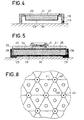
- a soft reflector device can be provided, for example, with a sheet of piezoelectric material 31 placed between electrodes to perform the transducer function on transmission or on reception. This variant is illustrated in FIG. 5.
- the reflector devices described above are particularly well suited to the production of passive listening antennas which include one or more hydrophones.
- the hydrophones are located opposite a reflecting surface composed of a set of devices as described above.
- the shortest distance separating each hydrophone from the reflecting surface is advantageously equal to ⁇ / 4 where ⁇ is the wavelength corresponding to the central frequency of the listening band of the hydrophones.
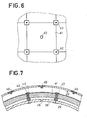
- FIG. 6 illustrates an example of arrangement of the reflectors 41 and hydrophones 40, in a passive listening antenna using a reflective surface of cylindrical shape.
- the reflectors 41 have an elementary reflective surface of square shape and the hydrophones 40 are located directly above the center of symmetry of each elementary surface.
- the reflectors 41 are held contiguously on a base by means of stirrups 42 held by tie rods 43, for example of steel.
- Figure 7 is a sectional view of the device of Figure 6.
- the base 26 of the antenna being for example cylindrical
- the reflectors 41 are curved to match the structure and are held contiguously by means of stirrups 42 retained by steel tie rods 43 on the base 26.
- Holes 45 allow the water to exert hydrostatic pressure on the faces 29 of the reflector devices according to the invention.
- FIG. 8 illustrates an example of an arrangement similar to that of FIG. 6, but where the reflectors 41 are triangular. It is obvious that other arrangements of reflectors and hydrophones can be adopted without departing from the scope of the present invention.
Landscapes
- Physics & Mathematics (AREA)
- Engineering & Computer Science (AREA)
- Acoustics & Sound (AREA)
- Multimedia (AREA)
- Transducers For Ultrasonic Waves (AREA)
- Measurement Of Velocity Or Position Using Acoustic Or Ultrasonic Waves (AREA)
Applications Claiming Priority (2)
| Application Number | Priority Date | Filing Date | Title |
|---|---|---|---|
| FR8300753A FR2539541B1 (fr) | 1983-01-19 | 1983-01-19 | Dispositif a interface reflectrice d'ondes acoustiques |
| FR8300753 | 1983-01-19 |
Publications (3)
| Publication Number | Publication Date |
|---|---|
| EP0114764A2 true EP0114764A2 (de) | 1984-08-01 |
| EP0114764A3 EP0114764A3 (en) | 1984-08-22 |
| EP0114764B1 EP0114764B1 (de) | 1987-09-02 |
Family
ID=9285062
Family Applications (1)
| Application Number | Title | Priority Date | Filing Date |
|---|---|---|---|
| EP19840400076 Expired EP0114764B1 (de) | 1983-01-19 | 1984-01-13 | Vorrichtung zur Reflexion von akustischen Wellen |
Country Status (6)
| Country | Link |
|---|---|
| EP (1) | EP0114764B1 (de) |
| AU (1) | AU2355484A (de) |
| CA (1) | CA1239693A (de) |
| DE (1) | DE3465809D1 (de) |
| ES (1) | ES528948A0 (de) |
| FR (1) | FR2539541B1 (de) |
Cited By (5)
| Publication number | Priority date | Publication date | Assignee | Title |
|---|---|---|---|---|
| GB2204217A (en) * | 1987-05-02 | 1988-11-02 | Gec Avionics | Acoustic reflector |
| EP0435753A1 (de) * | 1989-12-29 | 1991-07-03 | Thomson-Csf | Akustischer Reflektor, geeignet für grosse Eintauchtiefen |
| EP0328931A3 (de) * | 1988-02-18 | 1991-07-31 | The B.F. Goodrich Company | Schallwand mit federnden Röhren |
| EP0506529A1 (de) * | 1991-03-29 | 1992-09-30 | Thomson-Csf | Richtantenne für akustische Niederfrequenzwellen |
| FR2720590A1 (fr) * | 1994-05-31 | 1995-12-01 | Thomson Csf | Antenne acoustique passive absorbante. |
Families Citing this family (1)
| Publication number | Priority date | Publication date | Assignee | Title |
|---|---|---|---|---|
| CN115482805B (zh) * | 2022-08-03 | 2025-10-31 | 中国船舶重工集团公司第七一九研究所 | 一种可调控水下声波反射声场的声学超表面 |
Family Cites Families (4)
| Publication number | Priority date | Publication date | Assignee | Title |
|---|---|---|---|---|
| US2811216A (en) * | 1954-04-28 | 1957-10-29 | Harris Transducer Corp | Acoustic baffle construction |
| US2884084A (en) * | 1954-10-28 | 1959-04-28 | Sussman Harry | Acoustic panel |
| DE1815684A1 (de) * | 1968-12-19 | 1970-06-25 | Krupp Gmbh | Reflektor fuer Wasserschall |
| FR2240813B1 (de) * | 1973-08-16 | 1976-04-30 | France Etat |
-
1983
- 1983-01-19 FR FR8300753A patent/FR2539541B1/fr not_active Expired
-
1984
- 1984-01-13 EP EP19840400076 patent/EP0114764B1/de not_active Expired
- 1984-01-13 DE DE8484400076T patent/DE3465809D1/de not_active Expired
- 1984-01-13 CA CA000445311A patent/CA1239693A/en not_active Expired
- 1984-01-18 AU AU23554/84A patent/AU2355484A/en not_active Abandoned
- 1984-01-18 ES ES528948A patent/ES528948A0/es active Granted
Cited By (10)
| Publication number | Priority date | Publication date | Assignee | Title |
|---|---|---|---|---|
| GB2204217A (en) * | 1987-05-02 | 1988-11-02 | Gec Avionics | Acoustic reflector |
| GB2204217B (en) * | 1987-05-02 | 1990-05-23 | Gec Avionics | Acoustic reflector |
| EP0328931A3 (de) * | 1988-02-18 | 1991-07-31 | The B.F. Goodrich Company | Schallwand mit federnden Röhren |
| EP0435753A1 (de) * | 1989-12-29 | 1991-07-03 | Thomson-Csf | Akustischer Reflektor, geeignet für grosse Eintauchtiefen |
| FR2656720A1 (fr) * | 1989-12-29 | 1991-07-05 | Thomson Csf | Reflecteur d'ondes acoustiques pouvant fonctionner sous une forte immersion. |
| US5099457A (en) * | 1989-12-29 | 1992-03-24 | Thomson-Csf | Acoustic wave reflector capable of working under deep submersion |
| EP0506529A1 (de) * | 1991-03-29 | 1992-09-30 | Thomson-Csf | Richtantenne für akustische Niederfrequenzwellen |
| FR2674717A1 (fr) * | 1991-03-29 | 1992-10-02 | Thomson Csf | Antenne acoustique basse frequence directive. |
| FR2720590A1 (fr) * | 1994-05-31 | 1995-12-01 | Thomson Csf | Antenne acoustique passive absorbante. |
| US5600609A (en) * | 1994-05-31 | 1997-02-04 | Thomson-Csf | Absorbent passive acoustic antenna |
Also Published As
| Publication number | Publication date |
|---|---|
| CA1239693A (en) | 1988-07-26 |
| EP0114764B1 (de) | 1987-09-02 |
| EP0114764A3 (en) | 1984-08-22 |
| FR2539541A1 (fr) | 1984-07-20 |
| FR2539541B1 (fr) | 1986-09-19 |
| ES8503449A1 (es) | 1985-02-16 |
| ES528948A0 (es) | 1985-02-16 |
| AU2355484A (en) | 1984-07-26 |
| DE3465809D1 (en) | 1987-10-08 |
Similar Documents
| Publication | Publication Date | Title |
|---|---|---|
| EP0769988B1 (de) | Akustischer breitbandwandler für mehrere frequenzen | |
| EP0641262B1 (de) | Akustische unterwasserantenne mit flächensensor | |
| EP0032082B1 (de) | Elektroakustischer Wandler mit aktiver Kalotte | |
| FR2571898A1 (fr) | Structure de reflecteur a grille double et son procede de montage | |
| EP0100711A2 (de) | Halbwellenwandler unter Anwendung eines aktiven piezoelektrischen Polymerelements | |
| EP0114764B1 (de) | Vorrichtung zur Reflexion von akustischen Wellen | |
| FR2790903A1 (fr) | Haut-parleur | |
| EP0323305B1 (de) | Rohrförmiger piezo-elektrischer Sensor mit grosser Empfindlichkeit | |
| CH691335A5 (fr) | Appareil susceptible d'être immergé et comprenant un transducteur sonore. | |
| EP3198586B1 (de) | Rundstrahlantenne | |
| CA2916582C (fr) | Transducteur a ultrasons | |
| EP2034376B1 (de) | Armbanduhrgehäuse | |
| WO1993010644A1 (fr) | Membrane d'etancheite pour dispositif acoustique sous-marin | |
| EP3325985A1 (de) | Vorrichtung für elektromagnetische dosimetrie und zugehöriges verfahren | |
| EP0899635B1 (de) | Vorrichtung zur Verwendung unter Wasser und mit einem Schallwandler | |
| FR2730335A1 (fr) | Dispositif anti bruit notamment pour accoustique sous-marine | |
| FR2511571A1 (fr) | Transducteur electroacoustique a condensateur a dielectrique solide polarise | |
| CA2306678A1 (fr) | Hydrophone pour la reception des ondes acoustiques ou sismiques | |
| EP0897176B1 (de) | Unterwasserschallabsorber | |
| FR2664750A1 (fr) | Bireflecteur a grilles. | |
| FR3013176A1 (fr) | Ensemble haut-parleur etanche pour forte profondeur | |
| CH686600B5 (fr) | Pièce d'horlogerie comportant un transducteur électro-acoustique. | |
| FR2697709A1 (fr) | Dispositif d'étanchéité de moteurs électro-acoustiques. | |
| FR2713430A1 (fr) | Procédé d'émission d'ondes acoustiques très basses fréquences à forte puissance, et transducteurs correspondants. | |
| CA2314633A1 (fr) | Hydrophone a faible taux de distorsion |
Legal Events
| Date | Code | Title | Description |
|---|---|---|---|
| PUAI | Public reference made under article 153(3) epc to a published international application that has entered the european phase |
Free format text: ORIGINAL CODE: 0009012 |
|
| PUAL | Search report despatched |
Free format text: ORIGINAL CODE: 0009013 |
|
| AK | Designated contracting states |
Designated state(s): DE GB IT |
|
| AK | Designated contracting states |
Designated state(s): DE GB IT |
|
| 17P | Request for examination filed |
Effective date: 19850118 |
|
| GRAA | (expected) grant |
Free format text: ORIGINAL CODE: 0009210 |
|
| AK | Designated contracting states |
Kind code of ref document: B1 Designated state(s): DE GB IT |
|
| ITF | It: translation for a ep patent filed | ||
| REF | Corresponds to: |
Ref document number: 3465809 Country of ref document: DE Date of ref document: 19871008 |
|
| GBT | Gb: translation of ep patent filed (gb section 77(6)(a)/1977) | ||
| PLBE | No opposition filed within time limit |
Free format text: ORIGINAL CODE: 0009261 |
|
| STAA | Information on the status of an ep patent application or granted ep patent |
Free format text: STATUS: NO OPPOSITION FILED WITHIN TIME LIMIT |
|
| 26N | No opposition filed | ||
| PGFP | Annual fee paid to national office [announced via postgrant information from national office to epo] |
Ref country code: DE Payment date: 19921221 Year of fee payment: 10 |
|
| ITTA | It: last paid annual fee | ||
| PG25 | Lapsed in a contracting state [announced via postgrant information from national office to epo] |
Ref country code: DE Effective date: 19941001 |
|
| PGFP | Annual fee paid to national office [announced via postgrant information from national office to epo] |
Ref country code: GB Payment date: 19941219 Year of fee payment: 12 |
|
| PG25 | Lapsed in a contracting state [announced via postgrant information from national office to epo] |
Ref country code: GB Effective date: 19960113 |
|
| GBPC | Gb: european patent ceased through non-payment of renewal fee |
Effective date: 19960113 |