EP0113523A1 - Temperature controlled ammonia synthesis process - Google Patents
Temperature controlled ammonia synthesis process Download PDFInfo
- Publication number
- EP0113523A1 EP0113523A1 EP83307203A EP83307203A EP0113523A1 EP 0113523 A1 EP0113523 A1 EP 0113523A1 EP 83307203 A EP83307203 A EP 83307203A EP 83307203 A EP83307203 A EP 83307203A EP 0113523 A1 EP0113523 A1 EP 0113523A1
- Authority
- EP
- European Patent Office
- Prior art keywords
- effluent
- temperature
- series
- catalyst bed
- passing
- Prior art date
- Legal status (The legal status is an assumption and is not a legal conclusion. Google has not performed a legal analysis and makes no representation as to the accuracy of the status listed.)
- Withdrawn
Links
- QGZKDVFQNNGYKY-UHFFFAOYSA-N Ammonia Chemical compound N QGZKDVFQNNGYKY-UHFFFAOYSA-N 0.000 title claims abstract description 76
- 238000000034 method Methods 0.000 title claims abstract description 40
- 229910021529 ammonia Inorganic materials 0.000 title claims abstract description 38
- 238000003786 synthesis reaction Methods 0.000 title claims description 25
- 230000015572 biosynthetic process Effects 0.000 title claims description 24
- 239000003054 catalyst Substances 0.000 claims abstract description 46
- 230000002194 synthesizing effect Effects 0.000 claims abstract 2
- 239000007789 gas Substances 0.000 claims description 37
- 238000006243 chemical reaction Methods 0.000 claims description 28
- IJGRMHOSHXDMSA-UHFFFAOYSA-N Atomic nitrogen Chemical compound N#N IJGRMHOSHXDMSA-UHFFFAOYSA-N 0.000 claims description 26
- 239000000203 mixture Substances 0.000 claims description 16
- 229910052757 nitrogen Inorganic materials 0.000 claims description 13
- UFHFLCQGNIYNRP-UHFFFAOYSA-N Hydrogen Chemical compound [H][H] UFHFLCQGNIYNRP-UHFFFAOYSA-N 0.000 claims description 12
- 239000001257 hydrogen Substances 0.000 claims description 12
- 229910052739 hydrogen Inorganic materials 0.000 claims description 12
- 239000012467 final product Substances 0.000 claims description 8
- 238000001816 cooling Methods 0.000 claims description 4
- 230000003247 decreasing effect Effects 0.000 claims 1
- 238000010438 heat treatment Methods 0.000 claims 1
- 230000003197 catalytic effect Effects 0.000 description 10
- XEEYBQQBJWHFJM-UHFFFAOYSA-N Iron Chemical compound [Fe] XEEYBQQBJWHFJM-UHFFFAOYSA-N 0.000 description 8
- XKRFYHLGVUSROY-UHFFFAOYSA-N Argon Chemical compound [Ar] XKRFYHLGVUSROY-UHFFFAOYSA-N 0.000 description 6
- 239000003085 diluting agent Substances 0.000 description 4
- 229910052742 iron Inorganic materials 0.000 description 4
- 229910052786 argon Inorganic materials 0.000 description 3
- UQSXHKLRYXJYBZ-UHFFFAOYSA-N Iron oxide Chemical compound [Fe]=O UQSXHKLRYXJYBZ-UHFFFAOYSA-N 0.000 description 2
- 230000000694 effects Effects 0.000 description 2
- 239000001307 helium Substances 0.000 description 2
- 229910052734 helium Inorganic materials 0.000 description 2
- SWQJXJOGLNCZEY-UHFFFAOYSA-N helium atom Chemical compound [He] SWQJXJOGLNCZEY-UHFFFAOYSA-N 0.000 description 2
- VNWKTOKETHGBQD-UHFFFAOYSA-N methane Chemical compound C VNWKTOKETHGBQD-UHFFFAOYSA-N 0.000 description 2
- 238000011084 recovery Methods 0.000 description 2
- 239000007858 starting material Substances 0.000 description 2
- 238000013459 approach Methods 0.000 description 1
- 238000006555 catalytic reaction Methods 0.000 description 1
- 239000000356 contaminant Substances 0.000 description 1
- 238000010924 continuous production Methods 0.000 description 1
- 230000001276 controlling effect Effects 0.000 description 1
- 239000000112 cooling gas Substances 0.000 description 1
- 230000002401 inhibitory effect Effects 0.000 description 1
- 238000004519 manufacturing process Methods 0.000 description 1
- 230000007246 mechanism Effects 0.000 description 1
- 238000010791 quenching Methods 0.000 description 1
- 230000001105 regulatory effect Effects 0.000 description 1
- 238000006467 substitution reaction Methods 0.000 description 1
- 238000010792 warming Methods 0.000 description 1
Images
Classifications
-
- C—CHEMISTRY; METALLURGY
- C01—INORGANIC CHEMISTRY
- C01C—AMMONIA; CYANOGEN; COMPOUNDS THEREOF
- C01C1/00—Ammonia; Compounds thereof
- C01C1/02—Preparation, purification or separation of ammonia
- C01C1/04—Preparation of ammonia by synthesis in the gas phase
- C01C1/0405—Preparation of ammonia by synthesis in the gas phase from N2 and H2 in presence of a catalyst
-
- Y—GENERAL TAGGING OF NEW TECHNOLOGICAL DEVELOPMENTS; GENERAL TAGGING OF CROSS-SECTIONAL TECHNOLOGIES SPANNING OVER SEVERAL SECTIONS OF THE IPC; TECHNICAL SUBJECTS COVERED BY FORMER USPC CROSS-REFERENCE ART COLLECTIONS [XRACs] AND DIGESTS
- Y02—TECHNOLOGIES OR APPLICATIONS FOR MITIGATION OR ADAPTATION AGAINST CLIMATE CHANGE
- Y02P—CLIMATE CHANGE MITIGATION TECHNOLOGIES IN THE PRODUCTION OR PROCESSING OF GOODS
- Y02P20/00—Technologies relating to chemical industry
- Y02P20/50—Improvements relating to the production of bulk chemicals
- Y02P20/52—Improvements relating to the production of bulk chemicals using catalysts, e.g. selective catalysts
Definitions
- the field of the invention is the synthesis of ammonia in a continuous process whereby a gas mixture. containing an approximately stoichometric ratio of hydrogen and nitrogen is passed over a series of catalyst beds at relatively high pressure and controlled temperatures.
- the invention herein relates to temperature regulation in this process by means of heat exchange effected between portions of the gas mixture itself at various stages of its progress through the process.
- Ammonia production as commercially practiced utilizes the seemingly straightforward reaction between nitrogen and hydrogen in stoichometric amounts: N 2 + 3H 2 ⁇ 2NH 3 .
- the reaction is exothermic; accordingly, the equilibrium is shifted to the right by lower temperatures.
- the temperature must be maintained at an elevated level in order to increase the reaction rate sufficiently to carry out the process in a reasonably short amount of time, even though catalysts are also used to accelerate the rate of the reaction.
- an appropriate balance between thermodynamic and kinetic considerations determine the appropriate temperature range at which the synthesis should be operated.
- Thermodynamic considerations would also millitate that the reaction would be favored by higher pressure, since collisions between gas molecules are required to effect the synthesis.
- the pressure range at which this process is generally carried out is over 100 atmospheres, although it has been disclosed that synthesis procedures are possible with pressures of as low as 20 atmospheres (U.S. Patent 3,957,449).
- Temperature regulation is most often accomplished by a "quench" type ammonia conversion process.
- the synthesis gas containing nitrogen and hydrogen in roughly stoichometric amounts (syngas), preferably with as few diluents as possible, is passed through a catalytic bed of, for example, iron or promoted iron, to produce an effluent which is at a higher temperature than the original mixture due to the exothermic nature of the reaction.
- the effluent contains some percentage of ammonia, representing for example, 10 to .15% total volume.
- the temperature of the emerging gas is ordinarily sufficiently high to be thermodynamically inhibitory to further reaction.
- the invention herein relates to a process for synthesis of ammonia which establishes control of the temperature of the synthesis reaction through a combination of heat exchange between portions of the gas mixture flowing through the system, and high pressure steam generation by cooling effluents from a series of catalyst beds.
- syngas or “synthesis gas” refers to a mixture of nitrogen and hydrogen in a ratio of 1:3 approximately, which may contain diluents such as argon. and methane. While it is desirable to have zero diluent concentration, this is seldom achieved, and the syngas though composed substantially of hydrogen and nitrogen in stoichometric ratio may be debilitated proportionally to the amount of contaminants therein.
- the process of the invention is affected by the presence of such diluents in essentially the same manner as alternate methods for carrying out the synthesis would be so affected.
- Fluid product effluent represents the gas which has passed through the entire system and which is to be subjected to recovery processes to extract the ammonia therefrom.
- Catalysts which are successful in accelerating the synthesis of ammonia are well known in the art. Prominent among these are finely.divided iron, and promoted iron catalyst.
- the first catalytic pass results in a conversion of from 15 to 20% of the starting materials to ammonia, and succeeding passes result in further conversions.
- the final product effluent should contain approximately 20% ammonia by volume which represents approximately 30-35% conversion of the starting material.
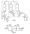
- Syngas as purified as is possible, enters the system at 102 and is passed through a heat exchanger 104 in which the heat source is at least a portion of the final product effluent.
- the syngas which has thus been heated, preferably to a temperature of approximately 500 to 600° F is then divided using the bypass control line with valve at 106, so that a portion of it passes directly finally to the first of the catalytic beds (A) at 108, and another . portion passes through the heat exchanger 110 where it is used to cool the effluent from the first catalytic converter, and resulting in its temperature being further raised.
- the effluent from the heat exchanger l10 is then combined at 112 with the syngas from the bypass and the mixture is fed into the first converter in the series at 108.
- the temperature of the combined gases as they enter the first converter, labeled A in Figure 1, is preferably between 700 and 800° F.
- a portion of the nitrogen and hydrogen are converted to ammonia in an exothermic reaction such that the exit temperature at 114 is between 900 and 1000° F.
- the effluuent is cooled by providing the heat to the feed syngas in the aforesaid heat exchanger 110.
- Control over the final temperature before entry into catalyst bed B is maintained by the bypass line controlled by valve 106 which controls the amount of cooling gas.
- the gas entering the second catalytic bed B at 122 is preferably between 700 and 800° F. Further conversion to ammonia takes place in converter B with generation of sufficient heat to provide an effluent with an exit temperature at 124 of 850 to 950° F.
- This effluent gas is cooled by operation of a high pressure steam generator 126 to a temperature of 700 to 800° F, the proper temperature for the pass over the catalyst bed in converter C. Control over this process is maintained by a control valve in the bypass line at 127; the fraction of gas bypassing the steam generator being-sufficient to retain the proper high temperature. Similarly, the reaction taking place in converter C results in an increase in temperature of the flowing gas mixture so that the temperature of the gas at the high pressure steam generator 128 is 800 to 900°F. As a result of the operation of the high pressure steam generator 128, the gas is cooled to 600 to 750° F. Again, a bypass and control valve, 129, are provided.
- At least a portion of the gas emerging from the high pressure steam generator 128 is passed through the heat exchanger 104 to heat the original feed syngas to a temperature of about 500 to 600°F.
- the final product effluent is then subjected, by conventional means, to an ammonia recovery process.
- control mechanisms to regulate the temperature by controlling gas flow previous to the first heat exchanger (106) and in parallel with the high pressure steam generators (127 and 129).
- the invention is not limited to these locations for regulatory opportunities.
- a bypass with control valve could be provided subsequent to the high pressure steam generator 128 so as to control the amount of warming gas entering the heat exchanger 104.
- a bypass could be provided after the effluent from tank A so that only a portion of the heated gas would enter the heat exchanger 110.
- bypass may be by means of a separate bypass line with control valve.
- .an internal bypass valve as shown schematically in Figure 2
- the incoming gas through inlet 201 exits through outlet 202 when the control valve 205 is closed so as to prevent flow of gas through passage 206. Varying proportions of the gas are allowed to exit at outlet 204 depending on the adjustment-of the opening of this control .. valve.
- Bypass valves of this general instruction are well known in the art, and provide additional economy by eliminating the need for an extra line.
- the catalyst is a 15m 3 cylindrical bed of 2.48m ID and 3.lm in length (iron oxide).
- the exit gas from A is at 964 °F and contains 2,549 kg moles of ammonia, per hour 15,505 kg moles of hydrogen and 5,085 moles of nitrogen, representing a total of approximately 20% conversion.
- the exit gas is then passed through heat exchanger 110 to attain a temperature of 752 °F, whereupon it enters catalyst bed B.
- the catalyst bed in B is 46m3 and is also cylindrical of 3.0m ID and 6.6m in length.
- the exit gas from the catalyst B is at 401 °F, and contains 3,740 moles ammonia, 13,720 moles hydrogen and 4,490 moles nitrogen, representing a total conversion of 29%.
- the effluent from the high pressure steam generator when combined with the gas which has circulated through.the bypass valve system at 129 is at 752 °F as it enters the third catalyst bed in the series, C.
- the catalyst bed at C is 77m 3 and has a 3.2m ID and is 9.6m long.
- the effluent contains 4510 kg moles ammonia per hour, 12,564 kg moles hydrogen and 4105 kg moles nitrogen, representing 35% total conversion.
- the temperature of existing mixture, which is 849 °F is then lowered to 619° F by generation of steam before further cooling in the heat exchanger 104.
- the final product effluent exiting at 132 then represents approximately 31% conversion to ammonia (based on nitrogen fed to the system), and has an exit temperature of 181 °F.
- ID means "internal diameter".
Landscapes
- Chemical & Material Sciences (AREA)
- Organic Chemistry (AREA)
- Chemical Kinetics & Catalysis (AREA)
- Analytical Chemistry (AREA)
- Inorganic Chemistry (AREA)
- Catalysts (AREA)
- Physical Or Chemical Processes And Apparatus (AREA)
- Organic Low-Molecular-Weight Compounds And Preparation Thereof (AREA)
- Devices And Processes Conducted In The Presence Of Fluids And Solid Particles (AREA)
Applications Claiming Priority (2)
| Application Number | Priority Date | Filing Date | Title |
|---|---|---|---|
| US06/444,720 US4510123A (en) | 1982-11-26 | 1982-11-26 | Temperature controlled ammonia synthesis process |
| US444720 | 1982-11-26 |
Publications (1)
| Publication Number | Publication Date |
|---|---|
| EP0113523A1 true EP0113523A1 (en) | 1984-07-18 |
Family
ID=23766062
Family Applications (1)
| Application Number | Title | Priority Date | Filing Date |
|---|---|---|---|
| EP83307203A Withdrawn EP0113523A1 (en) | 1982-11-26 | 1983-11-25 | Temperature controlled ammonia synthesis process |
Country Status (7)
| Country | Link |
|---|---|
| US (1) | US4510123A (en)) |
| EP (1) | EP0113523A1 (en)) |
| JP (1) | JPS59102815A (en)) |
| AU (1) | AU568823B2 (en)) |
| GB (1) | GB2144724B (en)) |
| IN (1) | IN161243B (en)) |
| NO (1) | NO834310L (en)) |
Cited By (2)
| Publication number | Priority date | Publication date | Assignee | Title |
|---|---|---|---|---|
| EP0217929A4 (en) * | 1985-04-08 | 1988-02-03 | Santa Fe Braun Inc | AMMONIA SYNTHESIS PROCESS WITH TEMPERATURE REGULATION. |
| EP0179392A3 (en) * | 1984-10-16 | 1989-01-04 | The M. W. Kellogg Company | Ammonia synthesis process |
Families Citing this family (10)
| Publication number | Priority date | Publication date | Assignee | Title |
|---|---|---|---|---|
| CA1229467A (en) * | 1983-11-10 | 1987-11-24 | Exxon Research And Engineering Company | Low severity hydrocarbon steam reforming process |
| SU1696387A1 (ru) * | 1986-10-17 | 1991-12-07 | Институт катализа СО АН СССР | Способ синтеза аммиака |
| US4867959A (en) * | 1986-11-20 | 1989-09-19 | Santa Fe Braun, Inc. | Process for synthesizing ammonia |
| US4744966A (en) * | 1986-11-20 | 1988-05-17 | Santa Fe Braun Inc. | Process for synthesizing ammonia |
| US5236671A (en) * | 1990-09-24 | 1993-08-17 | C. F. Braun, Inc. | Apparatus for ammonia synthesis |
| US5840933A (en) * | 1996-10-29 | 1998-11-24 | Arco Chemical Technology, L.P. | Catalytic converter system and progress |
| DK173023B1 (da) * | 1997-04-21 | 1999-11-15 | Topsoe Haldor As | Fremgangsmåde og reaktor til fremstilling af ammoniak |
| DE10116150A1 (de) * | 2001-03-31 | 2002-10-10 | Mg Technologies Ag | Verfahren zum katalytischen Erzeugen von Ammoniak aus Synthesegas |
| WO2014144788A1 (en) * | 2013-03-15 | 2014-09-18 | Dole Food Company, Inc. | Process for ripening bananas inside of a shipping container |
| CN112499646B (zh) * | 2020-11-19 | 2024-04-05 | 宁夏坤辉气化有限公司 | 一种串联式氨合成工艺 |
Citations (6)
| Publication number | Priority date | Publication date | Assignee | Title |
|---|---|---|---|---|
| AT171152B (de) * | 1949-02-24 | 1952-05-10 | Montedison Spa | Verfahren und Vorrichtung zur Durchführung der katalytischen Hochdrucksynthese, insbesondere von Ammoniak oder Methanol |
| US3395982A (en) * | 1966-10-14 | 1968-08-06 | United States Steel Corp | Synthetic production of ammonia |
| DE1442750A1 (de) * | 1963-03-26 | 1968-11-21 | Kralovopolska Strojirna Zd Y C | Verfahren und Vorrichtung zur Regelung der Betriebstemperaturen von exothermen Hochdruckreaktionen |
| US3851046A (en) * | 1971-02-08 | 1974-11-26 | Braun Co C | Ammonia synthesis process |
| US3957449A (en) * | 1972-02-28 | 1976-05-18 | Imperial Chemical Industries Limited | Synthesis plant |
| US4230680A (en) * | 1978-07-17 | 1980-10-28 | Pullman Incorporated | Low energy process for synthesis of ammonia |
Family Cites Families (2)
| Publication number | Priority date | Publication date | Assignee | Title |
|---|---|---|---|---|
| EP0001329B1 (en) * | 1977-09-16 | 1981-05-20 | Imperial Chemical Industries Plc | Process and plant for producing ammonia |
| DE2967342D1 (en) * | 1978-07-17 | 1985-02-14 | Kellogg M W Co | Synthesis of ammonia and converter system therefor |
-
1982
- 1982-11-26 US US06/444,720 patent/US4510123A/en not_active Expired - Fee Related
-
1983
- 1983-09-23 IN IN1167/CAL/83A patent/IN161243B/en unknown
- 1983-11-15 AU AU21381/83A patent/AU568823B2/en not_active Ceased
- 1983-11-18 JP JP58217645A patent/JPS59102815A/ja active Pending
- 1983-11-24 NO NO834310A patent/NO834310L/no unknown
- 1983-11-25 EP EP83307203A patent/EP0113523A1/en not_active Withdrawn
- 1983-11-25 GB GB08331506A patent/GB2144724B/en not_active Expired
Patent Citations (6)
| Publication number | Priority date | Publication date | Assignee | Title |
|---|---|---|---|---|
| AT171152B (de) * | 1949-02-24 | 1952-05-10 | Montedison Spa | Verfahren und Vorrichtung zur Durchführung der katalytischen Hochdrucksynthese, insbesondere von Ammoniak oder Methanol |
| DE1442750A1 (de) * | 1963-03-26 | 1968-11-21 | Kralovopolska Strojirna Zd Y C | Verfahren und Vorrichtung zur Regelung der Betriebstemperaturen von exothermen Hochdruckreaktionen |
| US3395982A (en) * | 1966-10-14 | 1968-08-06 | United States Steel Corp | Synthetic production of ammonia |
| US3851046A (en) * | 1971-02-08 | 1974-11-26 | Braun Co C | Ammonia synthesis process |
| US3957449A (en) * | 1972-02-28 | 1976-05-18 | Imperial Chemical Industries Limited | Synthesis plant |
| US4230680A (en) * | 1978-07-17 | 1980-10-28 | Pullman Incorporated | Low energy process for synthesis of ammonia |
Cited By (2)
| Publication number | Priority date | Publication date | Assignee | Title |
|---|---|---|---|---|
| EP0179392A3 (en) * | 1984-10-16 | 1989-01-04 | The M. W. Kellogg Company | Ammonia synthesis process |
| EP0217929A4 (en) * | 1985-04-08 | 1988-02-03 | Santa Fe Braun Inc | AMMONIA SYNTHESIS PROCESS WITH TEMPERATURE REGULATION. |
Also Published As
| Publication number | Publication date |
|---|---|
| GB2144724B (en) | 1987-05-13 |
| IN161243B (en)) | 1987-10-31 |
| AU568823B2 (en) | 1988-01-14 |
| GB8331506D0 (en) | 1984-01-04 |
| GB2144724A (en) | 1985-03-13 |
| US4510123A (en) | 1985-04-09 |
| NO834310L (no) | 1984-05-28 |
| JPS59102815A (ja) | 1984-06-14 |
| AU2138183A (en) | 1984-05-31 |
Similar Documents
| Publication | Publication Date | Title |
|---|---|---|
| EP0268469B1 (en) | Improved process for synthesizing ammonia | |
| US4510123A (en) | Temperature controlled ammonia synthesis process | |
| WO2013097958A1 (en) | Adiabatic multi-bed catalytic converter with inter-bed cooling and a related process | |
| TWI506004B (zh) | 自合成氣體產生富含甲烷之氣體之方法及設備 | |
| JP4545855B2 (ja) | 合成ガスからメタノール/ジメチルエーテル混合物を合成する方法 | |
| US3967936A (en) | Methanation process utilizing split cold gas recycle | |
| US4161393A (en) | Shift conversion of raw gas from gasification of coal | |
| RU2338685C2 (ru) | Способ получения синтез-газа и устройство для его осуществления | |
| US4744966A (en) | Process for synthesizing ammonia | |
| US4624842A (en) | Temperature controlled ammonia synthesis process | |
| EP0550525B1 (en) | High conversion ammonia synthesis | |
| CA2568297A1 (en) | Method for carrying out heterogeneous catalytic exothermic gas phase reactions | |
| JP4093632B2 (ja) | アンモニアを製造する方法および装置 | |
| US4212817A (en) | Control of highly exothermic chemical reactions | |
| EP0550539A1 (en) | AMMONIA GAS SYNTHESIS APPARATUS. | |
| US4230680A (en) | Low energy process for synthesis of ammonia | |
| RU2152378C1 (ru) | Способ получения метанола | |
| EP0492544B1 (en) | Process for the preparation of ammonia synthesis gas | |
| US1704214A (en) | Synthetic production of bodies from their component gases | |
| US12139404B2 (en) | Method and device for carrying out a water-gas shift reactor | |
| RU2198838C1 (ru) | Способ получения метанола | |
| JPS63159210A (ja) | 炭酸ガスの分解方法 | |
| EP0049892B1 (en) | Process for the production of gasoline | |
| WO2024180084A1 (en) | System for integrated nitric acid and ammonia production and method of production thereof | |
| MXPA98002989A (en) | Process and reactor for ammoni preparation |
Legal Events
| Date | Code | Title | Description |
|---|---|---|---|
| PUAI | Public reference made under article 153(3) epc to a published international application that has entered the european phase |
Free format text: ORIGINAL CODE: 0009012 |
|
| AK | Designated contracting states |
Designated state(s): AT BE CH DE FR IT LI LU NL SE |
|
| 17P | Request for examination filed |
Effective date: 19850114 |
|
| RAP1 | Party data changed (applicant data changed or rights of an application transferred) |
Owner name: SANTA FE BRAUN INC. |
|
| 17Q | First examination report despatched |
Effective date: 19881020 |
|
| STAA | Information on the status of an ep patent application or granted ep patent |
Free format text: STATUS: THE APPLICATION IS DEEMED TO BE WITHDRAWN |
|
| 18D | Application deemed to be withdrawn |
Effective date: 19890701 |
|
| RIN1 | Information on inventor provided before grant (corrected) |
Inventor name: GROTZ, BERNARD JOHN, JR. |