EP0113399B1 - Gas- und flüssigkeitsdichte Abdichtung des metallischen Poles eines Akkumulators - Google Patents
Gas- und flüssigkeitsdichte Abdichtung des metallischen Poles eines Akkumulators Download PDFInfo
- Publication number
- EP0113399B1 EP0113399B1 EP83110357A EP83110357A EP0113399B1 EP 0113399 B1 EP0113399 B1 EP 0113399B1 EP 83110357 A EP83110357 A EP 83110357A EP 83110357 A EP83110357 A EP 83110357A EP 0113399 B1 EP0113399 B1 EP 0113399B1
- Authority
- EP
- European Patent Office
- Prior art keywords
- pole
- trough
- ring
- sealing assembly
- casting compound
- Prior art date
- Legal status (The legal status is an assumption and is not a legal conclusion. Google has not performed a legal analysis and makes no representation as to the accuracy of the status listed.)
- Expired
Links
- 238000007789 sealing Methods 0.000 title claims abstract description 20
- 239000007788 liquid Substances 0.000 title claims abstract 5
- 239000004033 plastic Substances 0.000 claims abstract description 17
- 229920003023 plastic Polymers 0.000 claims abstract description 17
- 150000001875 compounds Chemical class 0.000 claims abstract description 8
- 239000003822 epoxy resin Substances 0.000 claims abstract description 6
- 229920000647 polyepoxide Polymers 0.000 claims abstract description 6
- 239000002253 acid Substances 0.000 claims abstract description 5
- 238000010125 resin casting Methods 0.000 claims abstract 3
- 238000005266 casting Methods 0.000 claims description 9
- 229920001577 copolymer Polymers 0.000 claims description 2
- 229920002994 synthetic fiber Polymers 0.000 claims 3
- 239000000853 adhesive Substances 0.000 claims 1
- 230000001070 adhesive effect Effects 0.000 claims 1
- 230000002093 peripheral effect Effects 0.000 claims 1
- 239000000463 material Substances 0.000 description 5
- -1 permanently elastic Substances 0.000 description 3
- QAOWNCQODCNURD-UHFFFAOYSA-N Sulfuric acid Chemical compound OS(O)(=O)=O QAOWNCQODCNURD-UHFFFAOYSA-N 0.000 description 2
- 238000010276 construction Methods 0.000 description 2
- 238000011161 development Methods 0.000 description 2
- 230000018109 developmental process Effects 0.000 description 2
- 239000003792 electrolyte Substances 0.000 description 2
- 238000000034 method Methods 0.000 description 2
- 238000004382 potting Methods 0.000 description 2
- 239000003566 sealing material Substances 0.000 description 2
- 238000003466 welding Methods 0.000 description 2
- 239000004698 Polyethylene Substances 0.000 description 1
- 239000004743 Polypropylene Substances 0.000 description 1
- 238000006073 displacement reaction Methods 0.000 description 1
- 238000005538 encapsulation Methods 0.000 description 1
- 238000004519 manufacturing process Methods 0.000 description 1
- 239000002184 metal Substances 0.000 description 1
- 229920000573 polyethylene Polymers 0.000 description 1
- 229920001155 polypropylene Polymers 0.000 description 1
- 239000012858 resilient material Substances 0.000 description 1
- 239000000565 sealant Substances 0.000 description 1
- 229920001169 thermoplastic Polymers 0.000 description 1
- 239000004416 thermosoftening plastic Substances 0.000 description 1
Images
Classifications
-
- H—ELECTRICITY
- H01—ELECTRIC ELEMENTS
- H01M—PROCESSES OR MEANS, e.g. BATTERIES, FOR THE DIRECT CONVERSION OF CHEMICAL ENERGY INTO ELECTRICAL ENERGY
- H01M50/00—Constructional details or processes of manufacture of the non-active parts of electrochemical cells other than fuel cells, e.g. hybrid cells
- H01M50/10—Primary casings; Jackets or wrappings
- H01M50/183—Sealing members
- H01M50/184—Sealing members characterised by their shape or structure
-
- H—ELECTRICITY
- H01—ELECTRIC ELEMENTS
- H01M—PROCESSES OR MEANS, e.g. BATTERIES, FOR THE DIRECT CONVERSION OF CHEMICAL ENERGY INTO ELECTRICAL ENERGY
- H01M50/00—Constructional details or processes of manufacture of the non-active parts of electrochemical cells other than fuel cells, e.g. hybrid cells
- H01M50/10—Primary casings; Jackets or wrappings
- H01M50/172—Arrangements of electric connectors penetrating the casing
-
- H—ELECTRICITY
- H01—ELECTRIC ELEMENTS
- H01M—PROCESSES OR MEANS, e.g. BATTERIES, FOR THE DIRECT CONVERSION OF CHEMICAL ENERGY INTO ELECTRICAL ENERGY
- H01M50/00—Constructional details or processes of manufacture of the non-active parts of electrochemical cells other than fuel cells, e.g. hybrid cells
- H01M50/10—Primary casings; Jackets or wrappings
- H01M50/183—Sealing members
- H01M50/186—Sealing members characterised by the disposition of the sealing members
- H01M50/188—Sealing members characterised by the disposition of the sealing members the sealing members being arranged between the lid and terminal
-
- H—ELECTRICITY
- H01—ELECTRIC ELEMENTS
- H01M—PROCESSES OR MEANS, e.g. BATTERIES, FOR THE DIRECT CONVERSION OF CHEMICAL ENERGY INTO ELECTRICAL ENERGY
- H01M50/00—Constructional details or processes of manufacture of the non-active parts of electrochemical cells other than fuel cells, e.g. hybrid cells
- H01M50/10—Primary casings; Jackets or wrappings
- H01M50/183—Sealing members
- H01M50/19—Sealing members characterised by the material
- H01M50/193—Organic material
-
- Y—GENERAL TAGGING OF NEW TECHNOLOGICAL DEVELOPMENTS; GENERAL TAGGING OF CROSS-SECTIONAL TECHNOLOGIES SPANNING OVER SEVERAL SECTIONS OF THE IPC; TECHNICAL SUBJECTS COVERED BY FORMER USPC CROSS-REFERENCE ART COLLECTIONS [XRACs] AND DIGESTS
- Y02—TECHNOLOGIES OR APPLICATIONS FOR MITIGATION OR ADAPTATION AGAINST CLIMATE CHANGE
- Y02E—REDUCTION OF GREENHOUSE GAS [GHG] EMISSIONS, RELATED TO ENERGY GENERATION, TRANSMISSION OR DISTRIBUTION
- Y02E60/00—Enabling technologies; Technologies with a potential or indirect contribution to GHG emissions mitigation
- Y02E60/10—Energy storage using batteries
Definitions
- the invention relates to a gas and liquid-tight seal of the metallic pole of an accumulator according to the preamble of claim 1.
- DE-A-3 037143 discloses a seal of the type described at the outset, a cylindrical insert ring in the form of a metal sleeve being welded to the upper outer circumference of the pole.
- An annular cavity is provided in the direction of the housing interior in this insert ring towards the pole.
- This cavity like the lower end of the insert ring and the entire outer diameter of the same, is surrounded by a sealing material made of elastic, resilient material and firmly connected to it. The sealing material should achieve a movable seal against the inner circumference of the pole trough.
- a 0-shaped sealing ring between the housing passage opening and a plastic jacket is known, which is rigidly connected to the circumference of the lead pole.
- a pole seal between a pole trough and the lead pole is known, several layers being provided one above the other, namely a lower layer made of hard casting, an adjoining middle layer made of thermoplastic, permanently elastic, acid-resistant plastic, and one thereon adjacent top layer made of hard casting.
- the invention has for its object to form a seal according to the preamble of claim 1 so that the disadvantages of the prior art are avoided and the seal between the pole and plastic cover is improved while avoiding a metallic pole socket.
- the basic idea of the invention consists in an insert ring between a pole trough inside the plastic cover and the metallic pole passed through the bottom of the pole trough, the inside of the insert ring being rigidly and gas-tightly connected to the pole surface and the outer surface of the insert ring slidingly with the inner surface of the pole trough seals.
- the inner seal expediently consists of a highly viscous 2-component casting, which is commercially available from Ciba-Geigy AG, Basel, under the designation XW 463 A.
- the outer seal preferably consists of three O-rings, which are guided in guide grooves on the outer surface of the insert ring under prestress and press against the inner surface of the pole trough.
- a plastic should be selected as the material for the insert ring, which has the best possible adhesion with the casting compound used.
- polyethylene or polypropylene are not suitable, materials from which the cell housing usually consists, but ABS or acrylic-butadiene-styrene copolymer, which is available, for example, from the German company BASF under the name Luran.
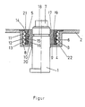
- the figure shown shows a cross section through a plastic cover together with the seal and the pole.
- the pole is denoted by 1, the plastic cover by 2 and the pole trough which is formed in one piece with the plastic cover 2 and extends into the interior of the accumulator by 3.
- the pole 1 is guided outwards through the base 4.
- the sealing of the pole 1 with respect to the pole trough 3 is effected by an insert ring 10 which divides an inner space 9 and an outer space 22 with approximately the same thickness.
- the inner divided ring is filled with a two-component epoxy resin encapsulation 17, which also extends into an annular groove 18 of the pole 1 and, on the other hand, is guided around a radially inwardly projecting annular rib 19 of the insert part 10.
- the outer sealing of the insert part 10 with respect to the inner surface 8 of the pole trough 3 is effected by three O-rings 11, 12, 13 arranged one below the other, which are guided in corresponding annular grooves 14, 15, 16 on the outer surface 6 of the insert ring 10.
- Sealing ring 20 preferably made of acid-resistant rubber, which is intended to provide an additional seal for the epoxy resin potting, but should facilitate the sliding of the pole 1.
- the upper edge of the insert part 10 has a radially outwardly extending flat outer edge 21 which fits into corresponding (not designated) annular recesses in the plastic cover 2 such that the outer surface of the insert ring 10 and the surface of the plastic cover 2 form a plane.
Landscapes
- Chemical & Material Sciences (AREA)
- Chemical Kinetics & Catalysis (AREA)
- Electrochemistry (AREA)
- General Chemical & Material Sciences (AREA)
- Sealing Battery Cases Or Jackets (AREA)
- Connection Of Batteries Or Terminals (AREA)
- Gasket Seals (AREA)
- Sealing Devices (AREA)
- Supply Devices, Intensifiers, Converters, And Telemotors (AREA)
- Feeding, Discharge, Calcimining, Fusing, And Gas-Generation Devices (AREA)
Description
- Gas- und flüssigkeitsdichte Abdichtung des metallischen Poles eines Akkumulators. Die Erfindung bezieht sich auf eine gas- und flüssigkeitsdichter Abdichtung des metallischen Poles eines Akkumulators gemäß dem Oberbegriff des Anspruches 1.
- Trotz einer großen Anzahl von Entwicklungen ist es noch nicht gelungen, eine Polabdichtung zu realisieren, welche unter allen Einsatzbedingungen gleich zuverlässig arbeitet und bei der der Aufwand in vernünftigen Grenzen bleibt. Insbesondere ist dem Umstand Rechnung zu tragen, daß die Elektrodenplatten unter bestimmten Betriebsbedingungen und fortgeschrittener Lebensdauer an Höhe zunehmen, was als Plattenwachstum bezeichnet wird. Ein weiteres Problem besteht darin, daß der Elektrolyt, im allgemeinen ein schwefelsäure-haltiger Elektrolyt, gegen viele Abdichtungsmittel sehr aggressiv ist. Um eine gleitende Abdichtung zum Pol hin selbst zu bewirken, wäre eine aufwendige mechanische Nachbehandlung des Poles erforderlich, um eine exakte Gleitfläche, etwa für O-Ringe, zu bilden.
- Um dies zu vermeiden, wurde unter anderem vorgeschlagen, eine den Pol umgebende metallische Polbuchse am oberen Ende mit diesem zu verschweißen und die Außenfläche dieser entsprechend glatten Polbuchse gegen die Innenfläche einer Polwanne, die einstückig mit dem Kunststoffdeckel ausgebildet ist, abzudichten.
- Das Verschweißen der Polbuchse mit dem Pol ergibt keine genaue Achsparallelität zwischen Pol und Polbuchse. Aus diesem Grunde ergeben sich erhebliche Abdichtungsprobleme der Außenfläche der Polbuchse mit der Innenfläche der Polwanne. Abgesehen davon ist das dafür verwendbare Material, im Falle von Bleiakkumulatoren Blei, schwer und teuer. Darüberhinaus ist der erforderliche Schweißvorgang aufwendig.
- Aus der DE-A-3 037143 ist eine Abdichtung der eingangs geschilderten Art bekannt, wobei ein zylindrischer Einsatzring in Form einer Metallhülse mit dem oberen Außenumfang des Poles verschweißt ist. In Richtung Gehäuseinneres ist bei diesem Einsatzring zum Pol hin ein ringförmiger Hohlraum vorgesehen. Dieser Hohlraum ist wie das untere Ende des Einsatzringes und der gesamte Außendurchmesser desselben mit einem Dichtungsmaterial aus elastischem, federndem Material umgeben und mit diesem fest verbunden. Das Dichtmaterial soll gegen den Innenumfang der Polwanne eine bewegliche Abdichtung erreichen.
- Aus der DE-A-2 757 568, Figur 2, ist ein 0- förmiger Abdichtungsring zwischen Gehäusedurchtrittsöffnung und einer Kunststoffummantelung bekannt, die mit dem Umfang des Bleipoles starr verbunden ist. Aus der DE-A-3 035 842 ist eine Polabdichtung zwischen einer Polwanne und dem Bleipol bekannt, wobei übereinander mehrere Schichten vorgesehen sind, nämlich eine untere Schicht aus Hartverguß, eine daran angrenzende mittlere Schicht aus thermoplastischem, dauerelastischem, säurebeständigem Kunststoff, und eine daran angrenzende obere Schicht aus Hartverguß.
- Sämtliche Abdichtungen weisen Nachteile auf, wie eingangs geschildert. Der Erfindung liegt die Aufgabe zugrunde, eine Abdichtung gemäß dem Oberbegriff des Anspruches 1 so auszubilden, daß die angeführten Nachteile des Standes der Technik vermieden werden und die Abdichtung zwischen Pol und Kunststoffdeckel bei Vermeidung einer metallischen Polbuchse verbessert wird.
- Die Aufgabe wird erfindungsgemäß durch die Merkmale des Kennzeichens des Anspruches 1 gelöst. Weitere Ausbildungen der Erfindung sind in den Unteransprüchen dargestellt.
- Die Grundidee der Erfindung besteht in einem Einsatzring zwischen einer Polwanne innerhalb der Kunststoffdeckels und dem durch den Boden der Polwanne hindurchgeführten metallischen Pol, wobei die Innenseite des Einsatzringes starr und gasdicht mit der Poloberfläche verbunden ist und wobei die Außenfläche des Einsatzringes gleitend mit der Innenfläche der Polwanne abdichtet.
- Zweckmäßigerweise besteht die innere Abdichtung aus einem hochviskosen 2-Komponenten-Verguß, der von der Firma Ciba-Geigy AG, Basel, unter der Bezeichnung XW 463 A im Handel ist. Die äußere Abdichtung besteht aus vorzugsweise drei O-Ringen, die in Führungsnuten der Außenfläche des Einsatzringes unter Vorspannung geführt sind und an die Innenfläche der Polwanne drücken. Als Material für den Einsatzring soll ein Kunststoff gewählt werden, der eine möglichst gute Haftung mit der verwendeten Vergußmasse aufweist. Dazu eignen sich beispielsweise nicht Polyäthylen oder Polypropylen, Materialien, aus denen üblicherweise das Zellengehäuse besteht, jedoch ABS- oder Acryl-Butadien-Styrol-Kopolymerisat, das beispielsweise von der deutschen Firma BASF unter dem Namen Luran erhältlich ist.
- Es zeigte sich, daß die genannte Konstruktion zu einer sehr guten Abdichtung, auch bei längerem Betrieb und den unterschiedlichsten Einsatzbedingungen führt, wobei die erforderliche axiale Bewegungsfreiheit für den Bleipol besteht. Darüberhinaus bestehen gegenüber anderen bekannten Verfahren folgende Vorteile :
- besonders einfacher Aufbau und einfache Herstellung, da nur ein einziger Verguß erforderlich ist,
- eine genaue Einhaltung der Schichthöhen verschiedener Schichten, wie bei einer Mehrfach-Verguß-Polabdichtung entfällt,
- ein Plattenwachstum und als Folge davon eine Verschiebung des Poles nach außen beeinträchtigt wegen der beweglichen O-Ring-Abdichtung nicht die Dichtungsqualität,
- der Aufbau der Abdichtung ist völlig unabhängig vom verwendeten Kasten-material,
- eine mechanische Bearbeitung der Poloberfläche entfällt.
- Ein Ausführungsbeispiel der Erfindung ist in der einzigen Figur dargestellt.
- Die dargestellte Figur zeigt einen Querschnitt durch einen Kunststoffdeckel nebst Abdichtung und durchgeführtem Pol.
- In der Figur ist der Pol mit 1, der Kunststoffdeckel mit 2 und die einstückig mit dem Kunststoffdeckel 2 ausgebildete, sich ins Akkumulatorinnere erstreckende Polwanne mit 3 bezeichnet. In der Mitte der Polwanne 3 ist der Pol 1 durch den Boden 4 hindurch nach außen geführt.
- Die Abdichtung des Poles 1 gegenüber der Polwanne 3 wird durch einen Einsatzring 10 bewirkt, der einen inneren Raum 9 und einen äußeren Raum 22 mit etwa gleicher Dicke abteilt. Der innere abgeteilte Ring ist durch einen 2-Komponenten-Epoxidharzverguß 17 ausgefüllt, der sich im übrigen auch in eine Ringnut 18 des Poles 1 erstreckt und andererseits um eine radial nach innen ragende Ringrippe 19 des Einsatzteiles 10 herumgeführt ist.
- Die Außenabdichtung des Einsatzteiles 10 gegenüber der Innenfläche 8 der Polwanne 3 wird durch drei untereinander angeordnete O-Ringe 11, 12, 13 bewirkt, welche in entsprechenden Ringnuten 14, 15, 16 an der Außenfläche 6 des Einsatzringes 10 geführt sind.
- An der Durchtrittsstelle des Poles 1 in der zentralen Öffnung des Bodens 4 ist ein. Abdichtring 20, vorzugsweise aus säurebeständigem Gummi, angebracht, der eine zusätzliche Abdichtung für den Epoxidharzverguß darstellen soll, jedoch das Gleiten des Poles 1 erleichtern soll. Der obere Rand des Einsatzteiles 10 weist einen radial nach außen sich erstreckenden ebenen Außenrand 21 auf, der in entsprechenden (nicht bezeichneten) ringförmigen Aussparungen des kunststoffdeckels 2 derart hineinpaßt, daß Außenfläche des Einsatzringes 10 und Oberfläche des Kunststoffdeckels 2 eine Ebene bilden.
Claims (8)
Priority Applications (1)
| Application Number | Priority Date | Filing Date | Title |
|---|---|---|---|
| AT83110357T ATE26193T1 (de) | 1982-12-15 | 1983-10-18 | Gas- und fluessigkeitsdichte abdichtung des metallischen poles eines akkumulators. |
Applications Claiming Priority (2)
| Application Number | Priority Date | Filing Date | Title |
|---|---|---|---|
| DE8235188U | 1982-12-15 | ||
| DE19828235188U DE8235188U1 (de) | 1982-12-15 | 1982-12-15 | Gas- und fluessigkeitsdichte abdichtung des metallischen poles eines akkumulators |
Publications (2)
| Publication Number | Publication Date |
|---|---|
| EP0113399A1 EP0113399A1 (de) | 1984-07-18 |
| EP0113399B1 true EP0113399B1 (de) | 1987-03-25 |
Family
ID=6746516
Family Applications (1)
| Application Number | Title | Priority Date | Filing Date |
|---|---|---|---|
| EP83110357A Expired EP0113399B1 (de) | 1982-12-15 | 1983-10-18 | Gas- und flüssigkeitsdichte Abdichtung des metallischen Poles eines Akkumulators |
Country Status (4)
| Country | Link |
|---|---|
| EP (1) | EP0113399B1 (de) |
| AT (1) | ATE26193T1 (de) |
| DE (2) | DE8235188U1 (de) |
| ES (1) | ES284566Y (de) |
Families Citing this family (3)
| Publication number | Priority date | Publication date | Assignee | Title |
|---|---|---|---|---|
| US4683647A (en) * | 1986-04-07 | 1987-08-04 | C & D Power Systems, Inc. | Post seal and method of manufacture for lead-acid batteries |
| AT393423B (de) * | 1990-03-13 | 1991-10-25 | Jungfer Akkumulatoren | Durchfuehrung eines bleipoles durch den gefaessdeckel von akkumulatorzellen |
| JPH0832493B2 (ja) * | 1990-04-16 | 1996-03-29 | 三菱電機株式会社 | 携帯形記憶装置およびその接続機構 |
Family Cites Families (3)
| Publication number | Priority date | Publication date | Assignee | Title |
|---|---|---|---|---|
| DE2757568C2 (de) * | 1977-12-23 | 1986-05-15 | Varta Batterie Ag, 3000 Hannover | Elektrischer Akkumulator |
| SE7908222L (sv) * | 1979-10-04 | 1981-04-05 | Tudor Ab | Polgenomforing |
| DE3035842C2 (de) * | 1980-09-23 | 1983-11-10 | Accumulatorenfabrik Sonnenschein GmbH, 6470 Büdingen | Gas- und füssigkeitsdichte Polabdichtung für Akkumulatoren |
-
1982
- 1982-12-15 DE DE19828235188U patent/DE8235188U1/de not_active Expired
-
1983
- 1983-10-18 EP EP83110357A patent/EP0113399B1/de not_active Expired
- 1983-10-18 DE DE8383110357T patent/DE3370566D1/de not_active Expired
- 1983-10-18 AT AT83110357T patent/ATE26193T1/de not_active IP Right Cessation
- 1983-12-01 ES ES1983284566U patent/ES284566Y/es not_active Expired
Also Published As
| Publication number | Publication date |
|---|---|
| EP0113399A1 (de) | 1984-07-18 |
| DE8235188U1 (de) | 1983-06-09 |
| ES284566U (es) | 1985-07-01 |
| ATE26193T1 (de) | 1987-04-15 |
| DE3370566D1 (en) | 1987-04-30 |
| ES284566Y (es) | 1986-04-01 |
Similar Documents
| Publication | Publication Date | Title |
|---|---|---|
| DE2832868C3 (de) | Vorrichtung zum elektrophoretischen Beschichten eines Metallbehälters | |
| DE2755526C2 (de) | Verfahren und Vorrichtung zur Herstellung eines Papierbechers | |
| DE3220310C2 (de) | Vorrichtung zum elektrischen Beschichten des Inneren und Äußeren eines Metallbehälters | |
| DE79816T1 (de) | Dose mit hermetischem verschluss als behaelter fuer unterschiedliche produkte. | |
| DE2308972C2 (de) | Verfahren zum Einbau der hydrophoben Elektrode in das Gehäuse einer Metall-Luft-Zelle | |
| DE2634766C3 (de) | Wickelkondensator mit Abreißsichening | |
| EP0142030B1 (de) | Elektrochemische Speicherzelle | |
| DE2719060C2 (de) | ||
| EP0564896B1 (de) | Poldurchführung für Akkumulatorenzellen | |
| EP0113399A1 (de) | Gas- und flüssigkeitsdichte Abdichtung des metallischen Poles eines Akkumulators | |
| DE1601185A1 (de) | Austauschersystem | |
| DE2837058C2 (de) | Einmalfilter für die Druckfiltration | |
| CH653484A5 (de) | Lagerbuchse fuer die pole von bleiakkumulatoren. | |
| DE3438379C2 (de) | ||
| DE2619178B2 (de) | Galvanisches Primärelement | |
| DE3631965C2 (de) | Verfahren zur Herstellung einer Anschlußdurchführung für eine Batterie bestehend aus übereinandergestapelten Zellen | |
| EP0070967B1 (de) | Zentrierring für Flanschverbindungen | |
| DE3240806A1 (de) | Galvanishe lithiumzelle | |
| DE19611266B4 (de) | Kartusche für pastöse Materialien | |
| DE2755512B2 (de) | Zur Verwendung in einer elektrochemischen Vorrichtung bestimmter Bauteil | |
| DE2262670C3 (de) | Lecksicheres galvanisches Element | |
| DE3324995A1 (de) | Behaelter fuer einen akkumulator | |
| DE3035737A1 (de) | Gas- und fluessigkeitsdichte abdichtung der metallischen polbuchse eines akkumulators zum kunststoffdeckel | |
| DE2925294B2 (de) | Akkumulator | |
| DE2003919A1 (de) | Akkumulator mit Kunststoffkasten und -deckel |
Legal Events
| Date | Code | Title | Description |
|---|---|---|---|
| PUAI | Public reference made under article 153(3) epc to a published international application that has entered the european phase |
Free format text: ORIGINAL CODE: 0009012 |
|
| AK | Designated contracting states |
Designated state(s): AT BE DE FR GB IT SE |
|
| 17P | Request for examination filed |
Effective date: 19841116 |
|
| GRAA | (expected) grant |
Free format text: ORIGINAL CODE: 0009210 |
|
| AK | Designated contracting states |
Kind code of ref document: B1 Designated state(s): AT BE DE FR GB IT SE |
|
| REF | Corresponds to: |
Ref document number: 26193 Country of ref document: AT Date of ref document: 19870415 Kind code of ref document: T |
|
| ITF | It: translation for a ep patent filed | ||
| REF | Corresponds to: |
Ref document number: 3370566 Country of ref document: DE Date of ref document: 19870430 |
|
| ET | Fr: translation filed | ||
| PLBE | No opposition filed within time limit |
Free format text: ORIGINAL CODE: 0009261 |
|
| STAA | Information on the status of an ep patent application or granted ep patent |
Free format text: STATUS: NO OPPOSITION FILED WITHIN TIME LIMIT |
|
| 26N | No opposition filed | ||
| ITTA | It: last paid annual fee | ||
| PGFP | Annual fee paid to national office [announced via postgrant information from national office to epo] |
Ref country code: GB Payment date: 19941003 Year of fee payment: 12 |
|
| PGFP | Annual fee paid to national office [announced via postgrant information from national office to epo] |
Ref country code: FR Payment date: 19941017 Year of fee payment: 12 |
|
| PGFP | Annual fee paid to national office [announced via postgrant information from national office to epo] |
Ref country code: AT Payment date: 19941020 Year of fee payment: 12 |
|
| PGFP | Annual fee paid to national office [announced via postgrant information from national office to epo] |
Ref country code: SE Payment date: 19941021 Year of fee payment: 12 |
|
| PGFP | Annual fee paid to national office [announced via postgrant information from national office to epo] |
Ref country code: BE Payment date: 19941103 Year of fee payment: 12 |
|
| EAL | Se: european patent in force in sweden |
Ref document number: 83110357.7 |
|
| PG25 | Lapsed in a contracting state [announced via postgrant information from national office to epo] |
Ref country code: GB Effective date: 19951018 Ref country code: AT Effective date: 19951018 |
|
| PG25 | Lapsed in a contracting state [announced via postgrant information from national office to epo] |
Ref country code: SE Effective date: 19951019 |
|
| PG25 | Lapsed in a contracting state [announced via postgrant information from national office to epo] |
Ref country code: BE Effective date: 19951031 |
|
| BERE | Be: lapsed |
Owner name: ACCUMULATORENFABRIK SONNENSCHEIN G.M.B.H. Effective date: 19951031 |
|
| GBPC | Gb: european patent ceased through non-payment of renewal fee |
Effective date: 19951018 |
|
| PG25 | Lapsed in a contracting state [announced via postgrant information from national office to epo] |
Ref country code: FR Effective date: 19960628 |
|
| EUG | Se: european patent has lapsed |
Ref document number: 83110357.7 |
|
| REG | Reference to a national code |
Ref country code: FR Ref legal event code: ST |
|
| PGFP | Annual fee paid to national office [announced via postgrant information from national office to epo] |
Ref country code: DE Payment date: 20021023 Year of fee payment: 20 |