EP0113291A2 - Verfahren und Einrichtung zur Sprachinterpolation in einem System zur Übertragung von digitalisierter Sprache - Google Patents
Verfahren und Einrichtung zur Sprachinterpolation in einem System zur Übertragung von digitalisierter Sprache Download PDFInfo
- Publication number
- EP0113291A2 EP0113291A2 EP83402525A EP83402525A EP0113291A2 EP 0113291 A2 EP0113291 A2 EP 0113291A2 EP 83402525 A EP83402525 A EP 83402525A EP 83402525 A EP83402525 A EP 83402525A EP 0113291 A2 EP0113291 A2 EP 0113291A2
- Authority
- EP
- European Patent Office
- Prior art keywords
- output
- speech
- input
- sequence
- signal
- Prior art date
- Legal status (The legal status is an assumption and is not a legal conclusion. Google has not performed a legal analysis and makes no representation as to the accuracy of the status listed.)
- Granted
Links
Images
Classifications
-
- H—ELECTRICITY
- H04—ELECTRIC COMMUNICATION TECHNIQUE
- H04B—TRANSMISSION
- H04B14/00—Transmission systems not characterised by the medium used for transmission
- H04B14/02—Transmission systems not characterised by the medium used for transmission characterised by the use of pulse modulation
- H04B14/06—Transmission systems not characterised by the medium used for transmission characterised by the use of pulse modulation using differential modulation, e.g. delta modulation
- H04B14/062—Transmission systems not characterised by the medium used for transmission characterised by the use of pulse modulation using differential modulation, e.g. delta modulation using delta modulation or one-bit differential modulation [1DPCM]
-
- H—ELECTRICITY
- H04—ELECTRIC COMMUNICATION TECHNIQUE
- H04L—TRANSMISSION OF DIGITAL INFORMATION, e.g. TELEGRAPHIC COMMUNICATION
- H04L27/00—Modulated-carrier systems
- H04L27/10—Frequency-modulated carrier systems, i.e. using frequency-shift keying
- H04L27/14—Demodulator circuits; Receiver circuits
Definitions
- the invention relates to the transmission of digitized speech signals and more particularly to a method and corresponding device for interpolating speech in a digital speech transmission system.
- the speech coding is of the DELTA type, that is to say a coding resulting from a differential quantization of the analog signal on two levels giving direct birth to the digital message.
- DELTA DELTA type
- bit rate 16 kbits / sec.
- radio transmission In radio transmission, many phenomena disturb the transmission.
- transmissions are made at a fixed frequency and are subject to error packets or impulse parasites, for example those created by vehicle engines.
- civil or military radiotelephone transmissions using frequency hopping a set of frequencies is used, each of these frequencies serving as a transmission medium for a short time called a plateau. Certain stages can be disturbed or interfered with by the involuntary or voluntary presence of other emissions on the corresponding frequency or frequencies.
- the DELTA coded speech signal is restored with very unpleasant transient phenomena for listening comfort and making transmission unintelligible when the probability of occurrence of these phenomena increases.
- An error reduction device in digital transmission, is described in patent application GB 2 025 176.
- This device comprises an on-line transmission code error detector which controls the transmission of a signal from a pulse generator in place of the signal received in the event of error detection.
- the object of the present invention is to detect the presence of disturbances and to carry out an adequate treatment with a view to improving listening comfort, with given probability of interference, or with a view to increasing the permissible interference rate, for a level listening comfort deemed acceptable by a detection device implementing energy detection outside the signal modulation band.
- the invention also relates to the speech interpolation device implementing this method.
- the type of modulation used is often displacement modulation. frequency, FSK, pre-filtered on transmission to attenuate sudden transitions. Indeed, this type of modulation combines simplicity with an interesting property which is that of confining the spectrum in a narrow frequency band; which allows working in contiguous frequency channels, little spaced in frequency.
- FSK displacement modulation
- f cutoff frequency
- f is of the order of 1.3 times the flow rate. or 20 kHz for a bit rate of 16 Kbits / s.
- the erratic behavior of the signal leads to rapid transitions and consequently to frequency components greater than f.
- the method according to the invention consists in detecting the components outside the useful signal band, by high-pass filtering with cut-off frequency f.
- the processing carried out in the device according to the invention consists in eliminating the noise by replacing this disturbance with a signal improving the listening comfort.
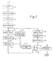
- the device according to the invention comprises a conventional chain for receiving and demodulating a digitized speech signal, coded in DELTA, and transmitted in prefiltered FSK modulation.
- the input E which receives the intermediate frequency signal, is connected to the input of an intermediate frequency filter 1.
- the output of this filter is connected to the input of an intermediate frequency amplifier 2 whose output is connected to the input of a limiter 3.
- the output of the limiter is connected to the input of the frequency discriminator 4, in series with a low-pass smoothing filter whose cut-off frequency is f.
- the output of this low-pass filter 5 is connected to the input of a bit synchronization detection circuit, this circuit detecting the zero-crossings of the output signal of the low-pass filter 5.
- the output of this pass filter -bas is also connected to the input of a sampling and decision circuit 7 having moreover a sampling control input connected to the output of the bit synchronization detection circuit 6.
- Circuit 7 gives the digital value demodulated bit received.
- the output of the decision circuit 7 is coupled to the input of a DELTA decoder 8 reconstituting, with from the digital sequence at the output of the decision circuit 7, the speech signal in analog form.
- the speech interpolation device further comprises a high-pass filter 10, with cut-off frequency f equal to the cut-off frequency of the low-pass filter 5.
- a high-pass filter 10
- cut-off frequency f equal to the cut-off frequency of the low-pass filter 5.
- the output of this filter is connected to the input of a threshold detector circuit 11, this threshold being the level from which it is considered that there is interference.
- this threshold can be the average level of an output signal corresponding to eight decibels of signal-to-noise ratio.
- the output of the threshold detector circuit 11 is connected to the input of a monostable circuit 12 the output of which is connected to the control input of a two-position switch 14. The role of the monostable is to shape the detector circuit output signal to make it suitable for controlling the switch.
- the output of the decision circuit 7 is coupled to the input of the DELTA decoder 8 via a delay circuit 15 and the first channel of the switch 14, first input-output, this output being connected to the input of the DELTA decoder 8.
- the delay circuit 15 has a clock input connected to the output of the bit synchronization detection circuit 6.
- the delay circuit 15 makes it possible to adjust the transit time in the demodulation channel to the duration necessary for the detection of disturbances, so that the detection of faults applies well to the corresponding bits recognized as being erroneous.
- the processing carried out to suppress noise during disturbances consists in replacing the scrambled bits transmitted in the reception chain with a sequence of "rolls" formed by an alternation of 0 and 1.
- the output of the bit synchronization detection circuit 6 is connected to the input of a bearing generator circuit 13, the output of which is connected to the second input of the switch 14.
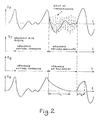
- Figure 2 is a signal diagram which explains this process.
- the first signal represented Sp is the analog speech signal before coding and modulation.
- the modulated signal On reception, the modulated signal is processed by the amplifier 2, the limiter 3, the discriminator 4 and the low-pass filtering 5.
- the monostable 12 which controls the switch 14 associated with the rolling generator 13 makes it possible to replace the sequence of bits "estimated to be scrambled" by a rolling sequence.
- the signal at the input Eg of the DELTA decoder and therefore consists of a succession of sequences estimated to be correct and rolling sequences.
- the speech signal At the output Sg of the DELTA decoder, the coding being adaptive, the speech signal, from the level reached at the end of the sequence estimated to be correct, is gradually reduced to a zero signal. At the end of the interference and when the monostable circuit has returned to its initial state, the speech signal returns to its correct value without discontinuity.
- the DELTA decoder slaves its slope to the minimum value since there is only detection of 1 and 0 successive. Therefore, whatever the signal amplitude before receiving the bearings, the signal amplitude tends to 0 with a time constant which is that of the adaptation loop of the DELTA decoder, ie approximately 4 ms.
- the rolling generator 13 can be a simple D type flip-flop, the inverted output of which is connected to the signal input; the output of the bit synchronization detection circuit, giving the clock rate, is connected to the clock input of flip-flop 13.
- the invention is not limited to the embodiment precisely described and shown.
- the above description is illustrated by an example of the radio voice transmission system.
- This example is not limiting and the interpolation device also applies to a transmission system by wires or radio-relay systems.
- This interpolation device is particularly suitable for packet transmission, the scrambled packets being replaced by rolling sequences.
- interference detection can be done differently and possibly result from the application of several distinct criteria.
- noise detection outside the useful band is particularly effective, since at emission there are no components emitted outside the useful band.
Landscapes
- Engineering & Computer Science (AREA)
- Computer Networks & Wireless Communication (AREA)
- Signal Processing (AREA)
- Noise Elimination (AREA)
Applications Claiming Priority (2)
| Application Number | Priority Date | Filing Date | Title |
|---|---|---|---|
| FR8221875 | 1982-12-28 | ||
| FR8221875A FR2538645B1 (fr) | 1982-12-28 | 1982-12-28 | Procede et dispositif d'interpolation de la parole dans un systeme de transmission de parole numerisee |
Publications (3)
| Publication Number | Publication Date |
|---|---|
| EP0113291A2 true EP0113291A2 (de) | 1984-07-11 |
| EP0113291A3 EP0113291A3 (en) | 1984-08-08 |
| EP0113291B1 EP0113291B1 (de) | 1988-05-18 |
Family
ID=9280566
Family Applications (1)
| Application Number | Title | Priority Date | Filing Date |
|---|---|---|---|
| EP83402525A Expired EP0113291B1 (de) | 1982-12-28 | 1983-12-23 | Verfahren und Einrichtung zur Sprachinterpolation in einem System zur Übertragung von digitalisierter Sprache |
Country Status (4)
| Country | Link |
|---|---|
| US (1) | US4541101A (de) |
| EP (1) | EP0113291B1 (de) |
| DE (1) | DE3376723D1 (de) |
| FR (1) | FR2538645B1 (de) |
Cited By (7)
| Publication number | Priority date | Publication date | Assignee | Title |
|---|---|---|---|---|
| FR2610156A1 (fr) * | 1987-01-22 | 1988-07-29 | Outokumpu Oy | Appareil pour la communication bidirectionnelle dans des installations souterraines |
| US10670740B2 (en) | 2012-02-14 | 2020-06-02 | American Science And Engineering, Inc. | Spectral discrimination using wavelength-shifting fiber-coupled scintillation detectors |
| US10830911B2 (en) | 2018-06-20 | 2020-11-10 | American Science And Engineering, Inc. | Wavelength-shifting sheet-coupled scintillation detectors |
| US11143783B2 (en) | 2002-07-23 | 2021-10-12 | Rapiscan Systems, Inc. | Four-sided imaging system and method for detection of contraband |
| US11175245B1 (en) | 2020-06-15 | 2021-11-16 | American Science And Engineering, Inc. | Scatter X-ray imaging with adaptive scanning beam intensity |
| US11300703B2 (en) | 2015-03-20 | 2022-04-12 | Rapiscan Systems, Inc. | Hand-held portable backscatter inspection system |
| US11340361B1 (en) | 2020-11-23 | 2022-05-24 | American Science And Engineering, Inc. | Wireless transmission detector panel for an X-ray scanner |
Families Citing this family (10)
| Publication number | Priority date | Publication date | Assignee | Title |
|---|---|---|---|---|
| AU560508B2 (en) * | 1984-02-15 | 1987-04-09 | Matsushita Electric Industrial Co., Ltd. | Pay tv delta encoded sound signal processing apparatus |
| DE3446529A1 (de) * | 1984-12-20 | 1986-07-03 | Blaupunkt-Werke Gmbh, 3200 Hildesheim | Verfahren zur stoerverminderung in einer rundfunk-empfangsanlage |
| JPS61184933A (ja) * | 1985-02-12 | 1986-08-18 | Clarion Co Ltd | パルス性雑音除去用信号補償ゲ−ト回路 |
| JPH0752845B2 (ja) * | 1985-10-04 | 1995-06-05 | 日本電気株式会社 | 差分符号化回路 |
| JPH0640627B2 (ja) * | 1987-01-28 | 1994-05-25 | 日本電気株式会社 | 適応型ジツタキヤンセラ |
| US4754467A (en) * | 1987-07-01 | 1988-06-28 | Motorola, Inc. | Digital signal detection with signal buffering and message insertion |
| FR2724519B1 (fr) * | 1994-09-14 | 1996-12-13 | Sgs Thomson Microelectronics | Detecteur de presence d'une transmission dans un modem |
| US6794695B2 (en) | 2002-04-29 | 2004-09-21 | Hewlett-Packard Development Company, L.P. | Magneto resistive storage device having a magnetic field sink layer |
| PL3242315T3 (pl) | 2012-02-03 | 2024-02-19 | Rapiscan Systems, Inc. | Rentgenowski układ inspekcyjny do skanowania obiektu |
| GB2624599A (en) | 2021-10-01 | 2024-05-22 | Rapiscan Holdings Inc | Methods and systems for the concurrent generation of multiple substantially similar X-ray beams |
Family Cites Families (15)
| Publication number | Priority date | Publication date | Assignee | Title |
|---|---|---|---|---|
| US2395737A (en) * | 1943-08-11 | 1946-02-26 | Rca Corp | Angle modulation noise squelching system |
| US3497812A (en) * | 1967-04-24 | 1970-02-24 | Gen Electric | Noise clamping circuit for f.s.k. receiver |
| BE758331A (fr) * | 1969-11-01 | 1971-04-30 | Philips Nv | Circuit permettant de supprimer des parasites dans un recepteurde signaux electriques |
| US3783387A (en) * | 1972-06-14 | 1974-01-01 | Gen Electric | Noise detector circuit |
| FR2405601A1 (fr) * | 1975-12-18 | 1979-05-04 | Trt Telecom Radio Electr | Systeme radioelectrique de transmission d'informations par modulation d'une porteuse a frequence variable par sauts |
| DE2905471B1 (de) * | 1979-02-13 | 1980-02-21 | Siemens Ag | System zum Empfang frequenzmodulierter digitaler Nachrichtensignale |
| JPS54139417A (en) * | 1978-04-21 | 1979-10-29 | Nippon Telegr & Teleph Corp <Ntt> | Interpolation receiving devices at voice short break time |
| CH630498A5 (de) * | 1978-05-11 | 1982-06-15 | Patelhold Patentverwertung | Anordnung zum automatischen umschalten von parallel betriebenen richtfunkanlagen. |
| NL7807171A (nl) * | 1978-06-30 | 1980-01-03 | Philips Nv | Ontvanger voor digitale signalen in lijncode. |
| JPS5514734A (en) * | 1978-07-17 | 1980-02-01 | Nec Corp | Pulse noise elimination circuit |
| DE2907611C2 (de) * | 1979-02-27 | 1981-04-23 | Licentia Patent-Verwaltungs-Gmbh, 6000 Frankfurt | Empfängerauswahlautomatik für Funkzentralen |
| NL184594C (nl) * | 1979-09-04 | 1989-09-01 | Philips Nv | Radio-ontvanger voorzien van een frequentie gesleutelde lus met audiofrequente terugkoppeling, en een stomschakeling. |
| DE3008076C2 (de) * | 1980-03-03 | 1982-05-06 | Siemens AG, 1000 Berlin und 8000 München | Einrichtung zur Empfängerabschaltung bei kleinem Signal-Geräusch-Abstand für ein digital moduliertes Funksystem mit Frequenzmodulation |
| NL189588C (nl) * | 1981-04-01 | 1993-05-17 | Philips Nv | Zender voor hoekgemoduleerde signalen. |
| JPS587933A (ja) * | 1981-07-07 | 1983-01-17 | Nippon Gakki Seizo Kk | インパルスノイズ除去装置 |
-
1982
- 1982-12-28 FR FR8221875A patent/FR2538645B1/fr not_active Expired
-
1983
- 1983-12-23 DE DE8383402525T patent/DE3376723D1/de not_active Expired
- 1983-12-23 EP EP83402525A patent/EP0113291B1/de not_active Expired
- 1983-12-27 US US06/565,715 patent/US4541101A/en not_active Expired - Fee Related
Cited By (10)
| Publication number | Priority date | Publication date | Assignee | Title |
|---|---|---|---|---|
| FR2610156A1 (fr) * | 1987-01-22 | 1988-07-29 | Outokumpu Oy | Appareil pour la communication bidirectionnelle dans des installations souterraines |
| US11143783B2 (en) | 2002-07-23 | 2021-10-12 | Rapiscan Systems, Inc. | Four-sided imaging system and method for detection of contraband |
| US10670740B2 (en) | 2012-02-14 | 2020-06-02 | American Science And Engineering, Inc. | Spectral discrimination using wavelength-shifting fiber-coupled scintillation detectors |
| US11579327B2 (en) | 2012-02-14 | 2023-02-14 | American Science And Engineering, Inc. | Handheld backscatter imaging systems with primary and secondary detector arrays |
| US11300703B2 (en) | 2015-03-20 | 2022-04-12 | Rapiscan Systems, Inc. | Hand-held portable backscatter inspection system |
| US11561320B2 (en) | 2015-03-20 | 2023-01-24 | Rapiscan Systems, Inc. | Hand-held portable backscatter inspection system |
| US10830911B2 (en) | 2018-06-20 | 2020-11-10 | American Science And Engineering, Inc. | Wavelength-shifting sheet-coupled scintillation detectors |
| US11525930B2 (en) | 2018-06-20 | 2022-12-13 | American Science And Engineering, Inc. | Wavelength-shifting sheet-coupled scintillation detectors |
| US11175245B1 (en) | 2020-06-15 | 2021-11-16 | American Science And Engineering, Inc. | Scatter X-ray imaging with adaptive scanning beam intensity |
| US11340361B1 (en) | 2020-11-23 | 2022-05-24 | American Science And Engineering, Inc. | Wireless transmission detector panel for an X-ray scanner |
Also Published As
| Publication number | Publication date |
|---|---|
| US4541101A (en) | 1985-09-10 |
| EP0113291A3 (en) | 1984-08-08 |
| EP0113291B1 (de) | 1988-05-18 |
| FR2538645A1 (fr) | 1984-06-29 |
| DE3376723D1 (en) | 1988-06-23 |
| FR2538645B1 (fr) | 1986-04-11 |
Similar Documents
| Publication | Publication Date | Title |
|---|---|---|
| EP0113291B1 (de) | Verfahren und Einrichtung zur Sprachinterpolation in einem System zur Übertragung von digitalisierter Sprache | |
| EP0950306B1 (de) | Verfahren und vorrichtung zum formen des beschneidungsrauschens einer mehrträgermodulation | |
| EP0054829B1 (de) | Verfahren und Einrichtung zur Detektion der Trainingsfolge eines autoadaptiven Entzerrers | |
| FR2526608A1 (fr) | Appareil de transmission de signaux analogiques et numeriques | |
| BE897704A (fr) | Appareil a signaux analogiques et numeriques | |
| EP0433198B1 (de) | Amplitudenmodulation-Übertragungssystem mit unterdrücktem Träger, das die Polarität des übertragenen Signals erhält | |
| EP0549445B1 (de) | Verfahren zur Übertragung von Referenzsignalen in einem Mehrträgerdatenübertragungssystem | |
| EP0099814A1 (de) | Für Funkverbindungen hoher Frequenz in gestörtem Umfeld ausgelegte Einrichtung zur Wiedergewinnung der Taktfrequenz | |
| CA2060413C (fr) | Procede de detection de signal perturbateur pour demodulateur de donnees numeriques et dispositif de mise en oeuvre d'un tel procede | |
| EP0089276B1 (de) | Taktfrequenzwiedergewinnungseinrichtung für digitale Übertragung | |
| FR2679721A1 (fr) | Procede d'egalisation adaptative reduisant l'interference intersymbole, et dispositif de reception et application correspondants. | |
| EP0854582B1 (de) | Verfahren zur Unterdrückung der Klickgeräusche in einem Datenübertragungssystem | |
| EP0113615B1 (de) | Einrichtung zur Sprachsignalbehandlung in einer Sender-Empfänger-Radioausrüstung, anwendbar für Sprachsignalübertragung und -empfang | |
| EP2351305B1 (de) | Mehrfachzustands-modulations-prozess mit kontinuierlicher phasenmodulation und sender für diesen prozess | |
| EP0317862B1 (de) | Vorrichtung zur Verbesserung des Hörkomforts durch Unterdrückung der Einschwingvorgänge in einer Empfangskette einer FM/PM-Schmalbandeinrichtung, insbesondere für Funkfernsprechen | |
| EP0311494B2 (de) | Verfahren und Einrichtung zur digitalen Sprachübertragung zwischen beweglichen Stationen | |
| EP0316839B1 (de) | Hörverbesserungsschaltung im Falle eines Trägerschwunds in einem schmalbandigen FM/PM-Empfänger | |
| EP0348322B1 (de) | Verfahren zur Auswertung des Gleichstrompegels eines Signals nach der DMAC-Paket-Norm, entsprechende Vorrichtung und Benutzung | |
| EP4016118B1 (de) | Verfahren zur verarbeitung eines durch ein radarsignal gestörten funksignals | |
| EP0822681B1 (de) | Verfahren und System zur Schätzung der Qualität von empfangenen Informationsblöcken über ein Übertragungssystem mit Verwendung von Blockkodierung | |
| EP0821500B1 (de) | Mehrfachdekodierung | |
| CA1287126C (fr) | Procede de detection de faux accrochages du signal de reference sur le signal a demoduler en demodulation numerique coherente et dispositif mettant en oeuvre un tel procede | |
| EP0210093B1 (de) | Methode und Vorrichtung zur Überwachung der Übertragung von Signalen eines Differentialschutzes | |
| FR2768881A1 (fr) | Dispositif de commande de l'echantillonnage d'un signal vehiculant des informations binaires codees selon un codage bi-phase | |
| EP0125984B1 (de) | Verfahren zur Regenerierung von verzerrten digitalen Signalen und Schaltungsanordnung zur Durchführung des Verfahrens |
Legal Events
| Date | Code | Title | Description |
|---|---|---|---|
| PUAI | Public reference made under article 153(3) epc to a published international application that has entered the european phase |
Free format text: ORIGINAL CODE: 0009012 |
|
| PUAL | Search report despatched |
Free format text: ORIGINAL CODE: 0009013 |
|
| AK | Designated contracting states |
Designated state(s): DE GB |
|
| AK | Designated contracting states |
Designated state(s): DE GB |
|
| 17P | Request for examination filed |
Effective date: 19841208 |
|
| GRAA | (expected) grant |
Free format text: ORIGINAL CODE: 0009210 |
|
| AK | Designated contracting states |
Kind code of ref document: B1 Designated state(s): DE GB |
|
| GBT | Gb: translation of ep patent filed (gb section 77(6)(a)/1977) | ||
| REF | Corresponds to: |
Ref document number: 3376723 Country of ref document: DE Date of ref document: 19880623 |
|
| REG | Reference to a national code |
Ref country code: GB Ref legal event code: 746 |
|
| PLBE | No opposition filed within time limit |
Free format text: ORIGINAL CODE: 0009261 |
|
| STAA | Information on the status of an ep patent application or granted ep patent |
Free format text: STATUS: NO OPPOSITION FILED WITHIN TIME LIMIT |
|
| 26N | No opposition filed | ||
| PGFP | Annual fee paid to national office [announced via postgrant information from national office to epo] |
Ref country code: DE Payment date: 19921112 Year of fee payment: 10 |
|
| PGFP | Annual fee paid to national office [announced via postgrant information from national office to epo] |
Ref country code: GB Payment date: 19921118 Year of fee payment: 10 |
|
| PG25 | Lapsed in a contracting state [announced via postgrant information from national office to epo] |
Ref country code: GB Effective date: 19931223 |
|
| GBPC | Gb: european patent ceased through non-payment of renewal fee |
Effective date: 19931223 |
|
| PG25 | Lapsed in a contracting state [announced via postgrant information from national office to epo] |
Ref country code: DE Effective date: 19940901 |