EP0113244B1 - Cell unit for observing electrophoresis - Google Patents
Cell unit for observing electrophoresis Download PDFInfo
- Publication number
- EP0113244B1 EP0113244B1 EP83307936A EP83307936A EP0113244B1 EP 0113244 B1 EP0113244 B1 EP 0113244B1 EP 83307936 A EP83307936 A EP 83307936A EP 83307936 A EP83307936 A EP 83307936A EP 0113244 B1 EP0113244 B1 EP 0113244B1
- Authority
- EP
- European Patent Office
- Prior art keywords
- diaphragm
- pair
- cell unit
- measurement cell
- liquid
- Prior art date
- Legal status (The legal status is an assumption and is not a legal conclusion. Google has not performed a legal analysis and makes no representation as to the accuracy of the status listed.)
- Expired
Links
Images


Classifications
-
- G—PHYSICS
- G01—MEASURING; TESTING
- G01N—INVESTIGATING OR ANALYSING MATERIALS BY DETERMINING THEIR CHEMICAL OR PHYSICAL PROPERTIES
- G01N27/00—Investigating or analysing materials by the use of electric, electrochemical, or magnetic means
- G01N27/26—Investigating or analysing materials by the use of electric, electrochemical, or magnetic means by investigating electrochemical variables; by using electrolysis or electrophoresis
- G01N27/416—Systems
- G01N27/447—Systems using electrophoresis
Definitions
- This invention is concerned with a cell unit for observing an electrophoresis, more particularly with a measurement or measuring cell unit for observing an electrophoresis of living cells by means of a microscope.
- Apparatus adapted to measure the velocities of minute or fine particles such as living cells in a liquid specimen under the effect of an electric field and calculate the electrophoretic mobility of the particles have been well-known and generally referred to as a living cell electrophoresis apparatus or electrophoretic apparatus for living cells.
- a living cell electrophoresis apparatus or electrophoretic apparatus for living cells Upon observing or measuring the velocities or the electrophoretic mobility or mobilities of the particles in the liquid specimen, flow or turbulence of the liquid specimen which affects the movement of particles to cause errors in observed or measured values has to be eliminated as much as possible.
- the measurement cell system in the electrophoretic apparatus generally comprises a unit including a measurement cell, electrodes for giving the electric potential gradient to the liquid specimen in the measurement cell, diaphragms formed by substantially rigidly supported membranes, valves for sealing the specimen in the measurement cell (hereinafter referred to as sealing valves) and so on.
- the diaphragm formed by the substantially rigidly supported membrane serves for preventing the gas or bubbles produced at surfaces of the electrodes in the course of the electrode reaction from entering the measurement cell.
- the diaphragm is made of a substantially rigidly supported porous membrane such as an ion-exchange membrane or a dialysis membrane and, in conventional measurement cell units, have been designed to be secured by an adequate means such as a perforated plate so that they may not be bent nor displaced.
- Each of the sealing valves which are disposed in ducts as conduits for introducing and discharging the liquid specimen into and from the measurement cell generally comprises a cock made of glass, or a sluice valve made from Teflon (Trade Mark; polytetrafluoroethylene).
- a pinch valve or a pinch cock designed to nip or pinch a flexible or resilient tube to close the liquid passage in the tube has been considered unsuitable for the sealing valve, because it deforms the flexible tube upon pinching to affect the liquid specimen to be sealed, that is, it causes the undesired flow or turbulence of the liquid specimen due to the change in the inner pressure of the tube upon sealing or confining the liquid specimen in a limited space including the space in the measurement cell.
- the conventional valve such as the glass cock and the teflon sluice valve do not cause the sealed liquid specimen to move or flow
- the sealing performances of these valves are not adequate butthe sealing performance or degree of the sealing of the valves fluctuates or varies on every opening and closing operation of the valves, and thus desired stability can not always be obtained in the measurements or observations of the living cell electrophoresis.
- the inventors have chosen a pinch valve having a good sealing performance as the sealing valve while making an attempt to solve the problem of the flow of the liquid specimen attributable to the use of the pinch valve by the improvement in other part of the cell unit, and have accomplished this invention.
- the object of this invention is to provide a measurement cell unit for observing electrophoresis in which a liquid specimen can be sealed in a predetermined space easily and adequately and the flow of the liquid specimen in the measuring cell upon sealing can be minimized.
- a cell unit for observing an electrophoresis comprising
- both of the pair of conduit means have portions made of flexible tubes
- the measurement cell is made of an optically transparent material so as to allow the observation of the electrophoretic behavior of the charged particles in the liquid specimen by means of the microscope.
- One of the features of this invention is to use a flexible or resilient polymeric material as the conduit means or duct for introducing and/or discharging the liquid specimen into and/or from the measurement cell and to use the pinch valve as the sealing valve.
- Another feature of this invention is to dispose the diaphragm displaceably so that the fluctuation of the pressure can be suppressed or absorbed in the space defined by the diaphragms and the pinch valves.
- a preferred embodiment of the measurement cell unit according to this invention is adapted to absorb the undesirable effect of the pinch valve on the liquid specimen by utilizing the bending displacement of the flexible diaphragm or partition membrane which allows some ion to pass therethrough.
- the flexible diaphragm or partition membrane used in this invention may be designed as a so-called mechanical diaphragm in which the membrane is not secured as in the conventional cell unit, for example, by a perforated plate or the like, but freely displaceable depending on the fluctuation in the pressure of the liquid specimen.
- the diaphragm can be made displaceable by securing the peripheral part thereof displaceably to a conduit which is connected to the measurement cell unit by way of a separate flexible membrane or bellows.
- a piston-like member slidably fitted into the conduit of a cylinderlike tube situated between the measurement cell unit and the electrode housing may be formed with an opening at the end face thereof and a partition membrane may be secured to the end face at a peripheral portion thereof so as to cover the opening.
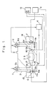
- Fig. 1 schematically shows an example of an apparatus for observing electrophoresis by means of the microscope.
- a liquid specimen is introduced or supplied through an opened sealing valve 1 or 2 into an optically transparent measurement cell 3.
- the measurement cell 3 is kept at a constant temperature within a thermostat bath 5 externally equipped with a temperature control mechanism 4 for maintaining the temperature at a predetermined level.
- the sealing valves 1 and 2 are closed and an electric field or electric potential gradient is applied to the liquid specimen in the measurement cell 3 by a DC constant-current power supply 8 through a pair of electrodes 6 and 7 disposed on both sides of the measurement cell 3.
- the liquid specimen or the charged particles in the liquid in the measurement cell 3 is moved by the electric field thus applied or the electric potential gradient thus produced and the velocities of the specimen or of the charged particles in the liquid is observed or measured by means of the microscope through a view window 9. After the measurement, the liquid specimen is discharged from the opened sealing valve 1 or 2.
- the measurement cell 3 has glass tubes 10a, 10b on its both ends. The glass tubes 10a, 10b are connected to the sealing valves 1 and 2 respectively at their one ends 10c, 10d.
- Electrodes 15, 16 made of platinum for voltage measurement are protruded at their top ends 17, 18 into the passages in the glass tubes 10a, 10b, and are electrically connected to input terminals 20, 21 of a voltmeter 19.
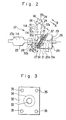
- Fig. 2 is a schematic view of a part of a cell unit 22 for observing electrophoresis according to this invention.
- a measurement cell 23 is connected to a flexible tube 24 and coupled with an electrode 26 similar to the electrode 7 for applying electric field to the liquid specimen in the cell 23 through a diaphragm 25 which allows the electric current to pass therethrough.
- the similar or same components are symmetrically provided at the left-hand side of the measurement cell 23 with the components at the right-hand side of the measurement cell 23 shown in Figure 2 just like the measurement cell unit in Figure 1, that is another flexible tube similar to the tube 24, another diaphragm similar to the diaphragm 25, another electrode similar to the electrode 26, etc. are also provided at the left-hand side of the cell 23 of Fig. 2, but the explanation will be made only to the right-hand part of the cell 23 for the sake of the simplicity.
- the diaphragm or partition membrane 25 is held at a peripheral portion 25a thereof in a liquid and air-tight manner through a gasket 32 between subblocks 30 and 31 integrally secured with each other by means of screws 29 at an outside position of a corner of the passage 30a from a valve 36 to the cell 23 where the passage 30a is bent.
- the gasket 32 has an opening 33 for allowing a central portion 25b of the diaphragm 25 to be displaced in the direction A or B, and supports the outer peripheral edge 25a of the partition membrane 25 at the peripheral edge 34 of the opening 33.
- the gasket 32 is formed with apertures 35 for insertion of the screws 29.
- the subblock 31 serves for the electrode housing accommodating the electrode 26 and electrolyte in its chamber or space 31a which is separated from the passage 30b and the space or chamber 23a by the diaphragm 25a, and is substantially kept at an atmospheric pressure.
- a pinch valve generally represented by the reference numeral 36 seals or confines the liquid specimen in the measurement cell 23 by pinching or nipping the flexible tube 24 which is liquid-tightly connected to the tube portion 30c of the subblock 30.
- the diaphragm or partition membrane 25 is constituted as a mechanical diaphragm freely displaceable at the free central part 25b in the direction A or B by the conventional method using the gasket 32 composed of a flat packing, O-ring or the like so as to support only the peripheral portion 25a of the diaphragm 25.
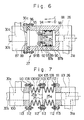
- the circular perforated plates 80, 81 can be disposed in circular recesses 82,83 formed the subblocks 30, 31 and supported by protruding portions 84, 85.
- the circular perforated plates 80, 81 can have cut-out portions 86 for enabling to mount or dismount the circular perforated plates 80, 81 into or from the circular recesses 82, 83 through protruding portions 84, 85 as shown in Figure 5.
- the diaphragm 25 may be linearly displaced as a whole as shown in Figure 6 or 7 where components substantially identical with the components in Figure 3 are represented by the same reference numeral.
- the block 27 comprises subblocks 87 and 88 similar to the subblocks 30, 31 respectively, and the diaphragm 25 is fixed to one end 89 of an annular piston-like member 90, which is fitted slidably in the directions C, D in an enlarged cylindrical bore 91 of the subblock 88, by means of sealing rings 92, 93, an annular retainer member 94 and screws 95.
- the subblock 87 is liquid-tightly connected to the subblock 88 through sealing ring 96.
- the end face 99 of the subblock 87 and the end face 98 of the bore 91 serve for restricting the displacement of the piston-like member 90 in the direction D, C respectively.
- References 87a, 87b are sealing rings.
- the block 27 comprises subblocks 100 and 101, and the diaphragm 25 is supported at its peripheral 25a through sealing rings or gaskets 102, 103 between one annular ends 104, 105 of two generally hollow cylindrical bellows 106, 107 whose other ends 108,109 are fixed to the flanged ends 110, 111 of the subblocks 100, 101 respectively.
- Reference numeral 112 represents a sealing ring for liquid-tight seal and reference numeral 113 represents securing means such as a screw and nut.
- the diaphragm 25 can be generally freely displaced in the directions C, D as a whole according to the displacement of the piston-like member 90 or to the expansion or contraction of the bellows 106, 107 and that the free central-portion 25b of the diaphragm 25 can be displaced in the directions C, D by being bent.
- the diaphragm 25 may be made of a dialysis membrane, an ion exchange membrane or other membrane which has been conventionally employed in the cell unit for observing the electrophoresis.
- the membrane or diaphragm area is usually less than 100 mm 2 and, preferably, within a range between 50-3 mm 2 although it may be varied depending on the thickness of the membrane.
- the membrane area is related with two factors of the diaphragm 25, that is, the performance or function and the strength of the diaphragm.
- the diaphragm 25 is displaced in the direction A(D) or B(C) respectively and enables to suppress or prevent the pressure fluctuation in the liquid specimen within the space 37 from propagating to the liquid specimen within the measurement cell 23 at least due to the distortion at the central part 25b thereof in the direction A or B depending on the pressure fluctuation, that is, the diaphragm 25 absorbs the pressure fluctuation or change.
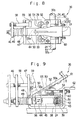
- a pinch valve of a structure for example, as shown in Fig. 8 and Fig. 9 is used as the pinch valve 36, but other known pinch valves such as those generally referred to as a pinch cock may be used.
- the pinch valve 36 shown in Fig. 8 and Fig. 9 comprises a frame member 38 and a valve body 39 secured to the frame member 38.
- the valve body 39 has an aperture 42 for passing therethrough a flexible or resilient tube 24 composed of integral flexible or resilient tubular parts 40, 41 and also has a cylindrical hole 45 containing, fitted therein, a stationary pinching or nipping member 43 in the form of a semi- or partial cylinder and a plunger-like pinching or nipping member 44 movable in the direction E or F perpendicular to the extending direction of the aperture 42.
- a grip wall member 46 is secured opposing to a wall portion 47 of the frame member 39 at the protruded end of the nipping member 44 passing through an aperture 48 in the grip wall portion 47.
- a spring 49 is mounted between the grip wall portion 47 and the grip wall member 46 for biasing the grip wall member 46 in the direction F apart from the grip wall portion 47.
- a stop member 50 adapted to stop the nipping member 44 is made pivotable around a shaft part 54 of a U-shaped pivot shaft member 53 supported by a protruding wall portion 51 of the frame member 38 and a retainer member 52 secured to the valve body 39 in the direction G or H while biased by a spring 55 in the direction G by a spring 55 which is supported by a pin 55a disposed in a recess of the stop member 50.
- the spring 55b shown in Fig.
- the stop member 50 may be mounted around the shaft part 54 of the U-shaped member 53 so as to bias the stop member 50 in the direction G if desired, for example, in the case where it is difficult to form a space or recess for mounting the pin 55a and the spring 55 in the stop member 50 because of its small size.
- Reference numeral 58 represents a guide member for guiding the nipping member 44 in the direction E or F
- reference numeral 59 represents a stop member for restricting the displacement of the nipping or seizing member 44 in the direction F within an appropriate range
- reference numeral 60 represents a nut for adjusting the position of the shaft part 54 in the direction E or F.
- the passage 37a in the flexible or resilient tube 24 can be closed completely, for instance, by merely gripping the grip wall members 46 and 47 between fingers so as to bring them closer to each other against expansion of the spring 49 and the closed passage 37a in the flexible tube 24 can be opened, for example, by gripping the two end parts 61, 62 between fingers so as to bring them closer to each other because the engagement between the engaging portion 57 and hole 56 can be released allowing the nipping member to be displaced in the direction F by the spring 49.
- Fig. 10 shows a perforated plate 63 composed of a Teflon ring 64 inserted with a porous glass product 65, a gasket 67, and diaphragm 66 formed by a membrane substantially rigidly supported between the perforated plate 63 and the gasket 67.
- a cation exchange membrane (0.3 mm thickness, 25 mm 2 membrane area) was used as the diaphragm and the pinch valve shown in Figs. 8 and 9 was used as the sealing valve.
- Measurement was carried out twice by reversing the orientation of the electric field or polarities of the electrodes 6, 7 and the data showing the difference within 10% between the rightward and leftward velocities were employed judging that the operating condition of each measurement cell unit was stable during the measuring period.
- the mobility (pm/seclvolttcm) was measured for each of 50 erythrocyte cells in one liquid specimen and the mean value for the 50 cells was determined as the mobility of the specimen. Such measurement was repeated for 20 times to determine the standard deviation of the mobility of the specimen, in which the standard deviation was within 1-2% in a case of using the cell unit according to this invention, whereas it was 3-4% in the conventional cell unit employing the diaphragm formed by the substantially rigidly supported membrane shown in Fig. 10.
Landscapes
- Health & Medical Sciences (AREA)
- Life Sciences & Earth Sciences (AREA)
- Molecular Biology (AREA)
- Chemical & Material Sciences (AREA)
- Chemical Kinetics & Catalysis (AREA)
- Electrochemistry (AREA)
- Physics & Mathematics (AREA)
- Analytical Chemistry (AREA)
- Biochemistry (AREA)
- General Health & Medical Sciences (AREA)
- General Physics & Mathematics (AREA)
- Immunology (AREA)
- Pathology (AREA)
- Investigating Or Analysing Biological Materials (AREA)
Applications Claiming Priority (2)
| Application Number | Priority Date | Filing Date | Title |
|---|---|---|---|
| JP234554/82 | 1982-12-29 | ||
| JP57234554A JPS59125051A (ja) | 1982-12-29 | 1982-12-29 | 細胞電気泳動測定セルユニツト |
Publications (3)
| Publication Number | Publication Date |
|---|---|
| EP0113244A2 EP0113244A2 (en) | 1984-07-11 |
| EP0113244A3 EP0113244A3 (en) | 1985-03-27 |
| EP0113244B1 true EP0113244B1 (en) | 1987-05-20 |
Family
ID=16972839
Family Applications (1)
| Application Number | Title | Priority Date | Filing Date |
|---|---|---|---|
| EP83307936A Expired EP0113244B1 (en) | 1982-12-29 | 1983-12-23 | Cell unit for observing electrophoresis |
Country Status (6)
| Country | Link |
|---|---|
| US (1) | US4617104A (ja) |
| EP (1) | EP0113244B1 (ja) |
| JP (1) | JPS59125051A (ja) |
| CA (1) | CA1205861A (ja) |
| DD (1) | DD214452A5 (ja) |
| DE (1) | DE3371697D1 (ja) |
Families Citing this family (3)
| Publication number | Priority date | Publication date | Assignee | Title |
|---|---|---|---|---|
| US4801366A (en) * | 1987-03-18 | 1989-01-31 | Godfrey Jamie E | Apparatuses and methods for analyzing macro-ions at electrophoretic steady state |
| FR2708346B1 (fr) * | 1993-07-27 | 1995-10-13 | Caen Basse Normandie Universit | Dispositif permettant de mesurer la mobilité électrophorétique. |
| JP2924815B2 (ja) * | 1996-09-27 | 1999-07-26 | 日本電気株式会社 | ゼータ電位測定装置 |
Family Cites Families (6)
| Publication number | Priority date | Publication date | Assignee | Title |
|---|---|---|---|---|
| GB1333796A (en) * | 1970-06-02 | 1973-10-17 | Lkb Produkter Ab | Electrophoresis |
| SE390766B (sv) * | 1972-12-19 | 1977-01-17 | Lkb Produkter Ab | Forfarande vid motflodesisotachofores |
| SE386742B (sv) * | 1973-11-14 | 1976-08-16 | Lkb Produkter Ab | Apparat for preparativ, isotachoforetisk separation i mikroskala |
| CS178550B1 (en) * | 1974-08-21 | 1977-10-31 | Mirko Deml | Isotachophoretic column |
| US4203817A (en) * | 1979-03-06 | 1980-05-20 | Jenoptik Jena G.M.B.H. | Method of and device for moving liquid samples |
| JPS59107254A (ja) * | 1982-12-10 | 1984-06-21 | Kureha Chem Ind Co Ltd | 電気泳動測定セルユニツト |
-
1982
- 1982-12-29 JP JP57234554A patent/JPS59125051A/ja active Granted
-
1983
- 1983-12-19 US US06/563,249 patent/US4617104A/en not_active Expired - Fee Related
- 1983-12-22 CA CA000444059A patent/CA1205861A/en not_active Expired
- 1983-12-23 EP EP83307936A patent/EP0113244B1/en not_active Expired
- 1983-12-23 DE DE8383307936T patent/DE3371697D1/de not_active Expired
- 1983-12-28 DD DD83258776A patent/DD214452A5/de not_active IP Right Cessation
Also Published As
| Publication number | Publication date |
|---|---|
| US4617104A (en) | 1986-10-14 |
| CA1205861A (en) | 1986-06-10 |
| DD214452A5 (de) | 1984-10-10 |
| JPS59125051A (ja) | 1984-07-19 |
| DE3371697D1 (en) | 1987-06-25 |
| EP0113244A2 (en) | 1984-07-11 |
| JPS6355021B2 (ja) | 1988-11-01 |
| EP0113244A3 (en) | 1985-03-27 |
Similar Documents
| Publication | Publication Date | Title |
|---|---|---|
| Mackereth | An improved galvanic cell for determination of oxygen concentrations in fluids | |
| US4283262A (en) | Analysis system | |
| JP3130967B2 (ja) | 電気化学制御バルブ | |
| US4227984A (en) | Potentiostated, three-electrode, solid polymer electrolyte (SPE) gas sensor having highly invariant background current characteristics with temperature during zero-air operation | |
| EP0113244B1 (en) | Cell unit for observing electrophoresis | |
| GB2119522A (en) | Method and means for electrode calibration | |
| Gittens et al. | An improved microelectrophoresis apparatus and technique for studying biological cell surfaces | |
| Inch | Problems associated with the use of the exposed platinum electrode for measuring oxygen tension in vivo | |
| US3725236A (en) | Electrochemical oxygen demand apparatus | |
| US3917523A (en) | Electrochemical electrode structure | |
| US3960498A (en) | Electrochemical analysis system | |
| US4455213A (en) | Pressure equalization system for membrane type amperometric sensors | |
| US3509035A (en) | Continuous particle electrophoresis cell | |
| US3681205A (en) | Method and cell for repetitive high precision ph and like measurements | |
| US4515676A (en) | Cell unit for observing electrophoresis | |
| US3929603A (en) | Electrolytic sensor with pressure compensating means | |
| Dummett et al. | The influence of the underlying surface on the cataphoretic mobility of adsorbed proteins | |
| US3871990A (en) | Electroosmotic osmometer | |
| US3717565A (en) | Ion-responsive electrode construction | |
| US4801366A (en) | Apparatuses and methods for analyzing macro-ions at electrophoretic steady state | |
| US5253539A (en) | Analyzer system | |
| SU949420A1 (ru) | Ячейка дл микроскопического измерени подвижности коллоидных частиц | |
| US3443856A (en) | Electrical apparatus utilizing a dielectric medium | |
| US3170380A (en) | Pressure responsive device | |
| Tasaka et al. | Relaxation of polymer chains dissolved in the liquid phase of membranes under a pressure gradient |
Legal Events
| Date | Code | Title | Description |
|---|---|---|---|
| PUAI | Public reference made under article 153(3) epc to a published international application that has entered the european phase |
Free format text: ORIGINAL CODE: 0009012 |
|
| AK | Designated contracting states |
Designated state(s): CH DE FR GB LI NL SE |
|
| PUAL | Search report despatched |
Free format text: ORIGINAL CODE: 0009013 |
|
| AK | Designated contracting states |
Designated state(s): CH DE FR GB LI NL SE |
|
| 17P | Request for examination filed |
Effective date: 19850316 |
|
| 17Q | First examination report despatched |
Effective date: 19860725 |
|
| GRAA | (expected) grant |
Free format text: ORIGINAL CODE: 0009210 |
|
| AK | Designated contracting states |
Kind code of ref document: B1 Designated state(s): CH DE FR GB LI NL SE |
|
| REF | Corresponds to: |
Ref document number: 3371697 Country of ref document: DE Date of ref document: 19870625 |
|
| ET | Fr: translation filed | ||
| PLBE | No opposition filed within time limit |
Free format text: ORIGINAL CODE: 0009261 |
|
| STAA | Information on the status of an ep patent application or granted ep patent |
Free format text: STATUS: NO OPPOSITION FILED WITHIN TIME LIMIT |
|
| 26N | No opposition filed | ||
| PGFP | Annual fee paid to national office [announced via postgrant information from national office to epo] |
Ref country code: GB Payment date: 19901212 Year of fee payment: 8 |
|
| PGFP | Annual fee paid to national office [announced via postgrant information from national office to epo] |
Ref country code: SE Payment date: 19901214 Year of fee payment: 8 |
|
| PGFP | Annual fee paid to national office [announced via postgrant information from national office to epo] |
Ref country code: FR Payment date: 19901215 Year of fee payment: 8 |
|
| PGFP | Annual fee paid to national office [announced via postgrant information from national office to epo] |
Ref country code: NL Payment date: 19901231 Year of fee payment: 8 |
|
| PGFP | Annual fee paid to national office [announced via postgrant information from national office to epo] |
Ref country code: CH Payment date: 19910121 Year of fee payment: 8 |
|
| PGFP | Annual fee paid to national office [announced via postgrant information from national office to epo] |
Ref country code: DE Payment date: 19910131 Year of fee payment: 8 |
|
| PG25 | Lapsed in a contracting state [announced via postgrant information from national office to epo] |
Ref country code: GB Effective date: 19911223 |
|
| PG25 | Lapsed in a contracting state [announced via postgrant information from national office to epo] |
Ref country code: SE Effective date: 19911224 |
|
| PG25 | Lapsed in a contracting state [announced via postgrant information from national office to epo] |
Ref country code: LI Effective date: 19911231 Ref country code: CH Effective date: 19911231 |
|
| PG25 | Lapsed in a contracting state [announced via postgrant information from national office to epo] |
Ref country code: NL Effective date: 19920701 |
|
| NLV4 | Nl: lapsed or anulled due to non-payment of the annual fee | ||
| GBPC | Gb: european patent ceased through non-payment of renewal fee | ||
| PG25 | Lapsed in a contracting state [announced via postgrant information from national office to epo] |
Ref country code: FR Effective date: 19920831 |
|
| REG | Reference to a national code |
Ref country code: CH Ref legal event code: PL |
|
| PG25 | Lapsed in a contracting state [announced via postgrant information from national office to epo] |
Ref country code: DE Effective date: 19920901 |
|
| REG | Reference to a national code |
Ref country code: FR Ref legal event code: ST |
|
| EUG | Se: european patent has lapsed |
Ref document number: 83307936.1 Effective date: 19920704 |