EP0112158A2 - Systeme zur Verschleierung von Audiofrequenzsignalen - Google Patents
Systeme zur Verschleierung von Audiofrequenzsignalen Download PDFInfo
- Publication number
- EP0112158A2 EP0112158A2 EP83307584A EP83307584A EP0112158A2 EP 0112158 A2 EP0112158 A2 EP 0112158A2 EP 83307584 A EP83307584 A EP 83307584A EP 83307584 A EP83307584 A EP 83307584A EP 0112158 A2 EP0112158 A2 EP 0112158A2
- Authority
- EP
- European Patent Office
- Prior art keywords
- frames
- signal
- control signal
- time
- base
- Prior art date
- Legal status (The legal status is an assumption and is not a legal conclusion. Google has not performed a legal analysis and makes no representation as to the accuracy of the status listed.)
- Withdrawn
Links
Images


Classifications
-
- H—ELECTRICITY
- H04—ELECTRIC COMMUNICATION TECHNIQUE
- H04K—SECRET COMMUNICATION; JAMMING OF COMMUNICATION
- H04K1/00—Secret communication
- H04K1/06—Secret communication by transmitting the information or elements thereof at unnatural speeds or in jumbled order or backwards
Definitions
- This invention relates to scrambling systems for audio frequency signals. Such systems may, for example, be used in pay television broadcast systems.
- scrambling systems for audio frequency signals are used in radio communication systems and in magnetic recording systems.
- An example of the former is a pay television broadcast system in which a broadcasting station (transmitter) and a user (receiver) conclude a contract whereby the user pays the broadcasting station for taking a particular television broadcast programme.
- a scrambling system is used for the audio frequency signals, so that only the users having contracts with the broadcasting station can satisfactorily receive the particular television broadcast.
- An example of the latter is a so-called automatic answering telephone in which information is recorded secretly by employing a scrambling system, so that the content of the information can only be reproduced intelligibly by a person using a predetermined decoder.
- -Scrambling systems can be classified very generally into those in which the audio signal data are re-arranged on its frequency axis, and those in which the audio signal data is re-arranged on its time-base.
- the present invention concerns the latter systems.
- Such systems include those in which the polarity. of the sampled value of an audio signal is changed in accordance with a predetermined rule; those in which the audio signal is divided into frames on the time-base and then the order of the sampled values is changed within one frame; and those in which whole such frames are changed in order.
- the audio signal after being re-arranged in order occupies a wider frequency band than the original audio signal, so that if it is passed over a path of restricted band-width, distortion occurs in the re-arranged or decoded audio signal.
- the last system mentioned above has fewer such defects. In this case, however, because the order of. the frames is changed, the audio signal changes abruptly at the junctions of the frames, and as a result the decoded audio signal is noisy.
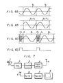
- the audio signal is divided into blocks Bi on the time-base.
- Each of the blocks Bi is formed of four frames f l , f 2 , f 3 and f 4 .
- the frames f,, f 2 , f 3 and f 4 are arranged in the sequential order of Figure 1B of the accompanying darwings, namely, in the sequential order of the frames f 4 , f 3 , f 2 and f l'
- the audio signal thus obtained rises or falls abruptly at the boundaries between the frames.
- this audio signal is passed over a path having a narrow transmission band region, and particularly if the transmission path does not allow high frequency components through, the signal waveform is blunted.
- the audio signal is re-arranged or decoded at the receiver, the original audio signal is distorted or noise is superimposed upon the original audio signal.
- a scrambling system for an audio frequency signal in which an audio signal is divided into blocks, each block being formed of a plurality of frames, said plurality of frames are re-arranged on a time-base in a predetermined order within every block so as to be encoded, and said encoded signal is re-arranged on the time-base in the original order so as to be decoded, characterised by:
- an audio signal is divided into blocks Bi, each block being formed of a plurality of frames f l , f 2 ... f n as shown in Figure 2A.
- the frames f l , f 2 ... f n are re-arranged on the time-base in a predetermined order within every block Bi.
- the frames f 1 , f 2 ... f n thus arranged are sequentially represented as frames g l , g 2 ... g n on the time-base as shown in Figure 2B . Redundant portions R 1 , R 2 .. .
- R n are respectively inserted between the adjacent frames g 1 , g 2 , g 3 ... g n , thus providing blocks ⁇ i. Then, in order that the time-base length of the blocks ⁇ i thus obtained may have the same time-base length of the original blocks Bi, time-base compression is performed to produce block ⁇ i', as shown in Figure 2C. After this encoding, transmission (or recording and reproduction) is performed. On decoding, the redundant portions R 1 ', R 2 ' ... R n ' (formed by time-base compressing the redundant portions R 1 , R 2 ...
- the signal into which the redundant portions R l , R 2 ... R n has been inserted is transmitted by radio communication or through the transmission path of a magnetic recorder, and the redundant portions R 1 , R 2 ... R n form interpolation data to reduce the discontinuity at the boundaries of the frames of the transmitted signal. Also, even if such discontinuity still remains, it is possible to prevent the frame itself from being affected by the discontinuity. Thus, the received or reproduced signal has less noise.
- this control signal can be transmitted with the audio signal.
- the number n of the frames f l , f 2 ... f forming the block Bi and the length 1 of each frame can be selected variously.
- the storage capacity of the encoder and of the decoder and the required degree of secrecy are considered.
- the block Bi is formed of 2, 3 and 4 frames and the frame lengths I thereof are selected to be 8 mS, 16 mS, 32 mS, 65 mS and 130 mS
- the content of the audio signal can be discriminated with the frame lengths 1 of 8 mS and 16 mS at any frame construction.
- Scrambling is established when the frame length 1 is equal to or longer than 32 mS and the scrambling when the frame lengths I are 65 mS and 130 mS is strong.
- the selection depends on the kind of audio signal. For example, for sound such as conversation, there are a large number of changes of sound so that the frame length 1 of the frames f l , f 2 ... f n is selected to be small, while in music, there is less change of sound, so that it is desired to select the frame length 1 of the frames f 1 , f 2 ... f n to be large.
- the redundant portion is formed from interpolation data of the audio signal.
- each block Bi provided by dividing the audio signal is formed of four frames f 1 , f 2 , f 3 and f 4 (see Figure 3A).
- the frame length is selected to be 62.5 mS and the block length is selected to be 250 mS (62.5x4).
- interpolation data portions r 1 , r 2 , r 3 and r 4 are respectively inserted between the adjoining frames of the frames g 1 , g 2 , g 3 and g 4 ( Figure 3B).
- the length of each of these interpolation data portions r 1 r 2 , r 3 and r 4 is selected as, for example, 4 mS.
- the unchanged audio signal is used as these interpolation data portions r 1 , r 2 , r 3 and r 4 . That is, the interpolation data portion r 1 just before the frame g 1 (f 4 ) is used as the rear edge portion of the frame f 3 (shown by.scattered points in Figure 3A).
- FIG. 4 a waveform ( Figure 4A) which is initially continuous is made discontinuous ( Figure 4B) by the re-arrangement of the order.
- This waveform discontinuity occurs at the boundary portion between, for example, the frames g 1 and g 2 .
- the waveform between time points t 1 and t 2 in Figure 4A is inserted into the above discontinuous portion as the interpolation data r 2 thereby to keep the continuity over the range from the interpolation data r 2 to the frame g 2 as shown in Figure 4C.
- interpolation data portions r 1 , r 3 and r4 just before the frames g 1 (f 4 ), g 3 (f 2 ) and g 4 (f 1 ) are respectively used as the rear edge portions of the frames f 3 , f 1 and f4 of the preceding frames.
- the interpolation data portions r 1 ', r 2 ', r 3 ' and r 4 ' are removed, and the frames g 1 ', g 2 ', g 3 ' and g 4 ' are re-arranged in the original sequential order.
- the frames f 1 ', f 2 ', f 3 ' and f 4 ' are re-arranged in this order (see Figure 3D) thereby to produce the block Bi'.
- the block Bi' is time-base-expanded at the time-base-expanding ratio of 266/250 so as to produce the audio signal formed of the block Bi ( Figure 3E).
- this audio signal is not substantially affected by the discontinuity of the waveform due to the re-arrangement of the order upon encoding, so that the signal-to-noise ratio thereof is good.
- a predetermined waveform-forming circuit to produce artificial waveforms usable as the interpolation data r l , r 2 , r 3 and r 4 .
- a waveform W 1 as shown in Figure 5A can be employed as the interpolation data r 1 to r 4 .
- a waveform W 2 which can present a continuity held at both ends of the interpolation data portions r l , r 2 ... If the waveform W 2 is employed, the length of each of the interpolation data portions r 1 , r 2 ... can be reduced.
- control signal intervals other than the audio information are provided in front of the interpolation data portions r 1 and r 2 , into which a control signal CL is inserted as a timing signal of, for example, the re-arrangement of the order.
- the lengths of the interpolation data portions r 1 and r 2 are predetermined so as to prevent the frames g 1 and g 2 from being affected by the control signal CL and the preceding distontinuous portion.
- control signal intervals into which the control signal CL is inserted.
- control signal CL is transmitted together with the audio signal and is then used as the timing signal of, for example, the re-arrangement of the sequential order, the discontinuity at the connection portion between the audio signals can be removed, so that the quality of the sound can be improved.
- a synchronizing signal of a frame period and a synchronizing signal of a block period are transmitted as the control signal CL.
- Figure 7 shows a case in which the present invention is applied to a pay television broadcast system.
- an audio signal from a microphone 1 is amplified by an amplifier 2 and then fed to an encoder 3.
- the encoder 3 will be described in detail later (see Figure 8).
- the audio signal encoded by the encoder 3 is supplied to a transmitter 4 and then transmitted through a transmitting antenna 5.
- the encoded audio signal thus transmitted is received by a receiving antenna 5' and decoded through a tuner 6 by a decoder 7 which will be described in detail later, for supply to a television receiver 8.
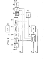
- the encoder 3 may be as shown in Figure 8, and comprise an input terminal 9, with the audio signal from the amplifier 2 ( Figure 7) being supplied through the input terminal 9 and a low-pass filter 10 to a sample and hold circuit 11 in which it is sampled and held, before being supplied to an analog-to-digital (A/D) converter 12.
- the sample and hold circuit 11 and the A/D converter 12 are controlled by a timing controller 14 to which the synchronizing signal is supplied from a terminal 13.
- the audio signal is converted from analog data to digital data.
- the resulting digital data is supplied through a signal processor 15 to a random access memory (RAM) 16 to be written therein.
- the data is read out from the RAM 16.
- To the signal processor 15 is supplied a pattern information regarding the arrangement order previously set in a pattern generator 18 in accordance with a key code supplied from a terminal 17 under the control of the timing controller 14.
- the memory areas of the RAM 16 are taken as 1, 2, 3 , 4 , 5, 6, 7 and 8 and the abscissa x is formed corresponding thereto, while the elapse of time is indicated on the ordinate y. Then, the writing in the RAM 16 is performed as shown by solid line arrows, while the reading of the RAM 16 is performed by broken line arrows.
- data D 1 corresponding to the frame f l in the block Bi is first written in the memory area 1 and then data D 2 , D 3 and D 4 respectively corresponding to the frames f 2 , f 3 and f4 are written in the memory areas 2, 3 and 4 in turn.
- the data D 1 , D 2 , D 3 and D 4 respectively corresponding to the frames f l , f 2 , f 3 and f4 in a block Bi + 1 are made corresponding to the memory areas 5, 6, 7 and 8.
- data ⁇ D 3 corresponding to the rear portion of the frame f 3 in a block Bi - 1 and the data D 4 corresponding to the frame f 4 thereof are read out from the memory areas 7 and 8 as shown by the scattering points in Figure 9.
- the data ⁇ D 3 correspond to the interpolation data portion r 1 shown in Figure 4C.
- data ⁇ D 1 , ⁇ D 2 and ⁇ D 4 the same as above is carried out, respectively.
- the data ⁇ D 2 and the data D 3 are read out therefrom
- the data ⁇ D 1 and the data D 2 are read out therefrom
- the data D l and the data ⁇ D 4 corresponding to the rear portion of the frame f 4 in the block Bi - 1 are read out therefrom.
- the block Bi the data are read similarly.
- the interpolation data portions r 1 , r 2 , r 3 and r 4 formed from the unchanged audio signal as shown in Figures 3 and 4 can be inserted into the frames, respectively.
- the time-base-compression can be carried out by changing the ratio between the writing-in and reading-out of the RAM 16. Therefore, in response thereto, the sampling frequency f AD of the A/D converter 12 and a sampling frequency f DA of the digital-to-analog (D/A) converter 22 are made different from each other.
- the condition of f AD is less than f DA is satisfied.
- the control of the D/A converter 22 is carried out by the timing controller 14.
- the signal processed by the signal processor 15 is supplied through a digital volume 19 and a switching circuit 20 to the D/A converter 22.
- the control signal CL from a control signal generator 21 which employs, for example, a read only memory (ROM) is inserted into the front of each interpolation data portion as described above with reference to Figure 6.
- the digital volume 19 comprises a multiplier 19a, a coefficient ROM 19b and an address controller 19c.
- the coefficient of the coefficient ROM 19b is unity in the normal operation mode in which the control signal is not supplied.
- the coefficient thereof is changed as, for example, 7/8, 6/8 ... 1/8 under the control of the address controller 19c.
- the coefficient thereof is changed as, for example, 1/8, 2/8 ... 7/8 under the control of the address controller 19c.
- the digital volume 19 decreases the sound volume within a predetermined duration of time, for example, approximately 1 ms in the digital fashion, while in order that the change from the control signal to the audio signal is performed smoothly, the digital volume 19 increases the sound volume within a predetermined duration of time, for example, approximately 1 ms in the digital fashion.
- a switching circuit there can be used an interpolating circuit which does not decrease the sound volume to zero but can smoothly connect the portion between the waveforms as described above.
- the insertion of the control signal is carried out by switching the switching circuit 20, and the switching timing thereof is performed as follows. Shortly before the switching of the frame, for example, about 1 ms before, the control signal is generated from the control signal generator 21. At that time, the movable contact of the switching circuit 20 engages its contact a. The encoded signal from the signal processor 15 is decreased by the digital volume 19 for about 1 ms, and at the time point when the sound volume becomes substantially zero (the end point of time interval t in Figure 11), under the control of the timing controller 14, the switching circuit 20 is changed to engage its contact b. Accordingly, the control signal from the control signal generator 21 is supplied through the contact b of the switching circuit 20 to the D/A converter 22.
- the RAM 16 has already been switched to the new frame. Then, at the time point when the duration of time (corresponding to time interval t 2 in Figure 11) of the control signal is ended, the switching circuit 20 is again changed to engage the contact a. Subsequently, the digital volume 19 increases the level of the encoded signal derived from the signal processor 15 for about 1 ms such that its sound volume reaches the predetermined maximum value. As described above, the switching between the encoded signal and the control signal can be carried out smoothly.
- the signal from the switching circuit 20 is supplied to the D/A converter 22 and thereby converted from digital data to analog data.
- the muting for the D/A converter 22 is made effective by a muting signal from a terminal 23.
- the muting ceases, so that the analog data from the D/A converter 22 is transmitted through a low-pass filter 24 to an output terminal 25.
- This signal is transmitted through the transmitter 4 and the antenna 5 (both of which are shown in Figure 7) to the receiving side as the audio signal encoded by the encoder 3.
- the decoder 7 in the receiving side is for example, as shown in Figure 12, and comprises an input terminal 26 through which the audio signal from the transmitting side is supplied to a low-pass filter 27 and then a sample and hold circuit 28.
- the audio signal is sampled and held and then supplied to an A/D converter 29 thereby to be converted from analog data to digital data.
- the sample and hold circuit 28 and the A/D converter 29 are controlled by a timing controller 31 to which a synchronizing signal is supplied through a terminal 30.
- the digital data from the A/D converter 29 is written through a signal processor 32 into a RAM 33 and then read out therefrom.
- the data read out in the signal processor 32 is made to correspond to the normal audio signal which is re-arranged in exactly the original order.
- a high-pass filter 36 is provided following the low-pass filter 27 thereby to intercept the control signal.
- the signal passed through the high-pass filter 36 is supplied to a control signal detector 37 which then detects the control signal.
- the control signal thus detected is supplied to the timing controller 31 in which the control signal is extracted by the window pulse - shown in Figure 6D.
- the frame switching signal is formed and used for the switching of each frame upon writing and reading of the RAM 33.
- the writing and reading of the RAM 33 is carried out as shown in Figure 13.
- the writing operation corresponds to solid line arrows and the reading operation corresponds to broken line arrows, similarly to Figure 9.
- the memory areas of the RAM 33 are represented as 1, 2, 3, 4, 5, (7) and 8.
- Figure 13 corresponds to Figure 9. Namely, in Figure 9, the writing is carried out as shown by the solid line, while the reading is carried out as shown by the broken line. While, in Figure 13, the writing is performed in the same way as that shown by the broken line in Figure 9. This indicates the fact that the same data as in the memory areas 1, 2, 3, 4, 5, 6, 7 and 8 in Figure 9 are written in the memory areas 1, 2, 3, 4, 5, 6, 7 and 8 in Figure 13. The data thus written are read out in the same way as shown by the broken line in Figure 13 which is the same as the solid line in Figure 9. This means that the data before being re-arranged in order is delivered from the decoder 7 (see Figure 7).
- the digital data thus read out from the RAM 33 is converted to analog data by a D/A converter 38 under the control of the timing controller 31 and supplied through a low-pass filter 39 to an output terminal 40.
- the sampling frequency f AD of the D/A converter 38 is made different from the sampling frequency f DA of the A/D converter 29 and they satisfy the condition f AD is greater than f DA . Accordingly, from the decoder 7 is generated the data before being re-arranged in order which is then supplied to the television receiver 8 (see Figure 7).
- the present invention is applied to a pay television broadcast system
- the invention can similarly be applied to other broadcasting or recording systems.
- the frames f l , f 2 ... f n are re-arranged in order on the time-base and the redundant portions R,, R 2 ... R n are inserted between the adjoining frames of the frames f l , f 2 ... f n . Therefore, it is possible that the interpolation data is inserted into the above redundant portions R 1 , R2 ... R n , whereby the portions of the frames f l , f 2 ... f n are prevented from being badly affected in the transmission path. Furthermore, since the control signal is inserted into the redundant portions and each frame of the audio signal is switched on the basis of the control signal, the connection between the respective frames becomes smooth. Thus, even when the audio signal is passed through a transmission path having a restricted band region, such as a video tape recorder with the time-base fluctuation, the signal is not distorted and is not mixed with a noise.
- a restricted band region such as a video tape recorder with the time-base fluctuation
Landscapes
- Engineering & Computer Science (AREA)
- Computer Networks & Wireless Communication (AREA)
- Signal Processing (AREA)
- Transmission Systems Not Characterized By The Medium Used For Transmission (AREA)
- Signal Processing For Digital Recording And Reproducing (AREA)
- Compression, Expansion, Code Conversion, And Decoders (AREA)
Applications Claiming Priority (2)
| Application Number | Priority Date | Filing Date | Title |
|---|---|---|---|
| JP57222299A JPS59111441A (ja) | 1982-12-17 | 1982-12-17 | 音声信号の秘話方式 |
| JP222299/82 | 1982-12-17 |
Publications (2)
| Publication Number | Publication Date |
|---|---|
| EP0112158A2 true EP0112158A2 (de) | 1984-06-27 |
| EP0112158A3 EP0112158A3 (de) | 1985-11-27 |
Family
ID=16780181
Family Applications (1)
| Application Number | Title | Priority Date | Filing Date |
|---|---|---|---|
| EP83307584A Withdrawn EP0112158A3 (de) | 1982-12-17 | 1983-12-13 | Systeme zur Verschleierung von Audiofrequenzsignalen |
Country Status (5)
| Country | Link |
|---|---|
| US (1) | US4600941A (de) |
| EP (1) | EP0112158A3 (de) |
| JP (1) | JPS59111441A (de) |
| AU (1) | AU2235083A (de) |
| CA (1) | CA1216632A (de) |
Cited By (4)
| Publication number | Priority date | Publication date | Assignee | Title |
|---|---|---|---|---|
| FR2578128A1 (fr) * | 1985-02-22 | 1986-08-29 | Thomson Csf | Procede de transmission de donnees par insertion dans un signal vocal analogique et dispositifs pour la mise en oeuvre de ce procede |
| GB2207328A (en) * | 1987-07-20 | 1989-01-25 | British Broadcasting Corp | Scrambling of analogue electrical signals |
| EP0359729A2 (de) * | 1988-09-15 | 1990-03-21 | Telia Ab | Chiffrierverfahren mit nachträglicher Quellenkodierung |
| US6523223B2 (en) * | 2001-06-29 | 2003-02-25 | Ping-Tien Wang | Hinge for a foldable bicycle |
Families Citing this family (9)
| Publication number | Priority date | Publication date | Assignee | Title |
|---|---|---|---|---|
| AU580769B2 (en) * | 1984-05-05 | 1989-02-02 | British Encryption Technology Limited | Communications system |
| US4688246A (en) * | 1985-12-20 | 1987-08-18 | Zenith Electronics Corporation | CATV scrambling system with compressed digital audio in synchronizing signal intervals |
| GB8605014D0 (en) * | 1986-02-28 | 1986-10-01 | Int Computers Ltd | Video display unit |
| US4937867A (en) * | 1987-03-27 | 1990-06-26 | Teletec Corporation | Variable time inversion algorithm controlled system for multi-level speech security |
| US6078666A (en) * | 1996-10-25 | 2000-06-20 | Matsushita Electric Industrial Co., Ltd. | Audio signal processing method and related device with block order switching |
| DE10138650A1 (de) * | 2001-08-07 | 2003-02-27 | Fraunhofer Ges Forschung | Verfahren und Vorrichtung zum Verschlüsseln eines diskreten Signals sowie Verfahren und Vorrichtung zur Entschlüsselung |
| FR2846178B1 (fr) * | 2002-10-21 | 2005-03-11 | Medialive | Desembrouillage adaptatif et progressif de flux audio |
| FR2837644A1 (fr) * | 2002-10-25 | 2003-09-26 | Canal Plus Technologies | Procede de transmission securisee de messages ou de donnees entre deux entites |
| US8700406B2 (en) * | 2011-05-23 | 2014-04-15 | Qualcomm Incorporated | Preserving audio data collection privacy in mobile devices |
Citations (2)
| Publication number | Priority date | Publication date | Assignee | Title |
|---|---|---|---|---|
| DE2834280A1 (de) * | 1978-08-04 | 1980-02-21 | Siemens Ag | Anordnung zur durchfuehrung einer verschleierten uebertragung von informationen |
| EP0042587A1 (de) * | 1980-06-20 | 1981-12-30 | Crypto Aktiengesellschaft | Verfahren zur Umformung von für die verschlüsselte Übertragung in Signalabschnitte unterteilten Sprachsignalen sowie Vorrichtung zur Ausführung des Verfahrens |
Family Cites Families (3)
| Publication number | Priority date | Publication date | Assignee | Title |
|---|---|---|---|---|
| BE788482A (nl) * | 1971-09-07 | 1973-03-07 | P Wolf | Werkwijze en inrichting ter vermindering van stoorsignalen bij overdracht bij laagfrequentsignalen in, in de tijd, gecomprimeerde vorm |
| CA1097794A (en) * | 1975-08-08 | 1981-03-17 | Harold B. Shutterly | Secure television transmission system |
| US4266243A (en) * | 1979-04-25 | 1981-05-05 | Westinghouse Electric Corp. | Scrambling system for television sound signals |
-
1982
- 1982-12-17 JP JP57222299A patent/JPS59111441A/ja active Granted
-
1983
- 1983-12-07 CA CA000442753A patent/CA1216632A/en not_active Expired
- 1983-12-13 AU AU22350/83A patent/AU2235083A/en not_active Abandoned
- 1983-12-13 EP EP83307584A patent/EP0112158A3/de not_active Withdrawn
- 1983-12-13 US US06/560,957 patent/US4600941A/en not_active Expired - Fee Related
Patent Citations (2)
| Publication number | Priority date | Publication date | Assignee | Title |
|---|---|---|---|---|
| DE2834280A1 (de) * | 1978-08-04 | 1980-02-21 | Siemens Ag | Anordnung zur durchfuehrung einer verschleierten uebertragung von informationen |
| EP0042587A1 (de) * | 1980-06-20 | 1981-12-30 | Crypto Aktiengesellschaft | Verfahren zur Umformung von für die verschlüsselte Übertragung in Signalabschnitte unterteilten Sprachsignalen sowie Vorrichtung zur Ausführung des Verfahrens |
Cited By (7)
| Publication number | Priority date | Publication date | Assignee | Title |
|---|---|---|---|---|
| FR2578128A1 (fr) * | 1985-02-22 | 1986-08-29 | Thomson Csf | Procede de transmission de donnees par insertion dans un signal vocal analogique et dispositifs pour la mise en oeuvre de ce procede |
| EP0194186A1 (de) * | 1985-02-22 | 1986-09-10 | Thomson-Csf | Verfahren zur Übertragung von Daten durch Einfügen in ein analoges Sprachsignal und Vorrichtungen zur Durchführung dieses Verfahrens |
| GB2207328A (en) * | 1987-07-20 | 1989-01-25 | British Broadcasting Corp | Scrambling of analogue electrical signals |
| US4905278A (en) * | 1987-07-20 | 1990-02-27 | British Broadcasting Corporation | Scrambling of analogue electrical signals |
| EP0359729A2 (de) * | 1988-09-15 | 1990-03-21 | Telia Ab | Chiffrierverfahren mit nachträglicher Quellenkodierung |
| EP0359729A3 (de) * | 1988-09-15 | 1991-11-21 | Telia Ab | Chiffrierverfahren mit nachträglicher Quellenkodierung |
| US6523223B2 (en) * | 2001-06-29 | 2003-02-25 | Ping-Tien Wang | Hinge for a foldable bicycle |
Also Published As
| Publication number | Publication date |
|---|---|
| EP0112158A3 (de) | 1985-11-27 |
| US4600941A (en) | 1986-07-15 |
| JPS59111441A (ja) | 1984-06-27 |
| CA1216632A (en) | 1987-01-13 |
| JPH0345942B2 (de) | 1991-07-12 |
| AU2235083A (en) | 1984-06-21 |
Similar Documents
| Publication | Publication Date | Title |
|---|---|---|
| US7386219B2 (en) | Video data recording apparatus and video data recording method | |
| US8185929B2 (en) | Program viewing apparatus and method | |
| AU627841B2 (en) | Audio/video recorder/transceiver | |
| EP0112158A2 (de) | Systeme zur Verschleierung von Audiofrequenzsignalen | |
| US5486930A (en) | Apparatus for recording and reproducing a video signal using a digital video cassette recorder | |
| US4963992A (en) | Apparatus for recording/reproducing digital video signals in both a standard mode and a long playing mode | |
| EP0116402A2 (de) | Verschleierungssysteme für Tonfrequenzsignale | |
| GB2086692A (en) | Signal recording and/or reproducing technique | |
| CA1237193A (en) | Television sound signal processing apparatus | |
| EP0234831A2 (de) | Bearbeiten von Zeitkodedaten in einem aufgezeichneten digitalen Videosignal | |
| EP0634876B1 (de) | Gerät zur Übertragung eines digitalen Bildsignals | |
| US4361852A (en) | Signal processing circuit for video signal with buried audio signal | |
| US5122877A (en) | Method of transmitting a digital video signal and a receiver for use in the method | |
| CA2086656C (en) | Apparatus and method for displaying recorded compressed digital high definition video information | |
| US4731839A (en) | Method for coding and de-coding audio and video information | |
| US5041909A (en) | Multi-channel video signal transmission/reproduction system | |
| US4825303A (en) | Compressed audio silencing | |
| US4761816A (en) | Digital level detecting circuit | |
| JP3572622B2 (ja) | 時間軸伸長装置及び時間軸伸長装置を用いた伝送装置 | |
| JP3158748B2 (ja) | デジタル画像信号の記録装置、再生装置及び記録再生装置 | |
| JP2821124B2 (ja) | 復号化方法および復号装置 | |
| US6801578B2 (en) | Repeated decoding and encoding in subband encoder/decoders | |
| US20020001456A1 (en) | Audio and video recording and reproduction apparatus | |
| JP3619408B2 (ja) | デジタル記録装置 | |
| US5506822A (en) | Audio signal reproducing apparatus having noise reducing function |
Legal Events
| Date | Code | Title | Description |
|---|---|---|---|
| PUAI | Public reference made under article 153(3) epc to a published international application that has entered the european phase |
Free format text: ORIGINAL CODE: 0009012 |
|
| AK | Designated contracting states |
Designated state(s): AT CH DE FR GB LI NL |
|
| PUAL | Search report despatched |
Free format text: ORIGINAL CODE: 0009013 |
|
| AK | Designated contracting states |
Designated state(s): AT CH DE FR GB LI NL |
|
| 17P | Request for examination filed |
Effective date: 19860411 |
|
| 17Q | First examination report despatched |
Effective date: 19870430 |
|
| STAA | Information on the status of an ep patent application or granted ep patent |
Free format text: STATUS: THE APPLICATION HAS BEEN WITHDRAWN |
|
| 18W | Application withdrawn |
Withdrawal date: 19871026 |
|
| RIN1 | Information on inventor provided before grant (corrected) |
Inventor name: FUKAMI, TAKESHIC/O PATENT DIVISION Inventor name: KOMATSUBARA, MICHIMASAC/O PATENT DIVISION Inventor name: TOYOSHIMA, MASAKATSUC/O PATENT DIVISION Inventor name: SAKAMOTO, AKIRAC/O PATENT DIVISION Inventor name: WAKU, TOSHIHIKOC/O PATENT DIVISION |