EP0112063A1 - Geschweisstes Herzstück - Google Patents
Geschweisstes Herzstück Download PDFInfo
- Publication number
- EP0112063A1 EP0112063A1 EP83307057A EP83307057A EP0112063A1 EP 0112063 A1 EP0112063 A1 EP 0112063A1 EP 83307057 A EP83307057 A EP 83307057A EP 83307057 A EP83307057 A EP 83307057A EP 0112063 A1 EP0112063 A1 EP 0112063A1
- Authority
- EP
- European Patent Office
- Prior art keywords
- rails
- crossing
- nose
- vee
- weld material
- Prior art date
- Legal status (The legal status is an assumption and is not a legal conclusion. Google has not performed a legal analysis and makes no representation as to the accuracy of the status listed.)
- Ceased
Links
Images


Classifications
-
- E—FIXED CONSTRUCTIONS
- E01—CONSTRUCTION OF ROADS, RAILWAYS, OR BRIDGES
- E01B—PERMANENT WAY; PERMANENT-WAY TOOLS; MACHINES FOR MAKING RAILWAYS OF ALL KINDS
- E01B7/00—Switches; Crossings
- E01B7/10—Frogs
Definitions
- This invention relates to a welded railway crossing vee.
- railway crossings are subjected to substantial impact loads during travel of a rail vehicle over the crossing, and particularly at the point of transition or "nose" from one track to another. Further, if railway operators should require to operate with rail vehicles of greater weight than hitherto, and/or to travel over crossings at greater speed, then there would be commensurate increase in impact loadings applied to the crossings, especially at the points of transition or noses of the crossings.
- the invention seeks to provide a crossing having improved resistance and durability to impact loading, and which comprises a crossing vee having its wheel engaging surface formed exclusively by weld material. This provides in simple manner a hard-wearing, tough surface at the crossing vee which is equivalent to that achievable by capping, but without additional components and labour and machining.
- a welded railway crossing vee comprising a pair of rails which are arranged side-by-side so as to define a gap therebetween which extends longitudinally of the rails and throughout the height of the rails between the upper and lower surfaces thereof, a spacer plate arranged in said gap so as to define spaces above and below the upper and lower edges of the plate, weld material which is harder and more durable than the material of the rails and which fills the spaces to such an extent as to be substantially flush with the upper and lower surfaces of the rails, and a crossing nose formed at one end of the pair of rails by machining of the upper edges of the rails at said one end to such an extent that the wheel-engaging surface of the nose area is constituted solely by weld material.
- a method of forming a welded railway crossing vee which comprises arranging a pair of rails side-by-side so as to define therebetween a gap which extends longitudinally of the rails and throughout the height of the rails between the upper and lower surfaces thereof, positioning a spacer in the gap so as to define spaces above and below the upper and lower edges of the spacer respectively., depositing weld material which is harder and more durable than the material of the rails, in said spaces until the material, when hardened, is substantially flush with the upper and lower surfaces of the rails, and forming a crossing nose at one end of the pair of rails by machining the upper.edges of the rails at said end to such an extent that the wheel-engaging surface of the nose area is constituted solely by the weld material.
- weld_material Any suitable commercially available weld_material may be used, provided that it is harder and more durable than the material from which the rails are made.
- a suitable weld material is obtained from 5% Cr J% Mo type welding wire (A34), which has been found to provide an increased hardness above 330 HV with Grade A rail.
- the spacer (plate) may be generally rectangular in shape, and arranged so that its upper and lower edges extend substantially horizontally. In order to further strengthen the construction of the nose, the spacer plate may be reduced in height in the region.of the "nose" end of the rails, so that a greater volume of weld materials can be deposited above the spacer plate at the nose end than at the other regions of the weld space above the upper edge of the spacer.
- two adjacent rails will be securely fastened to the nose, one on either side, in any convenient manner e.g. by bolts, with machinable blocks being positioned between the rail and the nose.
- the welded crossing vee of theninvention may comprise;part of an immovable or "common crossing", or may comprise a part of a movable "swing nose crossing".
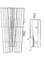
- Figure 1 is a schematic plan illustration of a railway track arrangement 1, incorporating a welded crossing vee according to the invention.
- Figure 2 illustrates a centre bar of the crossing, in which a nose is formed at one end which has its entire surface constituted by the weld material.
- the crossing or frog 1 shown in Figure 1 is a fixed or "common crossing”.
- the nose of a welded railway crossing is formed by arranging a pair of rails side-by-side so as to define a gap therebetween which extends longitudinally of the rails and throughout the height of the rails between the upper and lower surfaces thereof.
- a spacer plate is arranged in the gap so as to define spaces above and below the upper and lower edges of the plate, and weld material is deposited into these spaces to such an extent that the material when hardened, is substantially flush with the upper and lower surfaces of the rails.
- the weld material which is used ⁇ is carefully selected to be harder and more durable than the material from which the rails are made.
- a crossing nose is formed at one end of the pair of rails by machining of the upper edges of the rails at this end to such an extent that the surface of the nose is constituted solely by weld material.
- weld material is that obtained from 5%Cr 1 ⁇ 2%Mo type welding wire (A34) which provides an increased hardness above 330 HV with Grade A rail.
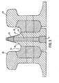
- FIG. 3 there is shown the manner of formation of the nose of the crossing.
- a pair of rails 10 and 11 are arranged side-by-side and define a longitudinal gap therebetween in which a longitudinal spacer plate 12 is positioned.
- the spacer plate defines spaces 13 and 14 above and below the upper and lower edges thereof, and weld material fills these spaces to such an extent as to be substantially flush with the upper and lower surfaces of the rails.
- a crossing nose is formed at one end of the pair of rails 10 and 11, by machining of the upper edges of the rails at this end to such an extent that the surface of the nose is constituted solely by the weld material, which is harder and more durable than the material from which the rails are formed.
- Figure 2 illustrates in more detail the manner by which the nose is formed at the end of the pair of rails.
- weld material deposited in the space above the upper edge of the spacer plate 12 is shown at 15 , and subsequently the contour of the nose is formed by machining-away of the upper edges of the rails and partly through the weld material 15, along the contour line 16.
- FIG. 4 there is shown the formation of an extended nose for the crossing, which is obtained by providing a spacer plate which is reduced in height, relative to the remainder of the plate, in the region of the nose of the crossing.
- This reduction in height of the spacer plate allows a greater volume of weld material to be deposited at the nose end, thereby increasing the strength of the nose construction.
- the finished profile of the nose is shown by dashed line 17 in Figure 5, which is formed by machining through the head 18 of a rail indicated generally by reference numeral 19 having a web 20 and a foot 21.
- the foot of the wing rail is made to conform to the shape of the Vee foot, either by running-out, or shaping round the nose.
- At least the nose extended region of the crossing may be formed by weld material which is built- up with suitable weld material such as Tensitrode 550 (ESAB) , or Migweld A33, prior to electro-slag welding.
- suitable weld material such as Tensitrode 550 (ESAB) , or Migweld A33, prior to electro-slag welding.
- the crossing is illustrated arranged between two adjacent rails 22 and 23 which are securely fastened to the nose with machinable blocks 24 and 25 positioned between these rails and the nose.
- a welded crossing vee to be used in a fixed crossing (as shown in Figure 1)
- the invention also includes a movable or "swing nose” crossing which is provided with a welded crossing vee, generally similar to that described above and illustrated in Figures 2 to 5.
- the profile of the nose of the welded crossing vee will be altered, to suit the requirements of a swing nose crossing.
- FIG. 6 There is shown schematically in Figure 6 a swing nose crossing in which the welded crossing vee will be provided.
- the crossing is designated generally by reference 26, and comprises a swing nose 27 which is movable between a "through road” position shown in full lines in Figure 6 to a "turnout road” position shown in dotted lines.
- the nose portion 28 of the swing nose comprises a welded crossing vee according to the invention, and is constructed generally similarly to that described above with reference to Figures 2 to 5 for a fixed crossing.
- the nose portion 28 is formed by a pair of rails arranged side-by-side so as to form a gap therebetween which extends generally longitudinally of the rails and throughout the height of the rails between the upper and lower surfaces thereof, a spacer plate arranged in the gap so as to define spaces above and below the upper and lower edges of the plate, and weld material which is harder and more durable than the material of the-rail and which fills the spaces so as to be substantially flush with the upper and lower surfaces of the rails.
- a nose is then formed which has its rail wheel engaging surface constituted solely by the (harder and more durable) weld material, by machining the upper edges of the rails and into the weld material until the desired profile for a swing-nose is obtained.
- the crossing has a usual sliding vee joint 29, and flexing point 30.
Applications Claiming Priority (2)
| Application Number | Priority Date | Filing Date | Title |
|---|---|---|---|
| GB8234214 | 1982-12-01 | ||
| GB08234214A GB2131070B (en) | 1982-12-01 | 1982-12-01 | Welded railway crossing |
Publications (1)
| Publication Number | Publication Date |
|---|---|
| EP0112063A1 true EP0112063A1 (de) | 1984-06-27 |
Family
ID=10534650
Family Applications (1)
| Application Number | Title | Priority Date | Filing Date |
|---|---|---|---|
| EP83307057A Ceased EP0112063A1 (de) | 1982-12-01 | 1983-11-18 | Geschweisstes Herzstück |
Country Status (4)
| Country | Link |
|---|---|
| EP (1) | EP0112063A1 (de) |
| AU (1) | AU2168483A (de) |
| GB (1) | GB2131070B (de) |
| IN (1) | IN161934B (de) |
Cited By (2)
| Publication number | Priority date | Publication date | Assignee | Title |
|---|---|---|---|---|
| WO2002099194A1 (de) * | 2001-06-05 | 2002-12-12 | Josch Strahlschweisstechnik Gmbh | Herzstück für weichen und verfahren zu seiner herstellung |
| CN106812033A (zh) * | 2017-02-21 | 2017-06-09 | 四川建筑职业技术学院 | 一种基于北斗系统的新型道岔系统 |
Families Citing this family (1)
| Publication number | Priority date | Publication date | Assignee | Title |
|---|---|---|---|---|
| GB2284001B (en) * | 1993-11-18 | 1997-10-08 | Bicc Plc | Improvements relating to railway track switches |
Citations (4)
| Publication number | Priority date | Publication date | Assignee | Title |
|---|---|---|---|---|
| FR670932A (fr) * | 1928-07-05 | 1929-12-06 | Croisement de voies | |
| DE512791C (de) * | 1928-10-20 | 1930-11-18 | Ver Stahlwerke Akt Ges | Aus Vignolschienen zusammengesetztes Herzstueck |
| DE1145654B (de) * | 1961-04-01 | 1963-03-21 | Deutschland Ag Maschf | Einfaches Herzstueck |
| AT343712B (de) * | 1976-05-18 | 1978-06-12 | Voest Ag | Verfahren zur verbindung von aus austenitischem mangan-stahl-guss bestehenden herzstucken mit aus kohlenstoffstahl bestehenden schienen unter vermittlung eines zwischenstuckes durch schweissung |
Family Cites Families (1)
| Publication number | Priority date | Publication date | Assignee | Title |
|---|---|---|---|---|
| GB328528A (en) * | 1928-10-19 | 1930-05-01 | Ver Stahlwerke Ag | Improvements in and relating to wearproof insertions for crossings and points with vignoles rails |
-
1982
- 1982-12-01 GB GB08234214A patent/GB2131070B/en not_active Expired
-
1983
- 1983-11-18 EP EP83307057A patent/EP0112063A1/de not_active Ceased
- 1983-11-25 AU AU21684/83A patent/AU2168483A/en not_active Abandoned
- 1983-11-30 IN IN1469/CAL/83A patent/IN161934B/en unknown
Patent Citations (4)
| Publication number | Priority date | Publication date | Assignee | Title |
|---|---|---|---|---|
| FR670932A (fr) * | 1928-07-05 | 1929-12-06 | Croisement de voies | |
| DE512791C (de) * | 1928-10-20 | 1930-11-18 | Ver Stahlwerke Akt Ges | Aus Vignolschienen zusammengesetztes Herzstueck |
| DE1145654B (de) * | 1961-04-01 | 1963-03-21 | Deutschland Ag Maschf | Einfaches Herzstueck |
| AT343712B (de) * | 1976-05-18 | 1978-06-12 | Voest Ag | Verfahren zur verbindung von aus austenitischem mangan-stahl-guss bestehenden herzstucken mit aus kohlenstoffstahl bestehenden schienen unter vermittlung eines zwischenstuckes durch schweissung |
Cited By (2)
| Publication number | Priority date | Publication date | Assignee | Title |
|---|---|---|---|---|
| WO2002099194A1 (de) * | 2001-06-05 | 2002-12-12 | Josch Strahlschweisstechnik Gmbh | Herzstück für weichen und verfahren zu seiner herstellung |
| CN106812033A (zh) * | 2017-02-21 | 2017-06-09 | 四川建筑职业技术学院 | 一种基于北斗系统的新型道岔系统 |
Also Published As
| Publication number | Publication date |
|---|---|
| IN161934B (de) | 1988-02-27 |
| GB2131070B (en) | 1986-01-15 |
| GB2131070A (en) | 1984-06-13 |
| AU2168483A (en) | 1984-06-07 |
Similar Documents
| Publication | Publication Date | Title |
|---|---|---|
| CA1323013C (en) | Railway switch comprising a frog having a movable main point and auxiliary point | |
| EP0112063A1 (de) | Geschweisstes Herzstück | |
| US20070007394A1 (en) | System, method, and apparatus for railroad turnout and derail lift frog | |
| KR100705337B1 (ko) | 철도 분기기용 용접 크로싱 및 그의 제조방법 | |
| US4362282A (en) | Railroad frogs | |
| US1640204A (en) | Railroad switching device | |
| US5393019A (en) | Railroad turnout frog with continuous running surface | |
| US5312075A (en) | Railroad frog | |
| EP2240642B1 (de) | Bewegliches weichenherzstück | |
| KR200402755Y1 (ko) | 철도 분기기용 용접 크로싱 | |
| EP1555347B1 (de) | Eisenbahnweiche mit flexibler Zunge | |
| US902589A (en) | Railway-frog. | |
| US792365A (en) | Railway-crossing. | |
| US530197A (en) | Railway-crossing | |
| US20240110339A1 (en) | Frog, and method for producing wing rails for a frog | |
| US2148940A (en) | Reinforced crossing of lines | |
| SU1204655A1 (ru) | Стрелочный перевод крутой марки,преимущественно дл технологических путей промышленных предпри тий | |
| KR200354598Y1 (ko) | 시저스 분기기 | |
| DD223480A1 (de) | Flachrillenherzstueck und -kreuzungsstueck | |
| US812794A (en) | Movable-point railway-crossing. | |
| KR101792691B1 (ko) | 분기기 크로싱의 윙레일 구조물 | |
| US3378683A (en) | Cast-steel railway crossing pieces | |
| US1808389A (en) | Frog for grooved rails | |
| US2686026A (en) | Switch heel block | |
| US536734A (en) | Railway-switch work |
Legal Events
| Date | Code | Title | Description |
|---|---|---|---|
| PUAI | Public reference made under article 153(3) epc to a published international application that has entered the european phase |
Free format text: ORIGINAL CODE: 0009012 |
|
| AK | Designated contracting states |
Designated state(s): AT BE CH DE FR GB IT LI LU NL SE |
|
| 17P | Request for examination filed |
Effective date: 19840830 |
|
| STAA | Information on the status of an ep patent application or granted ep patent |
Free format text: STATUS: THE APPLICATION HAS BEEN REFUSED |
|
| 18R | Application refused |
Effective date: 19860128 |
|
| RIN1 | Information on inventor provided before grant (corrected) |
Inventor name: COMPTON, KENNETH WILLIAM Inventor name: BROWN, IVAN HAROLD Inventor name: ADAMS, DONALD VERNON |