EP0111067A1 - Conical screw mixer - Google Patents
Conical screw mixer Download PDFInfo
- Publication number
- EP0111067A1 EP0111067A1 EP83109054A EP83109054A EP0111067A1 EP 0111067 A1 EP0111067 A1 EP 0111067A1 EP 83109054 A EP83109054 A EP 83109054A EP 83109054 A EP83109054 A EP 83109054A EP 0111067 A1 EP0111067 A1 EP 0111067A1
- Authority
- EP
- European Patent Office
- Prior art keywords
- sealing
- flange
- screw mixer
- bell
- mixer according
- Prior art date
- Legal status (The legal status is an assumption and is not a legal conclusion. Google has not performed a legal analysis and makes no representation as to the accuracy of the status listed.)
- Granted
Links
Images


Classifications
-
- B—PERFORMING OPERATIONS; TRANSPORTING
- B01—PHYSICAL OR CHEMICAL PROCESSES OR APPARATUS IN GENERAL
- B01F—MIXING, e.g. DISSOLVING, EMULSIFYING OR DISPERSING
- B01F27/00—Mixers with rotary stirring devices in fixed receptacles; Kneaders
- B01F27/80—Mixers with rotary stirring devices in fixed receptacles; Kneaders with stirrers rotating about a substantially vertical axis
- B01F27/95—Mixers with rotary stirring devices in fixed receptacles; Kneaders with stirrers rotating about a substantially vertical axis with stirrers having planetary motion, i.e. rotating about their own axis and about a sun axis
- B01F27/953—Mixers with rotary stirring devices in fixed receptacles; Kneaders with stirrers rotating about a substantially vertical axis with stirrers having planetary motion, i.e. rotating about their own axis and about a sun axis using only helical stirrers
-
- B—PERFORMING OPERATIONS; TRANSPORTING
- B01—PHYSICAL OR CHEMICAL PROCESSES OR APPARATUS IN GENERAL
- B01F—MIXING, e.g. DISSOLVING, EMULSIFYING OR DISPERSING
- B01F35/00—Accessories for mixers; Auxiliary operations or auxiliary devices; Parts or details of general application
- B01F35/40—Mounting or supporting mixing devices or receptacles; Clamping or holding arrangements therefor
- B01F35/41—Mounting or supporting stirrer shafts or stirrer units on receptacles
- B01F35/412—Mounting or supporting stirrer shafts or stirrer units on receptacles by supporting both extremities of the shaft
- B01F35/4121—Mounting or supporting stirrer shafts or stirrer units on receptacles by supporting both extremities of the shaft at the top and at the bottom of the receptacle, e.g. for performing a conical orbital movement about a vertical axis
-
- B—PERFORMING OPERATIONS; TRANSPORTING
- B01—PHYSICAL OR CHEMICAL PROCESSES OR APPARATUS IN GENERAL
- B01F—MIXING, e.g. DISSOLVING, EMULSIFYING OR DISPERSING
- B01F35/00—Accessories for mixers; Auxiliary operations or auxiliary devices; Parts or details of general application
- B01F35/30—Driving arrangements; Transmissions; Couplings; Brakes
- B01F2035/35—Use of other general mechanical engineering elements in mixing devices
- B01F2035/352—Bearings
-
- B—PERFORMING OPERATIONS; TRANSPORTING
- B01—PHYSICAL OR CHEMICAL PROCESSES OR APPARATUS IN GENERAL
- B01F—MIXING, e.g. DISSOLVING, EMULSIFYING OR DISPERSING
- B01F27/00—Mixers with rotary stirring devices in fixed receptacles; Kneaders
- B01F27/05—Stirrers
- B01F27/11—Stirrers characterised by the configuration of the stirrers
- B01F27/114—Helically shaped stirrers, i.e. stirrers comprising a helically shaped band or helically shaped band sections
- B01F27/1143—Helically shaped stirrers, i.e. stirrers comprising a helically shaped band or helically shaped band sections screw-shaped, e.g. worms
-
- B—PERFORMING OPERATIONS; TRANSPORTING
- B01—PHYSICAL OR CHEMICAL PROCESSES OR APPARATUS IN GENERAL
- B01F—MIXING, e.g. DISSOLVING, EMULSIFYING OR DISPERSING
- B01F27/00—Mixers with rotary stirring devices in fixed receptacles; Kneaders
- B01F27/23—Mixers with rotary stirring devices in fixed receptacles; Kneaders characterised by the orientation or disposition of the rotor axis
- B01F27/232—Mixers with rotary stirring devices in fixed receptacles; Kneaders characterised by the orientation or disposition of the rotor axis with two or more rotation axes
- B01F27/2324—Mixers with rotary stirring devices in fixed receptacles; Kneaders characterised by the orientation or disposition of the rotor axis with two or more rotation axes planetary
-
- B—PERFORMING OPERATIONS; TRANSPORTING
- B01—PHYSICAL OR CHEMICAL PROCESSES OR APPARATUS IN GENERAL
- B01F—MIXING, e.g. DISSOLVING, EMULSIFYING OR DISPERSING
- B01F27/00—Mixers with rotary stirring devices in fixed receptacles; Kneaders
- B01F27/60—Mixers with rotary stirring devices in fixed receptacles; Kneaders with stirrers rotating about a horizontal or inclined axis
- B01F27/61—Mixers with rotary stirring devices in fixed receptacles; Kneaders with stirrers rotating about a horizontal or inclined axis about an inclined axis
Definitions
- the invention relates to a cone screw mixer according to the preamble of claim 1.
- Kohus screw mixer An initially mentioned Kohus screw mixer is used for mixing and processing powdery, liquid or pasty liquids in chemical process engineering, in the food industry and in related industries.
- the mixing screw arranged in the interior rotates around the longitudinal axis and is moved parallel to the inner wall in the product space.
- This requires a torsionally rigid, angularly movable coupling in the floor area, which transmits both the rotation of the mixing screw and the swiveling movement of the mixing screw along the inner wall in the product space to a fixed bearing.
- a universal joint for this purpose as a torsionally rigid compensating coupling
- the previously known conical screw mixers arranging the universal joint directly in the product space. The universal joint was protected against ingress of products with a bellows.
- the storage of a torsionally rigid compensating coupling (especially universal joint) directly in the product space is disadvantageous because the compensating coupling is difficult to access for maintenance. If the bellows was damaged, there was a risk that the contents of the container would come into contact with the exposed universal joint and thus become dirty. In addition, it was not possible to monitor the function of such a known universal joint.
- the arrangement of a universal joint in the interior of the product space has the further disadvantage that dirt and bacteria corners form, which has an adverse effect on the product to be processed in the container.
- the mixing container with a universal joint arranged in it had to be built relatively large in order to accommodate the entire lower bearing.
- the invention has set itself the task of developing a cone screw mixer of the type mentioned in such a way that its bottom-side, torsionally rigid t angular coupling no longer offers any risk of contact with the product content and that the entire arrangement is constructed in a considerably simpler and more reliable manner.
- the invention is characterized in that the angularly movable coupling is arranged outside the product space of the mixing container below the mixing container.
- an angularly movable coupling is arranged outside and below the mixing container. Only in a preferred embodiment is this angular coupling used as a universal joint, other designs of angular couplings being possible and falling within the scope of the present invention (for example homokinetic couplings and the like). According to the subject matter of claim 2, it is preferred in this case if the angularly movable coupling is designed as a universal joint, the rotatable and pivotable part of the universal joint reaching into the product space being sealingly overlapped by a sealing bell, on the outer circumference of which a fixed sealing flange lies sealingly .
- the bottom region of the mixing container is formed by a container flange welded to the side walls, on the inside of which the sealing flange is fastened, the sealing flange having a central recess in which the sealing bell is mounted .
- an automatic adjustment of the seal between the sealing bell and sealing flange is created in that the sealing flange on its outer circumference on the inner circumference of a control flange is arranged, the adjusting flange by means of spring-loaded adjusting screws, the sealing flange to the sealing surfaces of the sealing bell pressed.
- a special version of the sealing flange is claimed according to the subject matter of claim 5, and has the advantage that the product medium possibly from the product space between the sealing bell and the sealing flange is stripped again at the sealing points, thus creating a kind of labyrinth.
- the embodiment of the sealing surface with flushing rings specified in claim 6 has the advantage that cleaning of the sealing bell or the fixed sealing flange is possible without dismantling the bearing. Furthermore, these flushing rings can be used as cooling for the sealing bell. If an optimal seal is required, there is the possibility of filling the flushing ring with pressurized sealing liquid.
- the bearing proposed according to the invention can be used universally and also enables use at higher temperatures.
- the air space between the fixed sealing flange and the sealing bell and the bearing housing also acts as an insulating layer.
- the universal joint and the sealing bell can be flushed from the inside with sealing liquid or cooling liquid or a gas. For this purpose, a connection is made for the inlet and outlet of the coolant in the bearing cover.
- the shaft or mixing screw is connected by an internal thread to the screw-in bolt or the complete bearing via a coupling piece, no screws or other connecting elements are contained in the product area. This enables a design without dirt and bacteria corners, which is required for the pharmaceutical and food industry. If a mixing screw is used, it can be pulled down to the bottom of the container (container flange) and ensures that a mixer is designed without lower dead spaces for the mixed product.
- the fulcrum of the shaft or mixing screw is located outside the mixing container.
- the stationary sealing flange with the adjusting flange can be made so large that the mixing screw can be introduced into the mixing container from below through the container-side flange.
- a one-piece construction of the mixing container without an intermediate flange is thus made possible. This has considerable advantages in the design of the container and also enables the mixing container to be designed economically (claim 8).
- the drive of the mixing screw from below also has advantages with regard to the container size.
- the mixing container space can be much smaller with the same usable content in the outer dimensions because the use of space-consuming bevel gear angular gears is not required. This enables a smaller design of the mixing container with the same usable space - compared to known mixing containers.
- a mixing screw 70 is arranged in a mixing container 88 which tapers conically towards the bottom region and which rotates about the axis 110 at the speed n 1 and which rotates about the container axis 100 at the speed n 2 .
- the mixing screw 70 is arranged in its upper region at the free end of a guide arm 71 which is driven at a speed n 2 by a motor 95 and a gear 72.
- Corresponding seals 73 are provided on the container lid in order to prevent the product medium from escaping from the product space 80.
- the bottom-side mounting of the mixing screw 70 takes place in the manner proposed in FIGS. 1 to 5 with the aid of a universal joint 27, the mixing screw receiving its rotary drive (drive about the axis 110) via an articulated shaft 34 which is mounted in the hollow shaft 32 the end of which is flanged to a lantern 62, at the lower end of which the geared motor 65 is attached.
- the mixing screw 70 is firmly welded to a coupling piece 29 with an internal thread.
- a screw-in bolt 1 is screwed in such a way that the thread automatically tightens during operation; ie depending on the direction of rotation of the mixer worm 70 a right or left hand thread is used.
- a rotationally fixed connection of the coupling piece 29 and screw-in bolt 1 can also be carried out with a feather key connection or a shear pin.
- a bushing 2 is mounted on the screw-in bolt 1.
- the roller bearing 6 and the bushing 7 are attached to the screw bolt 1 without play by means of the circlip 8.
- the screw-in bolt 1 is connected in a rotationally fixed manner to the upper part of the universal joint 27 by means of screws 25.
- the lower universal joint part is in turn screwed with screws 28 to the drive shaft 34 in a rotationally fixed manner.
- a sealing bell 4 with recessed seals 3 is pushed over the screw-in bolt 1 with the bushing 2, the roller bearing 6, the bushing 7 and the circlip 8 and over the universal joint 27 and secured axially and radially by means of a flange 10 with a seal 9 and washers 5. Sealing takes place via the O-ring 56.
- the screw connection is carried out using the screws 59.
- the bearings are relubricated using the blind screw 12 of the sealing washer 13.
- An additional sealing is ensured via the O-ring 11.
- the construction and assembly must ensure that the center of the universal joint 27 and the center of the sealing bell 4 are one and the same point.
- the mixing screw shaft can be inclined up to 25 ° to the vertical axis.
- a bushing 31 (shaft sleeve) is rotatably mounted on the cardan shaft 34. Furthermore, the Bearing inner rings of the bearings 36 and the tube 33 are mounted on the drive shaft 34 and secured with the circlip 38.
- the cardan shaft 34 is provided with different centerings for the bearings and a threaded pin 46 with a square.
- the bearing housing consists of a tubular housing 18, a counter flange 52 and a hollow shaft 32, which are welded together.
- a plurality of assembly and control openings are arranged in the tubular housing 18 and are closed by a plurality of covers 21, the screws 60 and the sealing rings 19 arranged on the circumference of the bearing housing.
- the outer rings of the bearing 36 are inserted into the hollow shaft 32 and are secured with the circlips 37 against axial displacement.
- the bearing flange 43 and the double-acting axial bearing 40 are inserted into the hollow shaft 32.
- the bearing flange 43 with the O-ring 42 is now pushed into the bore of the hollow shaft 32 or over the outer ring of the bearing 40 and firmly connected to the hollow shaft 32 with the screws 60.
- the bearing flange 39 must be in contact with the circlip 37 and the axial bearing 40 must be set axially with almost no play. Furthermore, the shaft sealing ring 30 and the lubricating nipple 58 are pressed into the hollow shaft 32.
- the propeller shaft 34 is then inserted.
- the drive shaft 34 is firmly connected to the thrust bearing 40 by means of the clamping disk 41, the spring ring 47 and the threaded nut 48.
- connection of the mixing screw 70 to the screw-in bolt 1 is carried out by turning the square of the drive shaft 34, the coupling piece 29 screwed onto the thread of the screw bolt 1. This can be done without disassembling the bearing assembly. After performing this work, the bearing flange 43 is closed with the cover 45, the O-ring 44 and the screws 61.
- the bearing housing is screwed to the container flange 17 in a rotationally fixed manner by means of threaded bolts 55, nuts 54 and spring washers 53 and sealed with an O-ring 26.
- the sealing between the sealing bell 4 and the container flange 17 is carried out with a sealing flange 14, an adjusting flange 17 with an 0-ring 16.
- the material of the sealing flange 14 can be made of Teflon (registered trademark for DuPont) or another equal bearing material.
- the material of the sealing bell 4 must be made of a hardened, plated or stainless steel material or another material that matches the sealing flange 14.
- the sealing flange 14 has an inner flushing ring 49 which is provided with an inlet or outlet bore which is drilled through the adjusting ring 15. 3 shows that the inlet or outlet 75, 76 attaches to the bearing housing above the cover 21.
- the inlet and outlet bores of the adjusting and sealing flange 14, 15 are at the same location as the inlet and outlet bores in the container flange 17.
- the adjusting flange 15 is secured against rotation with a screw bolt 20 with a lock nut.
- the adjusting flange 15 there are several spring-loaded preload screws 24 with lock nuts 23 and the springs 22 attached. These preload screws 24 press the adjusting flange 15 with the sealing flange 14 downwards against the sealing surface of the sealing bell 4.
- the frictional forces between the sealing bell 4 and the sealing flange 14 must be greater than the frictional forces caused by the roller bearings 6 and by the seals 3 and 9. This ensures that the mixing screw 70 rotates in the sealing bell 4 and thus the sealing bell 4 only performs a tilting movement corresponding to the speed n 2 .
- FIG. 5 shows a special version of the bearing according to the invention.
- the propeller shaft 34 is provided with a longer stub shaft in which the key 66 is embedded.
- the propeller shaft 34 is axially secured to the bearing 40 by a threaded nut 67.
- a lantern 62 is screwed onto the connecting flange 43, and a geared motor 65 is mounted on the other side.
- the torque entrainment from the geared motor 65 to the cardan shaft 34 is carried out via the key 64 and the coupling 63.
- the mixing screw 70 can be driven from below via the drive shaft 34, the universal joint 27 and the screw-in bolt 1.
- FIG. 7 shows a special version of the mixing worm drive from below, a sprocket 120 being rotatably mounted on the cardan shaft 34.
- a motor mounting flange 121 is attached to the hollow shaft 32.
- the hollow shaft geared motor 122 is connected to the motor mounting flange 121 with an intermediate flange 123 with screws 124.
- a drive shaft 125 with a mounted sprocket is non-rotatably attached.
- the power transmission from the sprocket 126 to the cardan shaft 34 is carried out with a chain 127.
- the requirement for the drive from below is again schematically explained in FIG. 6. It is essential that the mixing screw 70 is driven from below and guided in the guide arm 71 at the top.
- This guide arm 71 is rotatably connected to a gear motor 72.
- the seal 73 can be carried out by a stuffing box, a mechanical seal or another sealing element.
- the rotary movement of the mixing screw 70 is effected by the lower gear motor 65 and the pivoting movement of the mixing screw by the upper gear motor 95, 72.
- a special design of the sealing flange 84 is created in that a plurality of grooves 85, 86, 87 are provided in parallel at a distance from one another on the inner circumference of the sealing flange 84. A possibly penetrating product medium is stripped off at the sealing points and an increased seal is achieved.
- the flushing ring 49 shown in FIGS. 1 and 3 enables the sealing bell 4 or the sealing flange 14 to be cleaned without dismantling the bearing. Furthermore, this flushing ring 49 can be used as cooling for the sealing bell 4.
- the air space 74 between the sealing flange 14 and the sealing bell 4 and the bearing housing 18, 52, 32 can be regarded as an insulating layer.
- the universal joint 27 and the sealing ball parts can be flushed from the inside with sealing liquid or cooling liquid or a gas. In this case, a connection for the inlet and outlet 75, 76 of the coolant in the cover 21 is made.
- pressure relief is provided in the product room 80 and in the storage room 81 different pressures may occur.
- pressure equalization can be carried out between the product space 80 and the storage space 81.
- pressure relief of the sealing flange 14 can be made in that
- the product space 80 is connected to the flushing ring 49 through the pressure relief line 82. If only the storage space 81 is to be relieved of pressure, and thus also the seals 3, then, according to FIG. 4, the second pressure relief line 83 must be used to relieve the pressure. An optimal pressure relief is achieved by a combination of these two pressure relief lines 82, 83 according to FIG. 4.
- the lower bearing block (bearing housing) can also be provided with a cooling jacket.
- a lower cooling jacket 89 with the inlet 90 and the outlet 91 is provided, while the bearing housing itself is cooled by a second cooling jacket 79 with the inlet 68 and the outlet 69.
- Air or barrier or cooling liquid is fed into the storage space 74 via the inlet 77 and the outlet 78, it being possible for these lines to be arranged in the cover 21.
Abstract
Description
Die Erfindung betrifft einen Konus-Schneckenmischer nach dem Oberbegriff des Patentanspruchs 1.The invention relates to a cone screw mixer according to the preamble of claim 1.
Ein eingangs genannter Kohus-Schneckenmischer dient zur Mischung und Aufbereitung von pulverförmigen, flüssigen oder pastösen Flüssigkeiten in der chemischen Verfahrenstechnik, in der Nahrungsmittel-Industrie und in verwandten Industriezweigen.An initially mentioned Kohus screw mixer is used for mixing and processing powdery, liquid or pasty liquids in chemical process engineering, in the food industry and in related industries.
Die im Innenraum angeordnete Mischschnecke dreht sich um die Längsachse und wird parallel zur Innenwandung im Produktraum entlang bewegt. Hierzu bedarf es einer drehstarren, winkelbeweglichen Kupplung im Bodenbereich, welche sowohl die Drehung der Mischschnecke als auch die Schwenkbewegung der Mischschnecke entlang der Innenwandung im Produktraum auf ein ortsfestes Lager überträgt. Es ist bekannt, hierzu als drehstarre Ausgleichskupplung ein Kreuzgelenk zu verwenden, wobei die bisher bekannten Konus-Schneckenmischer das Kreuzgelenk unmittelbar im Produktraum anordneten. Das Kreuzgelenk war .gegen Eindringen von Produkten mit einem Faltenbalg geschützt.The mixing screw arranged in the interior rotates around the longitudinal axis and is moved parallel to the inner wall in the product space. This requires a torsionally rigid, angularly movable coupling in the floor area, which transmits both the rotation of the mixing screw and the swiveling movement of the mixing screw along the inner wall in the product space to a fixed bearing. It is known to use a universal joint for this purpose as a torsionally rigid compensating coupling, the previously known conical screw mixers arranging the universal joint directly in the product space. The universal joint was protected against ingress of products with a bellows.
Die Lagerung einer drehstarren Ausgleichskupplung (insbesondere Kreuzgelenk) unmittelbar im Produktraum ist nachteilig, denn die Ausgleichskupplung ist einer Wartung nur schwer zugänglich. Bei Beschädigung des Faltenbalges bestand die Gefahr,daß der Behälterinhalt mit dem dann freigelegten Kreuzgelenk in Berührung kam und dadurch verschmutzte. Darüberhinaus war eine Funktionsüberwachung eines solchen bekannten Kreuzgelenkes nicht möglich. Die Anordnung eines Kreuzgelenkes im Inneren des Produktraumes hat den weiteren Nachteil, daß sich Schmutz- und Bakterienecken bilden, was sich nachteilig auf das im Behälter zu verarbeitende Produkt auswirkt. Darüberhinaus mußte der Mischbehälter mit einem darin angeordneten Kreuzgelenk relativ groß gebaut werden, um das komplette untere Lager mit aufzunehmen.The storage of a torsionally rigid compensating coupling (especially universal joint) directly in the product space is disadvantageous because the compensating coupling is difficult to access for maintenance. If the bellows was damaged, there was a risk that the contents of the container would come into contact with the exposed universal joint and thus become dirty. In addition, it was not possible to monitor the function of such a known universal joint. The arrangement of a universal joint in the interior of the product space has the further disadvantage that dirt and bacteria corners form, which has an adverse effect on the product to be processed in the container. In addition, the mixing container with a universal joint arranged in it had to be built relatively large in order to accommodate the entire lower bearing.
Die Erfindung hat sich die Aufgabe gestellt, einen Konus-Schneckenmischer der eingangs genannten Art so weiterzubilden, daß seine bodenseitig angeordnete, drehstarretwinkelbewegliche Kupplung keine Berührungsgefahr mehr mit dem Produktinhalt bietet und daß die gesamte Anordnung wesentlich einfacher und betriebssicherer aufgebaut ist.The invention has set itself the task of developing a cone screw mixer of the type mentioned in such a way that its bottom-side, torsionally rigid t angular coupling no longer offers any risk of contact with the product content and that the entire arrangement is constructed in a considerably simpler and more reliable manner.
Zur Lösung der gestellten Aufgabe ist die Erfindung dadurch gekennzeichnet, daß die winkelbewegliche Kupplung außerhalb des Produktraumes des Mischbehälters unterhalb des Mischbehälters angeordnet ist.To achieve the object, the invention is characterized in that the angularly movable coupling is arranged outside the product space of the mixing container below the mixing container.
Bei der vorliegenden Erfindung wird in allgemeiner Form Schutz dafür beansprucht, daß eine winkelbewegliche Kupplung außerhalb und unterhalb des Mischbehälters angeordnet ist. Lediglich in einer bevorzugten Ausführungsform wird diese winkelbewegliche Kupplung als Kreuzgelenk beansprucht, wobei andere Ausführungen von winkelbeweglichen Kupplungen möglich sind und in den Schutzbereich der vorliegenden Erfindung fallen (zum Beispiel homokinetische Kupplungen und dergleichen). Nach dem Gegenstand des Anspruches 2 wird es hierbei bevorzugt, wenn die winkelbewegliche Kupplung als Kreuzgelenk so ausgebildet ist, wobei der in den Produktraum greifende, dreh- und schwenkbare Teil des Kreuzgelenkes von einer Dichtungsglocke abdichtend übergriffen ist, an deren Außenumfang abdichtend ein ortsfester Dichtflansch anliegt.In the present invention, protection is claimed in general terms that an angularly movable coupling is arranged outside and below the mixing container. Only in a preferred embodiment is this angular coupling used as a universal joint, other designs of angular couplings being possible and falling within the scope of the present invention (for example homokinetic couplings and the like). According to the subject matter of
Es werden also nach dem Gegenstand des Anspruches 2 feste Dichtflächen vorgeschlagen, die nicht mehr einer derartigen Beschädigungsgefahr ausgesetzt sind, wie der vorher erwähnte Faltenbalg. Durch die Anordnung einer halbkugeligen Dichtungsglocke in Verbindung mit einem abdichtend daran anliegenden Dichtflansch wird der wesentliche Vorteil erreicht, daß sowohl die drehende als auch die schwenkende Bewegung des beweglichen Teils des Kreuzgelenkes ohne besondere Probleme aufgenommen wird.So there are proposed according to the subject of
Ein besonderer Vorteil ergibt sich nach dem Gegenstand des Anspruches 3 dadurch, daß der Bodenbereich des Mischbehälters durch einen mit den Seitenwandungen verschweissten Behälterflansch gebildet wird, an dessen Innenseite der Dichtflansch befestigt ist, wobei der Dichtflansch eine zentrale Ausnehmung aufweist, in welcher die Dichtungsglocke gelagert ist. Hierdurch ergibt sich ein besonders einfacher Aufbau, wobei der ortsfeste Dichtflansch von dem Behälterflansch abgeschraubt und entfernt werden kann, so daß die gesamte bodenseitige Lagerung zusammen mit der daran befestigten Mischschnecke nach unten aus dem Mischbehälter herausgezogen werden kann. Hierdurch wird wesentliche Arbeits- und Montagezeit gespart.A particular advantage arises according to the subject matter of
Um die Lebensdauer des vorgeschlagenen Dichtsystems zu vergrößern und um dieses Dichtsystem verschiedenen Dichtaufgaben anzupassen, ist es nach dem Gegenstand des Anspruches 4 vorgesehen, daß eine selbsttätige Nachstellung der Abdichtung zwischen Dichtungsglocke und Dichtflansch dadurch geschaffen ist, daß der Dichtflansch an seinem Außenumfang am Innenumfang eines Stellflansches angeordnet ist, wobei der Stellflansch mittels federbelasteter Stellschrauben den Dichtflansch an die Dichtungsflächen der Dichtungsglocke anpresst.In order to increase the life of the proposed sealing system and to adapt this sealing system to various sealing tasks, it is provided according to the subject matter of
Hierdurch wird eine kraftschlüssige Anlage des Dichtflansches an der Dichtungsglocke geschaffen, die sich automatisch nachstellt. Entsprechend dem Verschleiß von Dichtungsglocke und Dichtflansch erfolgt hiermit immer ein gleichmässiger Andruck der beiden genannten Teile aneinander.This creates a frictional contact between the sealing flange and the sealing bell, which adjusts itself automatically. Depending on the wear of the sealing bell and sealing flange, the two parts mentioned are always pressed evenly against each other.
Ebenso werden hierdurch Dichtprobleme bei Wärmedehnungen vermieden, weil die federbelastete Vorspannung des ortsfesten Dichtflansches auch nachgibt und so Wärmedehnungen ausgleicht.This also avoids sealing problems in the case of thermal expansion because the spring-loaded preload of the fixed sealing flange also yields and thus compensates for thermal expansion.
Eine Sonderausführung des Dichtflansches wird nach dem Gegenstand des Anspruches 5 beansprucht, und hat den Vorteil, daß das evtl. vom Produktraum zwischen der Dichtungsglocke und dem Dichtflansch gelangende Produktmedium jeweils wieder an den Dichtstellen abgestreift wird und somit eine Art Labyrinth geschaffen wird.A special version of the sealing flange is claimed according to the subject matter of
Die im Anspruch 6 angegebene Ausführung der Dichtungsfläche mit Spülringen hat den Vorteil, daß eine Reinigung der Dichtungsglocke bzw. des ortsfesten Dichtflansches ohne Demontage der Lagerung möglich ist. Weiterhin können diese Spülringe als Kühlung für die Dichtungsglocke verwendet werden. Sollte eine optimale Abdichtung erforderlich sein, gibt_es die Möglichkeit, den Spülring mit druckbeaufschlagter Sperrflüssigkeit zu füllen.The embodiment of the sealing surface with flushing rings specified in
Da die Wellen bzw. Mischschneckenlagerung außerhalb des Behälters ist, ist das erfindungsgemäss vorgeschlagene Lager universell einsetzbar und ermöglicht auch einen Einsatz bei höheren Temperaturen. Der Luftraum zwischen dem ortsfesten Dichtflansch und der Dichtglocke und dem Lagergehäuse wirkt zugleich als Isolierschicht. Außerdem kann das Kreuzgelenk und die Dichtungsglocke von innen mit Sperrflüssigkeit bzw.Kühlflüssigkeit oder einem Gas gespült werden. Hierzu werden jeweils ein Anschluß für Ein- und Ablauf der Kühlflüssigkeit im Lagerdeckel gemacht.Since the shafts or mixing screw bearings are outside the container, the bearing proposed according to the invention can be used universally and also enables use at higher temperatures. The air space between the fixed sealing flange and the sealing bell and the bearing housing also acts as an insulating layer. In addition, the universal joint and the sealing bell can be flushed from the inside with sealing liquid or cooling liquid or a gas. For this purpose, a connection is made for the inlet and outlet of the coolant in the bearing cover.
Somit wird die Funktionstüchtigkeit auch bei sehr hohen Behältertemperaturen gewährleistet, da mittels der Sperrflüssigkeit bzw. der Kühlflüssigkeit die Lagerstellen temperaturkonstant gehalten werden können, (Anspruch 7).Thus, the functionality is ensured even at very high container temperatures, since the storage points can be kept constant in temperature by means of the barrier liquid or the cooling liquid (claim 7).
Da die Welle oder Mischschnecke durch ein Innengewinde mit dem Einschraubbolzen bzw. der kompletten Lagerung über ein Kupplungsstück verbunden ist, sind im Produktraum keine Schrauben oder andere Verbindungselemente mehr enthalten. Dies ermöglicht eine für die Pharma-und Lebensmittel-Industrie erforderliche Ausführung ohne Schmutz- und Bakterienecken. Sollte eine Mischschnecke eingesetzt werden, so ist diese bis auf den Behälterboden (Behälterflansch) herabziehbar und gewährleistet eine Ausführung eines Mischers ohne untere Toträume für das Mischprodukt.Since the shaft or mixing screw is connected by an internal thread to the screw-in bolt or the complete bearing via a coupling piece, no screws or other connecting elements are contained in the product area. This enables a design without dirt and bacteria corners, which is required for the pharmaceutical and food industry. If a mixing screw is used, it can be pulled down to the bottom of the container (container flange) and ensures that a mixer is designed without lower dead spaces for the mixed product.
Der Drehpunkt der Welle oder Mischschnecke ist außerhalb des Mischbehälters angeordnet. Der ortsfeste Dichtflansch mit dem Stellflansch kann so groß ausgeführt werden, daß die Mischschnecke von unten durch den behälterseitigen Flansch in den Mischbehälter eingebracht werden kann. Bei großen konischen Mischbehältern wird somit eine einteilige Bauweise des Mischbehälters ohne Zwischenflansch ermöglicht. Dies hat erhebliche Vorteile bei der Behälterauslegung und ermöglicht außerdem eine kostengünstige Ausführung des Mischbehälters, (Anspruch 8).The fulcrum of the shaft or mixing screw is located outside the mixing container. The stationary sealing flange with the adjusting flange can be made so large that the mixing screw can be introduced into the mixing container from below through the container-side flange. In the case of large conical mixing containers, a one-piece construction of the mixing container without an intermediate flange is thus made possible. This has considerable advantages in the design of the container and also enables the mixing container to be designed economically (claim 8).
Im Produktraum und im Lagerraum treten ggf. verschiedene Drücke auf. Um die Dichtungen der Dichtglocke am anliegenden Teil des Kreuzgelenkes sowie den Dichtflansch von diesen zusätzlichen Druckbelastungen zu entlasten, kann ein Druckausgleich zwischen dem Produktraum und dem Lagerraum durchgeführt werden. Hierbei gibt es verschiedene Möglichkeiten:
- Zum ersten kann eine Druckentlastung des Dichtringes gemacht werden, indem der Produktraum mit dem Spülring durch eine erste Druckentlastungsleitung verbunden wird. Soll nur der Lagerraum druckentlastet werden, und damit auch die Dichtringe zwischen Dichtglocke und dem beweglichen Teil des Kreuzgelenkes, so muß eine Druckentlastung mit einer zweiten Druckentlastungsleitung durchgeführt werden. Eine optimale Druckentlastung wird durch eine Kombination dieser beiden Druckentlastungsleitungen erreicht. Dies hat zur Folge, daß die produktberührenden Dichtringe wesentlich höhere Standzeiten haben. Sollte eine derartige Druckentlastung bei höheren Betriebstemperaturen durchgeführt werden, kann der untere Lagerblock zusätzlich mit einem Doppelmantel gekühlt werden, (
Anspruch 9, Anspruch 10).
- First of all, pressure relief of the sealing ring can be made by connecting the product space to the flushing ring through a first pressure relief line. If only the storage space is to be relieved of pressure, and thus also the sealing rings between the sealing bell and the movable part of the universal joint, pressure relief must be carried out with a second pressure relief line. Optimal pressure relief is achieved by a combination of these two pressure relief lines. As a result, the sealing rings in contact with the product have a significantly longer service life. Should such pressure relief be carried out at higher operating temperatures, the lower bearing block can additionally be cooled with a double jacket (
claim 9, claim 10).
Durch die Tatsache, daß das Kreuzgelenk außerhalb und unterhalb des Mischbehälters angeordnet ist, ergibt sich der weitere wesentliche Vorteil, daß der Drehantrieb der Mischschnecke durch einen unten am Kreuzgelenk angeflanschten Getriebemotor erfolgen kann, (Anspruch. 11). Durch den Antrieb der Mischschnecke von unten kann speziell bei Konus-Schneckenmischern auf aufwendige und kostspielige Kegelradgetriebe verzichtet werden. Es ist lediglich ein starrer Führungsarm erforderlich, welcher die Mischschnecke führt.The fact that the universal joint is arranged outside and below the mixing container results in the further essential advantage that the rotary drive of the mixing screw can be carried out by means of a geared motor flanged at the bottom of the universal joint (claim 11). By driving the mixing screw from below, complex and costly bevel gearboxes can be dispensed with, especially for cone screw mixers. All that is required is a rigid guide arm that guides the mixing screw.
Der Antrieb der Mischschnecke von unten hat auch hinsichtlich der Behältergröße Vorteile. Der Mischbehälterraum kann bei gleichem Nutzinhalt wesentlich kleiner in den Außenabmessungen gebaut werden, weil der Einsatz von raumgreifenden Kegelrad-Winkelgetrieben entfällt. Somit wird eine kleinere Bauweise des Mischbehälters bei gleichem Nutzraum - im Vergleich zu bekannten Mischbehältern - möglich.The drive of the mixing screw from below also has advantages with regard to the container size. The mixing container space can be much smaller with the same usable content in the outer dimensions because the use of space-consuming bevel gear angular gears is not required. This enables a smaller design of the mixing container with the same usable space - compared to known mixing containers.
Der Erfindungsgegenstand der vorliegenden Erfindung ergibt sich nicht nur aus dem Gegenstand der einzelnen Patentansprüche, sondern auch aus der Kombination der einzelnen Patentansprüche untereinander.The subject matter of the present invention results not only from the subject matter of the individual patent claims, but also from the combination of the individual patent claims with one another.
Alle in den Unterlagen offenbarten Angaben und Merkmale, insbesondere die in den Zeichnungen dargestellte, räumliche Ausbildung werden als erfindungswesentlich beansprucht, soweit sie einzeln oder in Kombination gegenüber dem Stand der Technik neu sind.All of the information and features disclosed in the documents, in particular the spatial design shown in the drawings, are claimed to be essential to the invention insofar as they are new to the prior art, individually or in combination.
Im folgenden wird die Erfindung anhand von lediglich einen Ausführungsweg darstellenden Zeichnungen näher erläutert. Hierbei gehen aus den Zeichnungen und ihrer Beschreibung weitere erfindungswesentliche Vorteile und Merkmale der Erfindung hervor.The invention is explained in more detail below with the aid of drawings which illustrate only one embodiment. Further advantages and features of the invention which are essential to the invention emerge from the drawings and their description.
Es zeigen:
- Figur 1: Vertikalschnitt durch die bodenseitige Lagerung der Mischschnecke in einem Konus-Schneckenmischer;
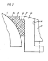
- Figur 2: vergrößerte Teildarstellung der Abdichtung zwischen Dichtungsglocke und ortsfestem Dichtungsflansch in einem gegenüber.Figur 1 geänderten Ausführungsbeispiel;
- Figur 3: gleiche Darstellung wie Figur 1 mit Erläuterung der Einleitung von Spül- und Kühlflüssigkeit;
- Figur 4: eine gegenüber Figur 1 geänderte Ausführungsform der bodenseitigen Lagerung mit Druckausgleich und Kühlmantel;
- Figur 5: Darstellung des Drehantriebes des Kegelgelenkes mittels Getriebemotors;
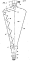
- Figur 6: schematisiert gezeichnete Seitenansicht eines Konus-Schneckenmischers nach der Erfindung.
- Figure 1: Vertical section through the bottom storage of the mixing screw in a cone screw mixer;
- FIG. 2: enlarged partial representation of the seal between the sealing bell and the fixed sealing flange in an embodiment that has been modified. FIG. 1;
- Figure 3: same representation as Figure 1 with explanation of the introduction of rinsing and cooling liquid;
- FIG. 4: an embodiment of the bottom-side mounting with pressure compensation and cooling jacket that has been modified compared to FIG.
- FIG. 5: representation of the rotary drive of the conical joint by means of a geared motor;
- Figure 6: schematically drawn side view of a cone screw mixer according to the invention.
Nach Figur 6 ist in einem konisch in Richtung zum Bodenbereich zulaufenden Mischbehälter 88 eine Mischschnecke 70 angeordnet, welche sich mit der Drehzahl n1 um die Achse 110 dreht und welche sich mit der Drehzahl n2 um die Behälterachse 100 schwenkt. Hierzu ist die Mischschnecke 70 in ihrem oberen Bereich am freien Ende eines Führungsarmes 71 angeordnet, welcher mit der Drehzahl n2 über einen Motor 95 und ein Getriebe 72 angetrieben wird. Am Behälterdeckel sind entsprechende Abdichtungen 73 vorgesehen, um ein Austreten des Produktmediums aus dem Produktraum 80 zu verhindern.According to FIG. 6, a mixing
-Die bodenseitige Lagerung der Mischschnecke 70 erfolgt in der in Figuren 1 bis 5 vorgeschlagenen Weise mit Hilfe eines Kreuzgelenkes 27, wobei die Mischschnecke ihren Drehantrieb (Antrieb um die Achse 110) über eine Gelenkwelle 34 erhält, welche in der Hohlwelle 32 gelagert ist, an deren Ende eine Laterne 62 angeflanscht ist, an deren unterem Ende der Getriebemotor 65 ansetzt.The bottom-side mounting of the mixing
Gemäss Figur 1 ist die Mischschnecke 70 mit einem Kupplungsstück 29 mit Innengewinde fest verschweisst. In dieses Kupplungsstück 29 ist ein Einschraubbolzen 1 so eingeschraubt, daß sich das Gewinde im Betriebsfall von selbst anzieht; d.h. je nach Drehrichtung der Mischschnecke 70 ein Rechts- oder Linksgewinde verwendet wird.According to FIG. 1, the mixing
Anstelle des Kupplungsstückes 29 mit Innengewinde kann eine drehfeste Verbindung von Kupplungsstück 29 und Einschraubbolzen 1 auch mit einer Paßfederverbindung oder einem Abscherstift durchgeführt werden.Instead of the
Auf dem Einschraubbolzen 1 ist eine Buchse 2 aufgezogen.A
Das Wälzlager 6 sowie die Buchse 7 werden spielfrei mittels des Seegerringes 8 auf dem Einschraubbolzen 1 angebracht. Der Einschraubbolzen 1 wird mittels Schrauben 25 drehfest mit dem Oberteil des Kreuzgelenks 27 verbunden. Das Kreuzgelenk-Unterteil wird wiederum mit Schrauben 28 drehfest mit der Gelenkwelle 34 verschraubt.The
Über den Einschraubbolzen 1 mit der Buchse 2, dem Wälzlager 6, der Buchse 7 und dem Seegerring 8 sowie über das Kreuzgelenk 27 wird eine Dichtungsglocke 4 mit eingelassenen Dichtungen 3 geschoben und mittels eines Flansches 10 mit Dichtung 9 sowie Beilagringen 5 axial und radial gesichert. Eine Abdichtung erfolgt über den O-Ring 56. Die Verschraubung erfolgt über die Schrauben 59. Eine Nachschmierung der Lager erfolgt über die Blindschraube 12 der Dichtscheibe 13. Eine zusätzliche Abdichtung ist über den O-Ring 11 gewährleistet. Die Konstruktion und Montage muß gewährleisten, daß der Mittelpunkt des Kreuzgelenkes 27 sowie der Mittelpunkt der Dichtungsglocke 4 ein und derselbe Punkt sind. Hierbei kann die Mischschneckenwelle bis zum 25° schräg zur vertikalen Achse stehen.A sealing
Auf der Gelenkwelle 34 wird eine Buchse 31 (Wellenschonhülse) drehfest aufgezogen. Weiterhin werden die Lager-Innenringe der Lager 36 sowie das Rohr 33 auf die Gelenkwelle 34 aufgezogen und mit dem Seegerring 38 gesichert. Die Gelenkwelle 34 ist mit verschiedenen Zentrierungen für die Lager sowie einem Gewindezapfen 46 mit einem Vierkant versehen.A bushing 31 (shaft sleeve) is rotatably mounted on the cardan shaft 34. Furthermore, the Bearing inner rings of the
Das Lagergehäuse besteht aus einem Rohrgehäuse 18, einem Gegenflansch 52, sowie einer Hohlwelle 32, welche miteinander verschweisst sind.The bearing housing consists of a
Im Rohrgehäuse 18 sind mehrere Montage- und Kontroll- öffnungen angeordnet, welche mit mehreren, am Umfang des Lagergehäuses angeordneten Deckeln 21, den Schrauben 60 und den Dichtringen 19 verschlossen werden.A plurality of assembly and control openings are arranged in the
In der Hohlwelle 32 sind die Außenringe des Lagers 36 eingeschoben und werden mit den Seegerringen 37 gegen axiales Verschieben gesichert. Der Lagerflansch 43 sowie das zweiseitig wirkende Axiallager 40 werden in die Hohlwelle 32 eingeschoben.The outer rings of the
Der Lagerflansch 43 mit dem O-Ring 42 wird nun in die Bohrung der Hohlwelle 32 bzw. über den Aussenring des Lagers 40 geschoben und mit den Schrauben 60 fest mit der Hohlwelle 32 verbunden.The bearing
Der Lagerflansch 39 muß fest am Seegerring 37 anstehen und das Axiallager 40 muß axial nahezu spielfrei eingestellt sein. Weiterhin werden in die Hohlwelle 32 der Wellendichtring 30 sowie der Schmiernippel 58 eingepresst.The bearing
Es wird dann sonach die Gelenkwelle 34 eingeschoben. Durch die Spannscheibe 41, den Federring 47 und die Gewindemutter 48 wird die Gelenkwelle 34 fest mit dem Axiallager 40 verbunden.The propeller shaft 34 is then inserted. The drive shaft 34 is firmly connected to the
Die Verbindung der Mischschnecke 70 mit dem Einschraubbolzen 1 wird durch Drehen des Vierkantes der Gelenkwelle 34 vorgenommen, wobei das Kupplungsstück 29 sich auf das Gewinde des Einschraubbolzens 1 aufschraubt. Dies kann ohne Demontage der Lageranordnung gemacht werden. Nach Durchführung dieser Arbeiten wird der Lagerflansch 43 mit dem Deckel 45, dem O-Ring 44 und den Schrauben 61 verschlossen.The connection of the mixing
Das Lagergehäuse wird mittels Gewindebolzen 55, Muttern 54 und Federringen 53 mit dem Behälterflansch 17 drehfest verschraubt und mit einem O-Ring 26 abgedichtet.The bearing housing is screwed to the
Die Abdichtung zwischen der Dichtungsglocke 4 und dem Behälterflansch 17 wird mit einem Dichtflansch 14, einem Stellflansch 17 mit 0-Ring 16 durchgeführt.The sealing between the sealing
Der Werkstoff des Dichtflansches 14 kann aus Teflon (eingetragenes Warenzeichen für DuPont) oder einem anderen Gleichtlager-Werkstoff sein. Der Werkstoff der Dichtungsglocke 4 muß aus einem gehärteten, plattierten oder Edelstahlmaterial oder einem anderen, zum Dichtflansch 14 passenden,Werkstoff sein.The material of the sealing
Der Dichtflansch 14 hat einen inneren Spülring 49, welcher mit einer Einlass- bzw. Ablassbohrung, welche durch den Stellring 15 durchgebohrt ist, versehen ist. In Fig. 3 ist gezeigt, daß der Ein- bzw. Auslass 75,76 am Lagergehäuse oberhalb der Deckel 21 ansetzt.The sealing
Die Einlass- und Ablassbohrung des Stell- und Dichtflansches 14,15 ist an derselben Stelle,wie die Einlass- bzw. Ablaßbohrung im Behälterflansch 17.The inlet and outlet bores of the adjusting and sealing
Der Stellflansch 15 ist mit einem Schraubbolzen 20 mit Gegenmutter gegen Verdrehung gesichert. Im Stellflansch 15 sind mehrere, federbelastete Vorspannschrauben 24mit Kontermutter 23 und den Federn 22 angebracht. Diese Vorspannschrauben 24 drücken den Stellflansch 15 mit dem Dichtflansch 14 nach unten, gegen die Dichtungsfläche der Dichtungsglocke 4. Die Reibkräfte zwischen Dichtungsglocke 4 und dem Dichtflansch 14 müssen größer sein, als die durch die Wälzlager 6 und durch die Dichtungen 3 und 9 verursachten Reibkräfte. Damit wird gewährleistet, daß die Mischschnecke 70 sich in der Dichtungsglocke 4 dreht und somit die Dichtungsglocke 4 lediglich Kippbewegung entsprechend der Drehzahl n2 durchführt.The adjusting
In Figur 5 ist eine Sonderausführung der erfindungsgemässen Lagerung gezeigt. Die Gelenkwelle 34 ist hierbei mit einem längeren Wellenstumpf versehen, in welchen die Passfeder 66 eingelassen ist. Die axiale Sicherung der Gelenkwelle 34 mit dem Lager 40 erfolgt durch eine Gewindemutter 67. An den Anschlußflansch 43 wird einerseits eine Laterne 62 angeschraubt, auf der anderen Seite wird ein Getriebemotor 65 montiert. Die Drehmoment-Mitnahme vom Getriebemotor 65 zur Gelenkwelle 34 wird über die Passfeder 64 und der Kupplung 63 durchgeführt. Somit kann die Mischschnecke 70 von unten über die Gelenkwelle 34, das Kreuzgelenk 27 und den Einschraubbolzen 1 angetrieben werden.FIG. 5 shows a special version of the bearing according to the invention. The propeller shaft 34 is provided with a longer stub shaft in which the key 66 is embedded. The propeller shaft 34 is axially secured to the
Eine Sonderausführung des Mischschneckenantriebs von unten zeigt die Fig. 7, wobei auf die Gelenkwelle 34 ein Kettenrad 120 drehfest aufgezogen wird. An der Hohlwelle 32 ist ein Motoraufnahmeflansch 121 angebracht. Der Hohlwellengetriebemotor 122 ist mit einem Zwischenflansch 123 mit Schrauben 124 mit dem Motoraufnahmeflansch 121 verbunden. Im Hohlwellengetriebemotor 122 ist eine Antriebswelle 125 mit aufgezogenem Kettenrad drehfest angebracht. Die Kraftübertragung vom Kettenrad 126 auf die Gelenkwelle 34 wird mit einer Kette 127 durchgeführt.FIG. 7 shows a special version of the mixing worm drive from below, a
Die Voraussetzung für den Antrieb von unten wird in Figur 6 noch einmal schematisch erläutert. Wesentlich ist, daß die Mischschnecke 70 von unten angetrieben und oben im Führungsarm 71 geführt wird. Dieser Führungsarm 71 ist drehfest mit einem Getriebemotor 72 verbunden. Die Abdichtung 73 kann durch eine Stopfbüchse, eine Gleitringdichtung oder einem anderen Dichtelement durchgeführt werden. Somit wird die Drehbewegung der Mischschnecke 70 durch den unteren Getriebemotor 65 und die Schwenkbewegung der Mischschnecke durch den oberen Getriebemotor 95,72 gewirkt.The requirement for the drive from below is again schematically explained in FIG. 6. It is essential that the mixing
In Figur 2 ist wesentlich, daß eine Sonderausführung des Dichtflansches 84 dadurch geschaffen wird, daß mehrere Rillen 85,86,87 parallel im Abstand zueinander am Innenumfang des Dichtflansches 84 vorgesehen sind. Hiermit wird ein evtl. eindringendes Produktmedium an den Dichtstellen abgestreift und eine erhöhte Abdichtung erzielt.It is essential in FIG. 2 that a special design of the sealing
Der in Fig. 1 und 3 gezeigte Spülring 49 ermöglicht eine Reinigung der Dichtungsglocke 4 bzw. des Dichtflansches 14 ohne Demontage der Lagerung..Weiterhin kann dieser Spülring 49 als Kühlung für die Dichtungsglocke 4 verwendet werden.The
Gemäss Figur 3 kann der Luftraum 74 zwischen dem Dichtflansch 14 und der Dichtungsglocke 4 und dem Lagergehäuse 18,52,32 als Isolierschicht aufgefasst werden. Außerdem kann das Kreuzgelenk 27 und die abdichtenden Kugelteile von innen mit Sperrflüssigkeit bzw. Kühlflüssigkeit oder einem Gas gespült werden. Hierbei werden jeweils ein Anschluß für Ein- und Ablauf 75,76 der Kühlflüssigkeit im Deckel 21 gemacht.According to FIG. 3, the
Gemäss Figur 4 werden besondere Druckentlastungen vorgesehen. Im Produktraum 80 und im Lagerraum 81 treten ggf. verschiedene Drücke auf. Um die Dichtungen 3,9 sowie den Dichtflansch 14 von diesen zusätzlichen Druckbelastungen zu entlasten, kann ein Druckausgleich zwischen dem Produktraum 80 und dem Lagerraum 81 durchgeführt werden. Hierbei gibt es verschiedene Möglichkeiten. Zum ersten kann eine Druckentlastung des Dichtflansches 14 dadurch gemacht werden, daßAccording to FIG. 4, special pressure relief is provided. In the
der Produktraum 80 mit dem Spülring 49 durch die Druckentlastungsleitung 82 verbunden wird. Soll nur der Lagerraum 81 druckentlastet werden, und damit auch die Dichtungen 3, so muß gemäss Figur 4 eine Druckentlastung mit der zweiten Druckentlastungsleitung 83 durchgeführt werden. Eine optimale Druckentlastung wird durch eine Kombination dieser beiden Druckentlastungsleitungen 82,83 gemäss Figur 4 erreicht.the
Dies hat zur Folge, daß die produktberührten Dichtungen 3,14 wesentlich höhere Standzeiten haben.The consequence of this is that the seals 3.14 in contact with the product have a significantly longer service life.
Sollte eine derartige Druckentlastung bei höheren Betriebstemperaturen durchgeführt werden, kann der untere Lagerblock (Lagergehäuse) zusätzlich mit einem Kühlmantel versehen werden. Hierbei ist gemäss FigurIf such pressure relief is carried out at higher operating temperatures, the lower bearing block (bearing housing) can also be provided with a cooling jacket. Here is according to figure
4 ein unterer Kühlmantel 89 mit dem Einlass 90 und dem Auslass 91 vorgesehen, während das Lagergehäuse selbst durch einen zweiten Kühlmantel 79 mit dem Einlass 68 und dem Auslass 69 gekühlt wird.4, a
In den Lagerraum 74 wird Luft bzw. Sperr- oder Kühlflüssigkeit über den Einlass 77 und den Auslass 78 eingespeist, wobei diese genannten Leitungen jeweils im Deckel 21 angeordnet sein können.Air or barrier or cooling liquid is fed into the
-
1 Einschraubbolzen 31 Buchse1 screw-in
bolt 31 socket -
2 Buchse 32 Hohlwelle2
socket 32 hollow shaft -
3 Dichtung 33 Rohr3
seal 33 tube - 4 Dichtungsglocke 34 Gelenkwelle4 sealing bell 34 PTO shaft
- 5 Beilagring5 washer
-
6 Wälzlager 36 Lager6
bearings 36 bearings -
7 Buchse 37 Seegerring7
Socket 37 Seegerring -
8 Seegerring 38 Seegerring8
circlip 38 circlip -
9 Dichtung 39 Lagerflansch9
Seal 39 bearing flange -
10 Flansch 40 Axiallager10
flange 40 thrust bearing -
11 O-Ring 41 Spannscheibe11 O-
ring 41 tension washer - 12 Blindschraube 42 O-Ring12 blind screw 42 O-ring
-
13 Dichtscheibe 43 Lagerflansch13 sealing
washer 43 bearing flange - 14 Dichtflansch 44 O-Ring14 sealing flange 44 O-ring
-
15 Stellflansch 45 Deckel15
adjustable flange 45 cover -
16 O-Ring 46 Gewindezapfen16 O-
ring 46 threaded pin -
17 Behälterflansch 47 Federring17
Container flange 47 Spring washer -
18 Rohrgehäuse 48 Gewindemutter18
tube housing 48 threaded nut -
19 Dichtring 49 Spülring19
Seal ring 49 Flush ring - 20 Schraubbolzen20 bolts
- 21 Deckel21 lid
-
22 Feder 52 Gegenflansch22
spring 52 counter flange -
23 Kontermutter 53 Federring23
lock nut 53 spring washer -
24 Vorspannschraube 54 Mutter24
preload screw 54 nut -
25 Schraube 55 Gewindebolzen25
screw 55 threaded bolt - 26 O-Ring 56 O-Ring26 O-ring 56 O-ring
- 27 Kreuzgelenk27 universal joint
-
28 Schraube 58 Schmiernippel28
screw 58 grease nipple -
29 Kupplungsstück 59 Schraube29
Coupling piece 59 screw -
30 Wellendichtring 60 Schraube30
shaft seal 60 screw -
61 Schraube 91 Auslaß61
screw 91 outlet - 62 Laterne62 lantern
- 63 Kupplung63 clutch
- 64 Paßfeder64 key
-
65 Getriebemotor 95 Motor65
gear motor 95 motor - 66 Paßfeder66 key
- 67 Gewindemutter67 threaded nut
- 68 Einlaß68 inlet
- 69 Auslaß69 outlet
-
70 Mischschnecke 100 Achse (vertikal)70 mixing
screw 100 axis (vertical) - 71 Führungsarm71 guide arm
- 72- Getriebe72- gear
- 73 Abdichtung73 sealing
- 74 Luftraum74 airspace
- 75 Einlaß75 inlet
- 76 Auslaß76 outlet
- 77 Einlaß77 inlet
- 78 Auslaß78 outlet
- 79 Kühlmantel79 cooling jacket
-
80 Produktraum 110 Achse (geneigt)80
product space 110 axis (inclined) -
81 Lagerraum 120 Kettenrad81
storage room 120 sprocket -
82 Druckentlastungs- 121 Motoraufnahmeflansch leitung82
Pressure relief pipe 121 Motor mounting flange -
83 Druckentlastungs- 122 Hohlwellengetriebemotor leitung83
pressure relief 122 hollow shaft gear motor cable -
84 Dichtflansch 123 Zwischenflansch84 sealing
flange 123 intermediate flange -
85 Rille 124 Schrauben85
groove 124 screws -
86 Rille 125 Antriebswelle86
groove 125 drive shaft -
87 Rille 126 Kettenrad87
groove 126 sprocket -
88 Mischbehälter 127 Kette88 mixing
container 127 chain - 89 Kühlmantel89 cooling jacket
- 90.Einlaß90th inlet
Claims (13)
Priority Applications (1)
| Application Number | Priority Date | Filing Date | Title |
|---|---|---|---|
| AT83109054T ATE24122T1 (en) | 1982-12-11 | 1983-09-14 | CONE SCREW MIXER. |
Applications Claiming Priority (2)
| Application Number | Priority Date | Filing Date | Title |
|---|---|---|---|
| DE19823245935 DE3245935A1 (en) | 1982-12-11 | 1982-12-11 | CONE SCREW MIXER |
| DE3245935 | 1982-12-11 |
Publications (2)
| Publication Number | Publication Date |
|---|---|
| EP0111067A1 true EP0111067A1 (en) | 1984-06-20 |
| EP0111067B1 EP0111067B1 (en) | 1986-12-10 |
Family
ID=6180451
Family Applications (1)
| Application Number | Title | Priority Date | Filing Date |
|---|---|---|---|
| EP83109054A Expired EP0111067B1 (en) | 1982-12-11 | 1983-09-14 | Conical screw mixer |
Country Status (4)
| Country | Link |
|---|---|
| EP (1) | EP0111067B1 (en) |
| AT (1) | ATE24122T1 (en) |
| CA (1) | CA1238901A (en) |
| DE (2) | DE3245935A1 (en) |
Cited By (7)
| Publication number | Priority date | Publication date | Assignee | Title |
|---|---|---|---|---|
| EP0192179A2 (en) | 1985-02-15 | 1986-08-27 | Bolz, Alfred, sen. | Mixer |
| EP0197182A1 (en) * | 1985-04-11 | 1986-10-15 | Bolz, Alfred, sen. | Cone screw mixer with a spheric sealing body in the floor opening |
| EP0222933A1 (en) * | 1985-11-18 | 1987-05-27 | Isem B.V. | Mixing apparatus having a mixing screw and a conical mixing vessel |
| EP0392149A2 (en) * | 1989-04-10 | 1990-10-17 | Bolz, Alfred, sen. | Device for the central pressure lubrication of a cone screw mixer |
| EP0403951A1 (en) * | 1989-06-23 | 1990-12-27 | Krauss-Maffei Aktiengesellschaft | Mixer |
| US6451614B1 (en) | 1999-06-11 | 2002-09-17 | Thermoquest Italia, S.P.A. | Method and device for the vaporization injection |
| CN101902092A (en) * | 2010-08-18 | 2010-12-01 | 顾旭东 | Three-dimensional mixer |
Citations (8)
| Publication number | Priority date | Publication date | Assignee | Title |
|---|---|---|---|---|
| DE533396C (en) * | 1930-10-16 | 1931-09-12 | Clarence Winfred Spicer | Capsule for cardan joints |
| US2008830A (en) * | 1932-01-16 | 1935-07-23 | Chicago Rawhide Mfg Co | Sealing means |
| US3222887A (en) * | 1962-03-05 | 1965-12-14 | Barletta John | Casing for universal joints |
| DE1956007A1 (en) * | 1969-11-07 | 1971-05-13 | Fries Sohn J S | Ball joint with internal universal joint |
| US3933052A (en) * | 1974-10-21 | 1976-01-20 | Coles Carl R | Pressure compensated hermetically sealed transmission system |
| DE2452005A1 (en) * | 1974-11-02 | 1976-05-06 | Werner Wagner Fa | Mixer esp. for pharmaceuticals, cosmetics, etc. - having external drive mechanism |
| DE2701799A1 (en) * | 1976-01-21 | 1977-07-28 | Jan Willem De Vries | CONICAL MIXER WITH MIXING SCREW SUPPORT LY BELOW THE CONTAINER BOTTOM |
| FR2423352A1 (en) * | 1978-04-21 | 1979-11-16 | Uni Cardan Ag | BEARING ASSEMBLY FOR HOMOCINETIC SEAL DRIVEN WHEEL HUB |
Family Cites Families (1)
| Publication number | Priority date | Publication date | Assignee | Title |
|---|---|---|---|---|
| NL6810202A (en) * | 1968-07-18 | 1970-01-20 |
-
1982
- 1982-12-11 DE DE19823245935 patent/DE3245935A1/en not_active Ceased
-
1983
- 1983-09-14 EP EP83109054A patent/EP0111067B1/en not_active Expired
- 1983-09-14 DE DE8383109054T patent/DE3368205D1/en not_active Expired
- 1983-09-14 AT AT83109054T patent/ATE24122T1/en not_active IP Right Cessation
- 1983-12-12 CA CA000443103A patent/CA1238901A/en not_active Expired
Patent Citations (8)
| Publication number | Priority date | Publication date | Assignee | Title |
|---|---|---|---|---|
| DE533396C (en) * | 1930-10-16 | 1931-09-12 | Clarence Winfred Spicer | Capsule for cardan joints |
| US2008830A (en) * | 1932-01-16 | 1935-07-23 | Chicago Rawhide Mfg Co | Sealing means |
| US3222887A (en) * | 1962-03-05 | 1965-12-14 | Barletta John | Casing for universal joints |
| DE1956007A1 (en) * | 1969-11-07 | 1971-05-13 | Fries Sohn J S | Ball joint with internal universal joint |
| US3933052A (en) * | 1974-10-21 | 1976-01-20 | Coles Carl R | Pressure compensated hermetically sealed transmission system |
| DE2452005A1 (en) * | 1974-11-02 | 1976-05-06 | Werner Wagner Fa | Mixer esp. for pharmaceuticals, cosmetics, etc. - having external drive mechanism |
| DE2701799A1 (en) * | 1976-01-21 | 1977-07-28 | Jan Willem De Vries | CONICAL MIXER WITH MIXING SCREW SUPPORT LY BELOW THE CONTAINER BOTTOM |
| FR2423352A1 (en) * | 1978-04-21 | 1979-11-16 | Uni Cardan Ag | BEARING ASSEMBLY FOR HOMOCINETIC SEAL DRIVEN WHEEL HUB |
Cited By (10)
| Publication number | Priority date | Publication date | Assignee | Title |
|---|---|---|---|---|
| EP0192179A2 (en) | 1985-02-15 | 1986-08-27 | Bolz, Alfred, sen. | Mixer |
| EP0192179A3 (en) * | 1985-02-15 | 1989-01-11 | Alfred Sen. Bolz | Mixer |
| EP0197182A1 (en) * | 1985-04-11 | 1986-10-15 | Bolz, Alfred, sen. | Cone screw mixer with a spheric sealing body in the floor opening |
| EP0222933A1 (en) * | 1985-11-18 | 1987-05-27 | Isem B.V. | Mixing apparatus having a mixing screw and a conical mixing vessel |
| EP0392149A2 (en) * | 1989-04-10 | 1990-10-17 | Bolz, Alfred, sen. | Device for the central pressure lubrication of a cone screw mixer |
| EP0392149A3 (en) * | 1989-04-10 | 1992-09-02 | Bolz, Alfred, sen. | Device for the central pressure lubrication of a cone screw mixer |
| EP0403951A1 (en) * | 1989-06-23 | 1990-12-27 | Krauss-Maffei Aktiengesellschaft | Mixer |
| US6451614B1 (en) | 1999-06-11 | 2002-09-17 | Thermoquest Italia, S.P.A. | Method and device for the vaporization injection |
| CN101902092A (en) * | 2010-08-18 | 2010-12-01 | 顾旭东 | Three-dimensional mixer |
| CN101902092B (en) * | 2010-08-18 | 2012-06-06 | 顾旭东 | Three-dimensional mixer |
Also Published As
| Publication number | Publication date |
|---|---|
| DE3245935A1 (en) | 1984-06-14 |
| CA1238901A (en) | 1988-07-05 |
| EP0111067B1 (en) | 1986-12-10 |
| DE3368205D1 (en) | 1987-01-22 |
| ATE24122T1 (en) | 1986-12-15 |
Similar Documents
| Publication | Publication Date | Title |
|---|---|---|
| EP3855021B1 (en) | Eccentric screw pump with mounting through the drive shaft | |
| EP0140097B1 (en) | Pitch changing propeller blade and propulsion for water vehicles | |
| EP0204127B1 (en) | Pressure-resisting mixer | |
| DE602005005487T2 (en) | disperser | |
| EP1423606B1 (en) | Lubrication of a pitch angle adjusting device of a rotor blade of a windmill | |
| DE2348366C3 (en) | Device for pulling off a bulk material, such as chips or the like. from the bottom of a silo | |
| EP0111067A1 (en) | Conical screw mixer | |
| CH637033A5 (en) | CONE SCREW MIXER. | |
| EP1666671B1 (en) | Milling device for trench walls | |
| EP0197182B1 (en) | Cone screw mixer with a spheric sealing body in the floor opening | |
| EP0617999A1 (en) | Mixer with magnetic coupling | |
| EP0054003A2 (en) | Apparatus for agitating, especially mixing and/or drying a stock by means of a receptacle and a screw | |
| EP1626854A1 (en) | Installation for reprocessing materials | |
| EP0403951B1 (en) | Mixer | |
| DE3508711C2 (en) | ||
| DE2701799C2 (en) | mixer | |
| DE2805086A1 (en) | DEVICE FOR COMPENSATING FAILURES OF ORIENTATION BETWEEN A DRIVING AND DRIVING SHAFT | |
| DE3219686A1 (en) | STORAGE UNIT FOR THE CONVEYOR OF A CENTRIFUGE | |
| DE8234869U1 (en) | Cone screw mixer | |
| EP0517178B1 (en) | Conical driver or mixer with swivel arm drive and sealing device | |
| EP0192179B1 (en) | Mixer | |
| DE10317342A1 (en) | High-speed clamping system with manual control used in workpiece processing, has latching piston actuated using balls inside casing and arranged below workpiece pallet, in which shift propulsion latching piston can be done manually | |
| DE2448917A1 (en) | DEVICE FOR REMOVING SCHUETTGUETERN SUCH AS SPAENEN O.DGL. FROM THE BOTTOM OF A SILO | |
| DE3610197C2 (en) | ||
| DE3235533A1 (en) | Shearer drum with nozzles for spraying liquid attached to its peripheral surface |
Legal Events
| Date | Code | Title | Description |
|---|---|---|---|
| PUAI | Public reference made under article 153(3) epc to a published international application that has entered the european phase |
Free format text: ORIGINAL CODE: 0009012 |
|
| AK | Designated contracting states |
Designated state(s): AT BE CH DE FR GB IT LI LU NL SE |
|
| 17P | Request for examination filed |
Effective date: 19841120 |
|
| GRAA | (expected) grant |
Free format text: ORIGINAL CODE: 0009210 |
|
| AK | Designated contracting states |
Kind code of ref document: B1 Designated state(s): AT BE CH DE FR GB IT LI LU NL SE |
|
| REF | Corresponds to: |
Ref document number: 24122 Country of ref document: AT Date of ref document: 19861215 Kind code of ref document: T |
|
| REF | Corresponds to: |
Ref document number: 3368205 Country of ref document: DE Date of ref document: 19870122 |
|
| ITF | It: translation for a ep patent filed |
Owner name: ING.A.GIAMBROCONO & C. S.R.L. |
|
| ET | Fr: translation filed | ||
| PLBE | No opposition filed within time limit |
Free format text: ORIGINAL CODE: 0009261 |
|
| STAA | Information on the status of an ep patent application or granted ep patent |
Free format text: STATUS: NO OPPOSITION FILED WITHIN TIME LIMIT |
|
| 26N | No opposition filed | ||
| ITTA | It: last paid annual fee | ||
| PGFP | Annual fee paid to national office [announced via postgrant information from national office to epo] |
Ref country code: LU Payment date: 19920924 Year of fee payment: 10 |
|
| EPTA | Lu: last paid annual fee | ||
| PG25 | Lapsed in a contracting state [announced via postgrant information from national office to epo] |
Ref country code: LU Free format text: LAPSE BECAUSE OF NON-PAYMENT OF DUE FEES Effective date: 19930914 |
|
| PGFP | Annual fee paid to national office [announced via postgrant information from national office to epo] |
Ref country code: BE Payment date: 19940915 Year of fee payment: 12 |
|
| PGFP | Annual fee paid to national office [announced via postgrant information from national office to epo] |
Ref country code: FR Payment date: 19940923 Year of fee payment: 12 |
|
| PGFP | Annual fee paid to national office [announced via postgrant information from national office to epo] |
Ref country code: SE Payment date: 19940930 Year of fee payment: 12 |
|
| PGFP | Annual fee paid to national office [announced via postgrant information from national office to epo] |
Ref country code: CH Payment date: 19941122 Year of fee payment: 12 |
|
| EAL | Se: european patent in force in sweden |
Ref document number: 83109054.3 |
|
| PG25 | Lapsed in a contracting state [announced via postgrant information from national office to epo] |
Ref country code: SE Effective date: 19950915 |
|
| PG25 | Lapsed in a contracting state [announced via postgrant information from national office to epo] |
Ref country code: LI Effective date: 19950930 Ref country code: CH Effective date: 19950930 Ref country code: BE Effective date: 19950930 |
|
| BERE | Be: lapsed |
Owner name: BOLZ ALFRED SEN. Effective date: 19950930 |
|
| REG | Reference to a national code |
Ref country code: CH Ref legal event code: PL |
|
| PG25 | Lapsed in a contracting state [announced via postgrant information from national office to epo] |
Ref country code: FR Effective date: 19960531 |
|
| EUG | Se: european patent has lapsed |
Ref document number: 83109054.3 |
|
| PGFP | Annual fee paid to national office [announced via postgrant information from national office to epo] |
Ref country code: DE Payment date: 19960813 Year of fee payment: 14 |
|
| PGFP | Annual fee paid to national office [announced via postgrant information from national office to epo] |
Ref country code: GB Payment date: 19960819 Year of fee payment: 14 |
|
| REG | Reference to a national code |
Ref country code: FR Ref legal event code: ST |
|
| PGFP | Annual fee paid to national office [announced via postgrant information from national office to epo] |
Ref country code: NL Payment date: 19960930 Year of fee payment: 14 Ref country code: AT Payment date: 19960930 Year of fee payment: 14 |
|
| PG25 | Lapsed in a contracting state [announced via postgrant information from national office to epo] |
Ref country code: GB Free format text: LAPSE BECAUSE OF NON-PAYMENT OF DUE FEES Effective date: 19970914 Ref country code: AT Free format text: LAPSE BECAUSE OF NON-PAYMENT OF DUE FEES Effective date: 19970914 |
|
| PG25 | Lapsed in a contracting state [announced via postgrant information from national office to epo] |
Ref country code: NL Free format text: LAPSE BECAUSE OF NON-PAYMENT OF DUE FEES Effective date: 19980401 |
|
| GBPC | Gb: european patent ceased through non-payment of renewal fee |
Effective date: 19970914 |
|
| NLV4 | Nl: lapsed or anulled due to non-payment of the annual fee |
Effective date: 19980401 |
|
| PG25 | Lapsed in a contracting state [announced via postgrant information from national office to epo] |
Ref country code: DE Free format text: LAPSE BECAUSE OF NON-PAYMENT OF DUE FEES Effective date: 19980603 |