EP0110819A2 - Device to separate persons when entering an area - Google Patents
Device to separate persons when entering an area Download PDFInfo
- Publication number
- EP0110819A2 EP0110819A2 EP83810439A EP83810439A EP0110819A2 EP 0110819 A2 EP0110819 A2 EP 0110819A2 EP 83810439 A EP83810439 A EP 83810439A EP 83810439 A EP83810439 A EP 83810439A EP 0110819 A2 EP0110819 A2 EP 0110819A2
- Authority
- EP
- European Patent Office
- Prior art keywords
- cabin
- shield
- door
- door leaf
- parts
- Prior art date
- Legal status (The legal status is an assumption and is not a legal conclusion. Google has not performed a legal analysis and makes no representation as to the accuracy of the status listed.)
- Granted
Links
- 238000005192 partition Methods 0.000 claims abstract description 6
- 238000006073 displacement reaction Methods 0.000 claims 1
- 230000004888 barrier function Effects 0.000 abstract 4
- 230000000694 effects Effects 0.000 description 3
- 238000000926 separation method Methods 0.000 description 3
- 238000010586 diagram Methods 0.000 description 2
- 238000005516 engineering process Methods 0.000 description 2
- 239000000463 material Substances 0.000 description 2
- 206010020400 Hostility Diseases 0.000 description 1
- 238000013475 authorization Methods 0.000 description 1
- 230000009194 climbing Effects 0.000 description 1
- 230000001419 dependent effect Effects 0.000 description 1
- 238000002955 isolation Methods 0.000 description 1
- 238000004519 manufacturing process Methods 0.000 description 1
- 238000000034 method Methods 0.000 description 1
- 238000012544 monitoring process Methods 0.000 description 1
- 238000010248 power generation Methods 0.000 description 1
- 230000000284 resting effect Effects 0.000 description 1
- 239000007787 solid Substances 0.000 description 1
- 230000000087 stabilizing effect Effects 0.000 description 1
Images


Classifications
-
- E—FIXED CONSTRUCTIONS
- E05—LOCKS; KEYS; WINDOW OR DOOR FITTINGS; SAFES
- E05G—SAFES OR STRONG-ROOMS FOR VALUABLES; BANK PROTECTION DEVICES; SAFETY TRANSACTION PARTITIONS
- E05G5/00—Bank protection devices
- E05G5/003—Entrance control
-
- G—PHYSICS
- G07—CHECKING-DEVICES
- G07C—TIME OR ATTENDANCE REGISTERS; REGISTERING OR INDICATING THE WORKING OF MACHINES; GENERATING RANDOM NUMBERS; VOTING OR LOTTERY APPARATUS; ARRANGEMENTS, SYSTEMS OR APPARATUS FOR CHECKING NOT PROVIDED FOR ELSEWHERE
- G07C9/00—Individual registration on entry or exit
- G07C9/10—Movable barriers with registering means
- G07C9/15—Movable barriers with registering means with arrangements to prevent the passage of more than one individual at a time
Definitions
- the present invention relates to a device for separating people when entering an area located behind a partition through a passage in the partition.
- a shield 30 is articulated by means of a hinge 12.
- a cabin 20 Connected to the opposite reveal 2 is a cabin 20, which is closed on three sides 21, 22 and 23 and is open on the fourth side 24 against the former reveal 1.
- the shield 30, as shown clearly in FIGS. 2 and 3, is rotatably supported approximately in the middle by means of a hinge 12 and has a dimension such that the open side 24 of the cabin 20 can be at least approximately completely closed.
- the interior of the cabin can be reduced by a chicane 25 in such a way that only one normal adult person has space between the sign 30 closing the open side 24 and the chicane.
- a window 26 can be provided in a side wall, through which a guard can check the person requesting access from a safe position.
- the cabin roof 27 is extended beyond the cabin. This can prevent an intruder from climbing over the shield and gaining unauthorized access when the door is partially open with the shield hinged.
- a room detector 43 and a cabin light 60 can be provided in the cabin itself, on the one hand to indicate that a person is present in the cabin 20 and to create an acceptable illuminated environment for this person. Furthermore, an electrical switch 41, an electrical door opener 38, a key switch 51, an alarm bell 44 can also be provided.
- FIGS. 4 to 6. 4 the door 10 is shown resting on both sides in the frames of the soffits 1 and 2.
- the shield 30 engages with a portion 31 in a guide rail 28 in the baffle 25 of the cabin. A person can thus enter the cabin 20 from the interior I. With the handle 17 on the shield 30, this person can now bring the shield into the position shown in FIG. 5. This completely encloses the person.
- the shield portion 32 which is directed towards the cabin wall 33 with its end face, can latch there.
- Such pawls are well known from the fitting technology and can be designed to be electrically releasable or releasable from the outside by hand.
- the person in the cabin 20 can no longer bring the door and the sign back into the position shown in FIG. 4.
- it can press the label on page 31 so that the position according to FIG. 6 is obtained.
- the person From the position shown in FIG. 4, the person must press the door 10 and the sign 30 into the position shown in FIG. 6 by actuating the handle 13. As a result, the sign snaps behind the lock on the wall 23 and access to the cabin 20 is only free from the outside.
- the entering person now pulls the sign into the position according to FIG. 5.
- the side 32 of the sign cannot solve the entering person alone, but needs either the help from the inside or a special key or a coded access card.
- the shield is formed in two parts and the two parts are arranged so as to be foldable with a vertical hinge arrangement 33.
- the hinge can be released by means of a safety rod (not shown), which can only be actuated from the inside, and the part 31 can be folded onto the part 32 and both parts can then together around the hinge 12 can be folded down on the inside of the door so that the door can be opened into a position as shown in FIG. 7, so that free passage is guaranteed in both directions.
- FIGS. 8 to 11 A second variant of a door is shown in FIGS. 8 to 11.
- a cabin 60 of a hinge arrangement for doors 61 is arranged.
- the door 63 consists of two individual door leaf parts which are connected to one another in an articulated manner on the end face by means of a joint part 66.
- a plate 69 is articulated at the free end 70 of the two door parts.
- two stops 68 are arranged at a distance from one another in the lintel and one door is equipped with a resilient tilting pin, through which avoided can be that the two door parts 64, 65 are in a straight line.
- the two outer parts 71 and 72 of the shield 69 are provided with gripping elements 73 in the form of curved lugs, and round rods 74 are arranged next to the two side walls of the cabin 60 and are partially encompassed by the gripping elements.
- FIG. 8 If a person in FIG. 8 now enters the cabin 60 according to the drawn-out arrow, he can close the cabin by pulling the shield 69, as shown in FIG. 9.
- the door can be electrically locked either on one side or on both sides by means of the round bars 74 and the gripping elements 73.
- an automatic locking is provided on the inside I according to FIG. 9, so that a cabin once closed can no longer be opened towards the inside.
- the person in the cabin can then only open the door according to FIG. 10 and exit to the outside, as the arrow shown clearly shows.
- a person can also enter the cabin from the outside according to the dashed arrow in FIG. 10, then close the cabin according to FIG. 9 and, if access is permitted, open the door according to FIG. 8 in the direction 8 to leave the cabin 60 again.
- This door has the advantage that, due to the special arrangement of one of the two tabs 73, namely in such a way that it can be brought from a locking position into an open position in order to disengage it from the round rods to solve the shield together with the door from a position that is dashed in Figa. 11 is shown, can be brought into one of the two positions shown with solid lines.
- a hook 34 on the inner wall 24 of the cabin 20 is connected to a lifting magnet 39 on the cabin roof via a linkage.
- the solenoid When the solenoid is actuated, the hook 34 is raised and the door is locked.
- a third party can then release the lock from outside the cabin by actuating the push button 38.
- the lifting magnet 39 is de-energized when the cabin is empty.
- the hook 34 is thus in the rest position and the door can be brought into the position according to FIG. 4.
- the room detector 43 reports this and closes the circuit for the lifting magnet 39.
- the hook 34 is raised and the shield is locked on the side wall 24. So that the person in the cabin can get into the interior, the current through the lifting magnet 39 must be interrupted again.
- switch 41 in the cabin wall which can be implemented as a key switch as a code entry device or as a card reader.
- a remotely located safety switch 42 would also be conceivable, which can be actuated from a command point within a secured room.
- a vacant cabin can be indicated with a green lamp 47 and the occupied cabin with a red lamp 46.
- a relay 45 can be attached in the circuit for the magnet 39, which switches the lamp 47 to the current-carrying phase P with contacts 45 in the dropped state and the lamp 46 in the tightened state
- Lamp 46 may be switched on either to indicate outside that there is a person in the cabin or to indicate at the control desk that a person is in the cabin so that the authorization can be checked via an intercom.
- a sign attached to the front edge of a hinged door prevents other people from being forced into it. This can solve the problem the strict isolation of persons recognized as authorized during the entry and exit process is well resolved and absolute restraint is achieved against unauthorized persons.
- the shield in front of the door edge is not rigid but flexible.
- the sign does not have to be moved beyond the cabin, but can be moved via a guide inside the cabin, and secondly, the cabin does not have to be aligned with the axis of the door in the middle position.
- Another advantage is that after pulling out a rod stabilizing the shield, it can be folded in about the middle and can thus be swiveled out of the area of the cabin in order to easily clear the entire passage for the way.
- the chicane in the cabin can prevent with absolute certainty that more than one person is in the cabin. If several people nevertheless pushed into the cabin, the shield would automatically block and could no longer be turned.
- the door can be pivoted open completely by the shield being able to be pivoted into an ineffective position after a lock has been released. This means that any goods can be transported with a normally open passage.
Landscapes
- Physics & Mathematics (AREA)
- General Physics & Mathematics (AREA)
- Business, Economics & Management (AREA)
- Accounting & Taxation (AREA)
- Finance (AREA)
- Lock And Its Accessories (AREA)
- Power-Operated Mechanisms For Wings (AREA)
- Devices For Checking Fares Or Tickets At Control Points (AREA)
- Specific Sealing Or Ventilating Devices For Doors And Windows (AREA)
Abstract
Description
Die vorliegende Erfindung betrifft eine Vorrichtung zum Vereinzeln von Personen beim Betreten eines hinter einer Trennwand befindlichen Gebietes durch einen Durchgang in der Trennwand.The present invention relates to a device for separating people when entering an area located behind a partition through a passage in the partition.
Mit zunehmender Komplexität heutiger Industrie- und Dienstleistungsbetriebe werden diese empflindlicher gegen Störungen jeglicher Art. Parallel dazu lässt sich eine steigende Feindlichkeit gegenüber der Technik und eine zunehmende Kriminalität beobachten. Es ist deshalb immer mehr erforderlich, Beschäftigte und Betriebe vor kriminellen Akten wie Sabotage, Raub oder Terrorakte zu schützen.With increasing complexity of today's industrial and service companies these become more sensitive to disturbances of any kind. At the same time an increasing hostility towards technology and an increasing crime can be observed. It is therefore increasingly necessary to protect employees and companies from criminal acts such as sabotage, robbery or acts of terrorism.
Eines der wirksamsten Mittel zur Abwendung solcher Angriffe besteht im Fernhalten unberechtigter Personen. Insbesondere im Fernhalten solcher Personen von Räumen, in denen Werte oder Daten verarbeitet oder aufbewahrt werden. Ebenso müssen aber auch Fabrikationsanlagen, Energieerzeugungsanlagen oder dgl. geschützt werden und der Zutritt soll nur solchen Personen gestattet sein, die dort etwas zu verrichten haben.One of the most effective ways to avert such attacks is to keep unauthorized people away. In particular, keep such people away from rooms in which values or data are processed or stored. Manufacturing plants, power generation plants or the like must also be protected and access should only be permitted to those who have something to do there.
In der letzten Zeit wurde eine Reihe von Neuerungen eingeführt, die es erlauben, berechtigte von unberechtigten Personen zu unterscheiden. Hierzu gehören insbesondere maschinell lesbare Personalausweise, individuell einzutastende Codes und hochentwickelte Codierungen.A number of innovations have recently been introduced which make it possible to distinguish between legitimate and unauthorized persons. This includes, in particular, machine-readable ID cards, individually keyed codes and sophisticated codes.
Mit der Auslese von berechtigten Personen allein, ist das Problem aber nicht gelöst. Denn eine herkömmliche Tür lässt eine unbeschränkte Anzahl Personen ein, wenn sie einmal offen ist. Insbesondere dann, wenn eine berechtigte Person von einer unberechtigten Person bedroht wird, können unkontrollierbare Personenverschiebungen stattfinden. Eine wirksame Zutrittskontrolle kann deshalb nur dann geschehen, wenn nur einer einzelnen Person der Zutritt ermöglicht wird. In Banken, aber auch bei EDV-Anlagen werden heute bereits vielerorts Drehtüren bzw. Drehkreuze eingesetzt. Wo eine hohe Durchgangskapazität und keine allzuhohe Vereinzelungsqualität erforderlich ist, können solche Anlagen den Ansprüchen genügen. Sie weisen aber insbesondere die nachfolgend genannten Nachteile auf:
- Hoher Raumbedarf, nur beschränkte Tauglichkeit für Notausgänge, für Materialtransporte ungeeignet und ungenügende Vereinzelungswirkung. Die ungenügende Vereinzelungswirkung liegt darin, weil die eintretende Person mit der drehenden Schleuse im Drehkreuz vorwärtsgehen muss. Solche Drehkreuze gestatten überdies nur mit hohem Material- und Kostenaufwand einen befriedigenden Klimaabschluss.
- High space requirements, only limited suitability for emergency exits, unsuitable for material transport and insufficient separation effect. The insufficient separation effect is because the person entering has to go forward with the rotating lock at the turnstile. Such hubs also only allow a satisfactory climate closure with high material and cost expenditure.
Es ist deshalb eine Aufgabe der Erfindung, eine Vorrichtung zu schaffen, mit der zutrittsberechtigte Personen nur einzeln eintreten können und die vor dem Eintreten gegebenenfalls noch überprüft werden können.It is therefore an object of the invention to provide a device with which authorized persons can only enter individually and which, if necessary, can still be checked before entering.
Erfindungsgemäss wird diese Aufgabe durch die Merkmale im kennzeichnenden Teil des unabhängigen Patentanspruchs 1 erreicht. Besonders vorteilhafte Ausführungsformen der Erfindung sind in den abhängigen Ansprüchen beschrieben. Ausführungsbeispiele der Erfindung werden nachfolgend anhand der Zeichnung erläutert. Es zeigen:
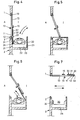
- Fig. 1 einen Aufriss der Türanlage von der Innenseite mit geschnitten dargestellter Kabine,
- Fig. 2 eine Schnittansicht durch die Türe und die Kabine gemäss der Schnittlinie II-II in Fig. 1,
- Fig. 3 eine Schnittansicht durch die Türe und die Kabine gemäss der Schnittlinie III-III in Fig. 1,
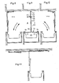
- Fig. 4 bis 6 je einen Grundriss von Türe und Kabine in drei verschiedenen Betriebsstellungen im Normalbetrieb,
- Fig. 7 einen Grundriss einer weiteren Betriebslage bei notausgangsmässig geöffneter Türe,
- Fig. 8 bis 10 je einen Grundriss einer Türe und einer Kabine einer zweiten Ausführungsform in drei Betriebsstellungen,
- Fig. 11 dieselbe Ausführungsform von Türe und Kabine in notfallmässig geöffneter Türe, und
- Fig. 12 ein Schaltungsschema für eine elektrische Überwachung der Türe gemäss Fig. 1 bis 7.
- 1 is an elevation of the door system from the inside with the cabin shown in section,
- 2 is a sectional view through the door and the cabin along the section line II-II in Fig. 1,
- 3 shows a sectional view through the door and the cabin along the section line III-III in FIG. 1,
- 4 to 6 each a floor plan of the door and cabin in three different operating positions in normal operation,
- 7 shows a floor plan of a further operating situation with the door opened in an emergency exit,
- 8 to 10 each a floor plan of a door and a cabin of a second embodiment in three operating positions,
- Fig. 11 the same embodiment of the door and cabin in an emergency open door, and
- 12 shows a circuit diagram for electrical monitoring of the door according to FIGS. 1 to 7.
Die Türe gemäss Fig. 1 bis 3 ist in einen Durchgang D in einer Wand W eingesetzt. Die beiden Laibungen 1 und 2 können in üblicher Ausführungsform mit Zargen Z versehen sein. Ein Türflügel 10 ist an der Zarge rechts in der Zeichnung mittels Bändern 18 drehbar gehaltert. Aussenseitig ist ein Türknauf 16 und innenseitig ein Türdrücker 15 vorgesehen. Am freien Ende 11 des Türflügels ist mittels eines Scharniers 12 ein Schild 30 angelenkt.1 to 3 is inserted into a passage D in a wall W. The two
Anschliessend an die gegenüberliegende Laibung 2 ist eine Kabine 20 angebaut, die auf drei Seiten 21, 22 und 23 geschlossen ist und auf der vierten Seite 24 gegen die erstgenannte Laibung 1 offen ist.Connected to the
Der Schild 30 ist wie Fig. 2 und 3 deutlich zeigen, etwa mittig mittels eines Scharniers 12 drehbar gelagert und hat eine Abmessung, dass die offene Seite 24 der Kabine 20 wenigstens angenähert vollständig verschlossen werden kann. Der Innenraum der Kabine kann durch eine Schikane 25 derart verkleinert sein, dass nur eine einzige normalgebaute erwachsene Person zwischen dem die offene Seite 24 verschliessenden Schild 30 und der Schikane platz hat. In einer Seitenwand kann ein Fenster 26 vorgesehen sein, durch das ein Wächter aus sicherer Stellung heraus die den Zutritt begehrende Person überprüfen kann.The
Wie Fig. 2 deutlich zeigt, ist das Kabinendach 27 über die Kabine hinaus verlängert. Dadurch kann verhindert werden, dass bei teilweise offener Tür mit angelenktem Schild ein Eindringling über den Schild hinwegklettern und sich unerlaubter Weise Zutritt verschaffen kann.As clearly shown in FIG. 2, the
In der Kabine selbst kann ein Raummelder 43 und ein Kabinenlicht 60 vorgesehen sein, um einerseits anzuzeigen, dass eine Person in der Kabine 20 anwesend ist und für diese Person eine annehmbare beleuchtete Umwelt zu schaffen. Ferner können noch ein elektrischer Schalter 41, ein elektrischer Türöffner 38, ein Schlüsselschalter 51, eine Alarmglocke 44 vorgesehen sein.A
Die Funktionsweise einer solchen Vorrichtung zum Vereinzeln von Personen wird nachfolgend anhand der Fig. 4 bis 6 beschrieben. Gemäss Fig. 4 ist die Türe 10 beidseits in den Zargen der Laibungen 1 und 2 anliegend dargestellt. Der Schild 30 greift mit einer Partie 31 in eine Führungsschiene 28 in der Schikane 25 der Kabine ein. Damit kann vom Innenraum I her eine Person in die Kabine 20 eintreten. Mit der Griffmuschel 17 am Schild 30 kann nun diese Person den Schild in die Lage gemäss Fig. 5 bringen. Damit ist die Per-, son vollständig eingeschlossen. Die Schildpartie 32, die mit ihrer Stirnseite gegen die Kabinenwand 33 gerichtet ist, kann dort einklinken. Solche Klinken sind aus der Beschlägetechnik gut bekannt und können elektrisch auslösbar oder von aussen von Hand lösbar ausgebildet sein. Somit kann die Person in der Kabine 20 die Türe und den Schild nicht mehr allein in die Lage gemäss Fig. 4 zurückbringen. Hingegen kann sie den Schild auf der Seite 31 aufdrücken, so dass die Stellung gemäss Fig. 6 erhalten wird. Damit ist der Weg in die Aussenwelt für die Person aus der Kabine 20 frei. Dieser Weg ist in Fig. 4 und 6 durch ausgezogene Pfeile dargestellt. Der umgekehrte Fall, dass eine Person von der Aussenwelt A in einen Innenraum I gelangen will, ist dagegen mit strichliert gezeichneten Pfeilen dargestellt.The operation of such a device for separating people is described below with reference to FIGS. 4 to 6. 4, the
Von der Lage gemäss Fig. 4 muss also die Person durch Betätigung des Drückers 13 die Türe 10 und den Schild 30 in die Lage gemäss Fig. 6 drücken. Dadurch schnappt der Schild hinter die Verriegelung an der Wand 23 ein und der Zugang zur Kabine 20 ist nur von aussen her frei. Die eintretende Person zieht nun den Schild in die Lage gemäss Fig. 5. Die Seite 32 des Schildes kann die eintretende Person jedoch nicht allein lösen, sondern braucht dazu entweder die Hilfe von innen oder einen speziellen Schlüssel oder eine codierte Zutrittskarte.From the position shown in FIG. 4, the person must press the
Selbstverständlich kann die Person jederzeit den Schild auf der Seite 31 aufdrücken, um wieder die Lage gemäss Fig. 6 zu erreichen und aus der Kabine 20 heraus ins Freie zu gelangen.Of course, the person can at any time press the sign on
Bei Warentransporten oder in Notfällen ist vorgesehen, dass sich diese Türe vollständig öffnen lässt. Dazu ist der Schild zweiteilig ausgebildet und die beiden Teile sind mit einer vertikalen Scharnieranordnung 33 klappbar angeordnet. Mittels einer nicht dargestellten nur von der Innenseite aus zu betätigende Sicherheitsstange kann das Scharnier gelöst werden, und der Teil 31 kann auf den Teil 32 geklappt werden und beide Teile zusammen können dann um das Scharnier 12 auf die Innenseite der Türe umgeklappt werden, so dass sich die Türe bis in eine Lage gemäss Fig. 7 öffnen lässt, so dass freier Durchgang in beiden Richtungen gewährleistet ist.When transporting goods or in emergencies, it is provided that this door can be opened completely. For this purpose, the shield is formed in two parts and the two parts are arranged so as to be foldable with a
Eine zweite Variante einer Türe ist in Fig. 8 bis 11 dargestellt. Bei einem Durchgang ist eine Kabine 60 einer Bänderanordnung für Türen 61 angeordnet. Die Türe 63 besteht aus zwei einzelnen Türflügelteilen, die stirnseitig mittels einer Gelenkpartie 66 gelenkig miteinander verbunden sind. Am freien Ende 70 der beiden Türteile ist ein Schild 69 angelenkt. Um in der Totpunktstellung gemäss Fig. 9, wenn die beiden Türteile 64 und 65 in einer geraden Linie angeordnet sind, zu überwinden, sind im Türsturz zwei Anschläge 68 im Abstand voneinander angeordnet und die eine Türe ist mit einem federnden Kippstift ausgerüstet, durch den vermieden werden kann, dass die beiden Türteile 64, 65 in gerader Linie sind.A second variant of a door is shown in FIGS. 8 to 11. In one passage, a
Die beiden Aussenpartien 71 und 72 des Schildes 69 sind mit als gewölbte Laschen ausgebildeten Greifelementen 73 versehen, und neben den beiden Seitenwänden der Kabine 60 sind Rundstangen 74 angeordnet, die durch die Greifelemente teilweise umgriffen werden.The two
Wenn nun eine Person in Fig. 8 gemäss dem ausgezogenen Pfeil in die Kabine 60 hineintritt, kann er durch Ziehen am Schild 69 die Kabine schliessen, wie Fig. 9 zeigt. Durch die Rundstangen 74 und die Greifelemente 73 kann die Türe entweder einseitig oder beidseitig elektrisch verriegelt werden. Jedenfalls ist eine automatische Verriegelung auf der Innenseite I gemäss Fig. 9 vorgesehen, so dass sich eine einmal geschlossene Kabine nicht mehr nach der Innenseite hin öffnen lässt. Die sich in der Kabine befindliche Person kann dann die Tür nur gemäss Fig. 10 öffnen und nach aussen austreten wie der ausgezogene Pfeil deutlich zeigt.If a person in FIG. 8 now enters the
Umgekehrt kann natürlich auch eine Person von aussen gemäss dem strichliert gezeichneten Pfeil in Fig. 10 in die Kabine eintreten, dann die Kabine gemäss Fig. 9 schliessen und, wenn ihm der Zutritt erlaubt ist, die Tür gemäss Fig. 8 öffnen, um in Richtung des strichliert gezeichneten Pfeiles in Fig. 8 die Kabine 60 wieder zu verlassen.Conversely, of course, a person can also enter the cabin from the outside according to the dashed arrow in FIG. 10, then close the cabin according to FIG. 9 and, if access is permitted, open the door according to FIG. 8 in the direction 8 to leave the
Diese Tür hat den Vorteil, dass durch besondere Anordnung einer der beiden Laschen 73, nämlich derart, dass sie sich aus einer Verriegelungsstellung in eine Oeffnungsstellung bringen lassen, um sie aus dem Eingriff mit den Rundstangen zu lösen, sich der Schild zusammen mit der Türe aus einer Lage, die strichliert in Figa. 11 dargestellt ist, in eine der beiden mit ausgezogenen Strichen dargestellte Lage bringen lässt.This door has the advantage that, due to the special arrangement of one of the two
Nachfolgend wird das Schaltungsschema gemäss Fig. 12 in Zusammenhang mit dem Ausführungsbeispiel gemäss Fig. 1 bis 3 beschrieben. Ein Haken 34 an der Innenwand 24 der Kabine 20 ist über ein Gestänge mit einem Hubmagnet 39 auf dem Kabinendach verbunden. Bei Betätigung des Hubmagneten wird der Haken 34 angehoben und die Tür ist verriegelt. Eine Drittperson kann von ausserhalb der Kabine dann durch Betätigung des Drückers 38 die Verriegelung auslösen.The circuit diagram according to FIG. 12 is described below in connection with the exemplary embodiment according to FIGS. 1 to 3. A
Es ist vorgesehen, dass der Hubmagnet 39 bei leerer Kabine stromlos ist. Damit ist der Haken 34 in Ruhelage und die Tür kann in die Lage gemäss Fig. 4 gebracht werden. Sobald eine Person in die Kabine 20 eintritt, meldet dies der Raummelder 43 und schliesst den Stromkreis für den Hubmagneten 39. Dadurch wird der Haken 34 angehoben und der Schild ist an der Seitenwand 24 verriegelt. Damit die in der Kabine befindliche Person in den Innenraum gelangen kann, muss der Strom durch den Hubmagneten 39 wieder unterbrochen werden.It is provided that the lifting
Dies geschieht mittels des Schalters 41 in der Kabinenwand der als Schlüsselschalter als Codeeingeber oder als Kartenleser ausgeführt werden kann. Auch wäre ein entfernt angeordneter Sicherheitsschalter 42 denkbar, der innerhalb eines gesicherten Raumes von einer Kommandostelle aus betätigt werden kann.This is done by means of the
Eine freie Kabine kann mit einer grünen Lampe 47 und die besetzte Kabine mit einer roten Lampe 46 angezeigt werden. Dazu kann im Stromkreis für den Magneten 39 ein Relais 45 angebracht sein, das mit Kontakten 45 im abgefallenen Zustand die Lampe 47 an die stromführende Phase P anschaltet und im angezogenen Zustand die Lampe 46. Ueberdies kann noch eine Sonnerie 44 oder sonst ein Tongeber parallel zur Lampe 46 geschaltet sein, um entweder ausserhalb anzuzeigen, dass sich eine Person in der Kabine befindet, oder beim Kommandopult anzuzeigen, dass sich eine Person in der Kabine befindet, damit die Zulassungsberechtigung über eine Gegensprechanlage überprüft werden kann.A vacant cabin can be indicated with a
Mit einer derartigen Kabinenschleuse, bei denen sich die eintretenswillige Person in die Nische stellt, verhindert ein an der Vorderkante einer Flügeltür befestigter Schild das Nachrängen weiterer Personen. Dadurch kann das Problem der strickten Vereinzelung der zum Zutritt als berechtigt anerkannten Personen während des Eintritts- und Austrittsvorganges gut gelöst und eine absolute Rückhaltewirkung gegenüber unberechtigten Personen erreicht werden.With a cabin lock of this type, in which the person wishing to enter stands in the niche, a sign attached to the front edge of a hinged door prevents other people from being forced into it. This can solve the problem the strict isolation of persons recognized as authorized during the entry and exit process is well resolved and absolute restraint is achieved against unauthorized persons.
Eine solche Tür weist insbesondere die folgenden Vorteile auf:
- Eine hohe Durchgangskapazität. Die Kabine muss nicht nach der Achse der in Mittelstellung befindlichen Tür ausgerichtet sein, und verengt deshalb den Durchgang nicht. Sie kann in ästhetisch befriedigender Weise hinter der Mauer angebaut sein. Für einen Notausgang kann die volle Türbreite benützt werden. Die Schleusenfunktion kann auf Wunsch innert kürzester Zeit aufgehoben werden und die Türe kann als gewöhnliche Schwenktüre benützt werden, wenn die Schleusenfunktion nur während bestimmten Risikosituationen erwünscht ist. Diese Vorrichtung lässt sich überdies bei jeder bereits bestehenden Türe anbringen. Durch die Gewährleistung eines Klimaabschlusses kann eine solche Türe auch an Gebäudeaussenwänden vorgesehen werden.
- A high throughput capacity. The cabin does not have to be aligned with the axis of the door in the middle position and therefore does not restrict the passage. It can be grown behind the wall in an aesthetically satisfactory manner. The full door width can be used for an emergency exit. If desired, the lock function can be released within a very short time and the door can be used as an ordinary swing door if the lock function is only desired during certain risk situations. This device can also be attached to any existing door. By guaranteeing a climate seal, such a door can also be provided on the outer walls of the building.
Diese Vorteile zusammengenommen werden insbesondere dadurch erreicht, dass der der Türkante vorgelagerte Schild nicht starr, sondern beweglich ist. Dadurch muss erstens der Schild nicht über die Kabine hinausbewegt werden, sondern kann über eine Führung innerhalb der Kabine verschoben werden und zweitens, muss die Kabine nicht nach der Achse der in Mittelstellung befindlichen Tür ausgerichtet sein. Ein weiterer Vorteil besteht darin, dass nach Herausziehen eines den Schild stabilisierenden Gestänges, dieser in etwa der Mitte zusammengelegt werden kann und sich dadurch aus dem Bereich der Kabine herausschwenken lässt, um auf einfache Weise den gesamten Durchgang für den Weg frei zu machen.Taken together, these advantages are achieved in particular by the fact that the shield in front of the door edge is not rigid but flexible. As a result, firstly, the sign does not have to be moved beyond the cabin, but can be moved via a guide inside the cabin, and secondly, the cabin does not have to be aligned with the axis of the door in the middle position. Another advantage is that after pulling out a rod stabilizing the shield, it can be folded in about the middle and can thus be swiveled out of the area of the cabin in order to easily clear the entire passage for the way.
Durch die Schikane in der Kabine kann mit absoluter Sicherheit verhindert werden, dass sich mehr als eine einzelne Person im Kabinenraum befindet. Würden sich trotzdem mehrere Personen in die Kabine hineindrängen, so würde der Schild automatisch blockieren und liesse sich nicht mehr weiter drehen.The chicane in the cabin can prevent with absolute certainty that more than one person is in the cabin. If several people nevertheless pushed into the cabin, the shield would automatically block and could no longer be turned.
Es ist offensichtlich, dass mit der angestrebten Wirkung der Tür, jedes Transportieren grosser Gegenstände und das rasche Durchschreiten in Notsituationen verunmöglicht wird.It is obvious that the intended effect of the door makes it impossible to transport large objects and to step through quickly in emergency situations.
Weil es aus räumlichen Gegebenheiten nicht immer möglich ist, angrenzend an die Türschleusen eine zweite Normaltür für diese Sondersituationen einzubauen, wird erfindungsgemäss vorgesehen, dass die Türe vollständig aufgeschwenkt werden kann, indem der Schild nach Aufheben einer Verriegelung in eine unwirksame Stellung geschwenkt werden kann. Dadurch lässt sich jeder Warentransport mit einem normal offenen Durchgang durchführen.Because it is not always possible due to spatial constraints If a second normal door is to be installed adjacent to the door locks for these special situations, it is provided according to the invention that the door can be pivoted open completely by the shield being able to be pivoted into an ineffective position after a lock has been released. This means that any goods can be transported with a normally open passage.
Claims (8)
Priority Applications (1)
| Application Number | Priority Date | Filing Date | Title |
|---|---|---|---|
| AT83810439T ATE48197T1 (en) | 1982-09-29 | 1983-09-29 | DEVICE FOR SEPARATING PERSONS WHEN ENTERING AN AREA. |
Applications Claiming Priority (2)
| Application Number | Priority Date | Filing Date | Title |
|---|---|---|---|
| CH5714/82 | 1982-09-29 | ||
| CH5714/82A CH647838A5 (en) | 1982-09-29 | 1982-09-29 | DEVICE FOR SEPARATING OF PERSONS IN ORDER TO PREVENT UNAUTHORIZED ACCESS CONTROL IN THE rooms behind. |
Publications (3)
| Publication Number | Publication Date |
|---|---|
| EP0110819A2 true EP0110819A2 (en) | 1984-06-13 |
| EP0110819A3 EP0110819A3 (en) | 1987-04-29 |
| EP0110819B1 EP0110819B1 (en) | 1989-11-23 |
Family
ID=4298150
Family Applications (1)
| Application Number | Title | Priority Date | Filing Date |
|---|---|---|---|
| EP83810439A Expired EP0110819B1 (en) | 1982-09-29 | 1983-09-29 | Device to separate persons when entering an area |
Country Status (4)
| Country | Link |
|---|---|
| EP (1) | EP0110819B1 (en) |
| AT (1) | ATE48197T1 (en) |
| CH (1) | CH647838A5 (en) |
| DE (1) | DE3380885D1 (en) |
Cited By (9)
| Publication number | Priority date | Publication date | Assignee | Title |
|---|---|---|---|---|
| FR2731462A1 (en) * | 1995-03-07 | 1996-09-13 | Tech Et Securite | Swing door with fixed main panel and extending secondary panel |
| WO1997020290A1 (en) * | 1995-11-27 | 1997-06-05 | Alex Huber | Device for isolating people |
| NL1003379C2 (en) * | 1996-06-19 | 1997-12-23 | W Van Den Hoogen B V | Door mounted entry control |
| FR2773249A1 (en) * | 1997-11-24 | 1999-07-02 | Huber Alex | Access control arrangement |
| WO1999055995A1 (en) * | 1998-04-29 | 1999-11-04 | Malcolm William Thomas | An access control system |
| EP1143386A1 (en) * | 2000-04-06 | 2001-10-10 | MS Security AG | Arrangement for passage |
| FR2855549A1 (en) * | 2003-05-28 | 2004-12-03 | Serrurerie Ginon | Building e.g. banking agency, secured access providing device, has door moving between passage prohibition and free passage positions, and securing unit restricting movement of another door till former door reaches prohibition position |
| EP1672162A2 (en) * | 2004-12-16 | 2006-06-21 | Anton Posch | Doors |
| ITUB20155357A1 (en) * | 2015-11-03 | 2017-05-03 | Enzo Anselmi | ACCESS CONTROL DEVICE FOR SINGLE PASSAGE |
Families Citing this family (3)
| Publication number | Priority date | Publication date | Assignee | Title |
|---|---|---|---|---|
| CH676621A5 (en) * | 1988-03-17 | 1991-02-15 | Schneebeli Metallbau Ag | Turnstile with inner and outer gates - has swivelling baffle plate, increasing inner space in end position |
| CH687632A5 (en) * | 1992-09-25 | 1997-01-15 | Schneebeli Metallbau Ag | Security personnel airlock. |
| EP2775081A3 (en) | 2013-03-07 | 2018-03-14 | Eugster Sicherheitstechnik | Device for the controlled pick-up and release of a striker |
Citations (10)
| Publication number | Priority date | Publication date | Assignee | Title |
|---|---|---|---|---|
| GB107046A (en) * | ||||
| GB302957A (en) * | 1927-09-21 | 1928-12-21 | Joseph Devonport Finney Andrew | Coin freed apparatus for closet doors |
| US1845743A (en) * | 1930-12-11 | 1932-02-16 | Verna E Davidson | Door construction |
| US2662253A (en) * | 1951-07-10 | 1953-12-15 | William R Winkler | Door for darkrooms |
| US3169329A (en) * | 1962-05-31 | 1965-02-16 | Universal Controls Inc | Turnstile |
| US3445963A (en) * | 1967-07-21 | 1969-05-27 | Roto Swing Door Co Inc | Panic breakaway balance door |
| US3955322A (en) * | 1973-07-02 | 1976-05-11 | Call Jr Charles W | Entry lock |
| DE2735780A1 (en) * | 1977-08-09 | 1979-02-22 | Bochumer Eisen Heintzmann | Personnel admittance checking lock assembly - has single occupancy chamber with light scanner check and contacts on seat in chamber |
| FR2411952A1 (en) * | 1977-12-13 | 1979-07-13 | Decaux Publicite Abribus J C | Door usable by only one person at any time - has leaf with two shutters at angle to each other and lockable in end positions |
| GB2041053A (en) * | 1979-01-31 | 1980-09-03 | Pretini Gisberto | Protective door systems |
-
1982
- 1982-09-29 CH CH5714/82A patent/CH647838A5/en not_active IP Right Cessation
-
1983
- 1983-09-29 DE DE8383810439T patent/DE3380885D1/en not_active Expired
- 1983-09-29 AT AT83810439T patent/ATE48197T1/en not_active IP Right Cessation
- 1983-09-29 EP EP83810439A patent/EP0110819B1/en not_active Expired
Patent Citations (10)
| Publication number | Priority date | Publication date | Assignee | Title |
|---|---|---|---|---|
| GB107046A (en) * | ||||
| GB302957A (en) * | 1927-09-21 | 1928-12-21 | Joseph Devonport Finney Andrew | Coin freed apparatus for closet doors |
| US1845743A (en) * | 1930-12-11 | 1932-02-16 | Verna E Davidson | Door construction |
| US2662253A (en) * | 1951-07-10 | 1953-12-15 | William R Winkler | Door for darkrooms |
| US3169329A (en) * | 1962-05-31 | 1965-02-16 | Universal Controls Inc | Turnstile |
| US3445963A (en) * | 1967-07-21 | 1969-05-27 | Roto Swing Door Co Inc | Panic breakaway balance door |
| US3955322A (en) * | 1973-07-02 | 1976-05-11 | Call Jr Charles W | Entry lock |
| DE2735780A1 (en) * | 1977-08-09 | 1979-02-22 | Bochumer Eisen Heintzmann | Personnel admittance checking lock assembly - has single occupancy chamber with light scanner check and contacts on seat in chamber |
| FR2411952A1 (en) * | 1977-12-13 | 1979-07-13 | Decaux Publicite Abribus J C | Door usable by only one person at any time - has leaf with two shutters at angle to each other and lockable in end positions |
| GB2041053A (en) * | 1979-01-31 | 1980-09-03 | Pretini Gisberto | Protective door systems |
Cited By (12)
| Publication number | Priority date | Publication date | Assignee | Title |
|---|---|---|---|---|
| FR2731462A1 (en) * | 1995-03-07 | 1996-09-13 | Tech Et Securite | Swing door with fixed main panel and extending secondary panel |
| WO1997020290A1 (en) * | 1995-11-27 | 1997-06-05 | Alex Huber | Device for isolating people |
| NL1003379C2 (en) * | 1996-06-19 | 1997-12-23 | W Van Den Hoogen B V | Door mounted entry control |
| FR2773249A1 (en) * | 1997-11-24 | 1999-07-02 | Huber Alex | Access control arrangement |
| WO1999055995A1 (en) * | 1998-04-29 | 1999-11-04 | Malcolm William Thomas | An access control system |
| AU756199B2 (en) * | 1998-04-29 | 2003-01-09 | Malcolm William Thomas | An access control system |
| EP1143386A1 (en) * | 2000-04-06 | 2001-10-10 | MS Security AG | Arrangement for passage |
| EP1189178A1 (en) * | 2000-04-06 | 2002-03-20 | Karl Schlierenzauer | Arrangement for passage |
| FR2855549A1 (en) * | 2003-05-28 | 2004-12-03 | Serrurerie Ginon | Building e.g. banking agency, secured access providing device, has door moving between passage prohibition and free passage positions, and securing unit restricting movement of another door till former door reaches prohibition position |
| EP1672162A2 (en) * | 2004-12-16 | 2006-06-21 | Anton Posch | Doors |
| EP1672162A3 (en) * | 2004-12-16 | 2007-02-21 | Anton Posch | Doors |
| ITUB20155357A1 (en) * | 2015-11-03 | 2017-05-03 | Enzo Anselmi | ACCESS CONTROL DEVICE FOR SINGLE PASSAGE |
Also Published As
| Publication number | Publication date |
|---|---|
| EP0110819A3 (en) | 1987-04-29 |
| ATE48197T1 (en) | 1989-12-15 |
| EP0110819B1 (en) | 1989-11-23 |
| DE3380885D1 (en) | 1989-12-28 |
| CH647838A5 (en) | 1985-02-15 |
Similar Documents
| Publication | Publication Date | Title |
|---|---|---|
| DE69412139T2 (en) | OPERATING LOCKING MECHANISM USED BY CODE, WHICH INCLUDES A TRAP AND A LOCK FOR HOTEL ROOM DOORS | |
| EP0824624B1 (en) | Security device for the lock on a switchgear-cabinet door, machine housing, etc | |
| EP0110819B1 (en) | Device to separate persons when entering an area | |
| DE2702810A1 (en) | PROTECTIVE DEVICE AGAINST THE ENTRY OF PERSONS WITH BAD INTENTIONS INTO A ROOM | |
| DE2830936C2 (en) | Security cell for processing banking or the like. | |
| EP0425431B1 (en) | Lock | |
| DE3700891C2 (en) | ||
| DE9318001U1 (en) | Lock | |
| DE19527801C2 (en) | Locking system | |
| DE3031726A1 (en) | DOOR LOCK | |
| EP0779945B1 (en) | Alarm-triggering closure device for the closure and/or hinge area of a door or window to be made secure | |
| EP1496186B1 (en) | Sluice for controlling passage of persons | |
| DE69904461T2 (en) | ACCESS CONTROL SYSTEM | |
| WO2001003093A1 (en) | Situation detecting device for recognizing the blocking of doors, gates and the like | |
| EP2387010A1 (en) | Evacuation door securing device | |
| EP0440094A1 (en) | Bulkhead for the sealing of the lower part of a door opening, or the like, against fluids, particularly against extinguishing water | |
| DE19631064A1 (en) | Emergency or safety door monitoring and securing device | |
| EP1405974B1 (en) | Locking mechanism for turn and tilt window or door | |
| EP0661080A1 (en) | Fire stop device for a conveyor passing through a wall | |
| DE68920718T2 (en) | Blocking the bolt of a lock. | |
| EP1321610A2 (en) | Lock for a two wing door in escape routes | |
| DE3730031A1 (en) | Revolving door | |
| DE202009005248U1 (en) | Building with at least one building opening and a building closure | |
| EP0364648A1 (en) | Entry lock for persons | |
| DE19723025C2 (en) | Circuit arrangement for closings of electrical door systems, which may not be opened by pressure or suction in the event of danger |
Legal Events
| Date | Code | Title | Description |
|---|---|---|---|
| PUAI | Public reference made under article 153(3) epc to a published international application that has entered the european phase |
Free format text: ORIGINAL CODE: 0009012 |
|
| AK | Designated contracting states |
Designated state(s): AT BE CH DE FR GB IT LI LU NL SE |
|
| PUAL | Search report despatched |
Free format text: ORIGINAL CODE: 0009013 |
|
| AK | Designated contracting states |
Kind code of ref document: A3 Designated state(s): AT BE CH DE FR GB IT LI LU NL SE |
|
| 17P | Request for examination filed |
Effective date: 19871005 |
|
| RAP1 | Party data changed (applicant data changed or rights of an application transferred) |
Owner name: HUBER, ALEX |
|
| 17Q | First examination report despatched |
Effective date: 19880708 |
|
| GRAA | (expected) grant |
Free format text: ORIGINAL CODE: 0009210 |
|
| AK | Designated contracting states |
Kind code of ref document: B1 Designated state(s): AT BE CH DE FR GB IT LI LU NL SE |
|
| REF | Corresponds to: |
Ref document number: 48197 Country of ref document: AT Date of ref document: 19891215 Kind code of ref document: T |
|
| GBT | Gb: translation of ep patent filed (gb section 77(6)(a)/1977) | ||
| REF | Corresponds to: |
Ref document number: 3380885 Country of ref document: DE Date of ref document: 19891228 |
|
| ITF | It: translation for a ep patent filed | ||
| ET | Fr: translation filed | ||
| REG | Reference to a national code |
Ref country code: CH Ref legal event code: PLI Owner name: KLAEY & CO. SICHERHEITSBESCHLAEGE |
|
| PLBE | No opposition filed within time limit |
Free format text: ORIGINAL CODE: 0009261 |
|
| STAA | Information on the status of an ep patent application or granted ep patent |
Free format text: STATUS: NO OPPOSITION FILED WITHIN TIME LIMIT |
|
| 26N | No opposition filed | ||
| ITTA | It: last paid annual fee | ||
| EPTA | Lu: last paid annual fee | ||
| EAL | Se: european patent in force in sweden |
Ref document number: 83810439.6 |
|
| PGFP | Annual fee paid to national office [announced via postgrant information from national office to epo] |
Ref country code: SE Payment date: 19970814 Year of fee payment: 15 Ref country code: AT Payment date: 19970814 Year of fee payment: 15 |
|
| PGFP | Annual fee paid to national office [announced via postgrant information from national office to epo] |
Ref country code: GB Payment date: 19970815 Year of fee payment: 15 |
|
| PGFP | Annual fee paid to national office [announced via postgrant information from national office to epo] |
Ref country code: BE Payment date: 19970822 Year of fee payment: 15 |
|
| PGFP | Annual fee paid to national office [announced via postgrant information from national office to epo] |
Ref country code: LU Payment date: 19970916 Year of fee payment: 15 |
|
| PGFP | Annual fee paid to national office [announced via postgrant information from national office to epo] |
Ref country code: NL Payment date: 19970930 Year of fee payment: 15 |
|
| PG25 | Lapsed in a contracting state [announced via postgrant information from national office to epo] |
Ref country code: LU Free format text: LAPSE BECAUSE OF NON-PAYMENT OF DUE FEES Effective date: 19980929 Ref country code: GB Free format text: LAPSE BECAUSE OF NON-PAYMENT OF DUE FEES Effective date: 19980929 Ref country code: AT Free format text: LAPSE BECAUSE OF NON-PAYMENT OF DUE FEES Effective date: 19980929 |
|
| PG25 | Lapsed in a contracting state [announced via postgrant information from national office to epo] |
Ref country code: SE Free format text: LAPSE BECAUSE OF NON-PAYMENT OF DUE FEES Effective date: 19980930 Ref country code: BE Free format text: LAPSE BECAUSE OF NON-PAYMENT OF DUE FEES Effective date: 19980930 |
|
| BERE | Be: lapsed |
Owner name: HUBER ALEX Effective date: 19980930 |
|
| PG25 | Lapsed in a contracting state [announced via postgrant information from national office to epo] |
Ref country code: NL Free format text: LAPSE BECAUSE OF NON-PAYMENT OF DUE FEES Effective date: 19990401 |
|
| GBPC | Gb: european patent ceased through non-payment of renewal fee |
Effective date: 19980929 |
|
| EUG | Se: european patent has lapsed |
Ref document number: 83810439.6 |
|
| NLV4 | Nl: lapsed or anulled due to non-payment of the annual fee |
Effective date: 19990401 |
|
| PGFP | Annual fee paid to national office [announced via postgrant information from national office to epo] |
Ref country code: FR Payment date: 20000911 Year of fee payment: 18 |
|
| PGFP | Annual fee paid to national office [announced via postgrant information from national office to epo] |
Ref country code: DE Payment date: 20000925 Year of fee payment: 18 |
|
| PG25 | Lapsed in a contracting state [announced via postgrant information from national office to epo] |
Ref country code: DE Free format text: LAPSE BECAUSE OF NON-PAYMENT OF DUE FEES Effective date: 20020501 |
|
| PG25 | Lapsed in a contracting state [announced via postgrant information from national office to epo] |
Ref country code: FR Free format text: LAPSE BECAUSE OF NON-PAYMENT OF DUE FEES Effective date: 20020531 |
|
| REG | Reference to a national code |
Ref country code: FR Ref legal event code: ST |
|
| PGFP | Annual fee paid to national office [announced via postgrant information from national office to epo] |
Ref country code: CH Payment date: 20020826 Year of fee payment: 20 |
|
| PG25 | Lapsed in a contracting state [announced via postgrant information from national office to epo] |
Ref country code: LI Free format text: LAPSE BECAUSE OF EXPIRATION OF PROTECTION Effective date: 20030928 Ref country code: CH Free format text: LAPSE BECAUSE OF EXPIRATION OF PROTECTION Effective date: 20030928 |
|
| REG | Reference to a national code |
Ref country code: CH Ref legal event code: PL |