EP0110760A1 - Installation de nettoyage et décontamination particulaire de vêtements, notamment de vêtements contaminés par des particules radioactives - Google Patents
Installation de nettoyage et décontamination particulaire de vêtements, notamment de vêtements contaminés par des particules radioactives Download PDFInfo
- Publication number
- EP0110760A1 EP0110760A1 EP83402178A EP83402178A EP0110760A1 EP 0110760 A1 EP0110760 A1 EP 0110760A1 EP 83402178 A EP83402178 A EP 83402178A EP 83402178 A EP83402178 A EP 83402178A EP 0110760 A1 EP0110760 A1 EP 0110760A1
- Authority
- EP
- European Patent Office
- Prior art keywords
- solvent
- boiler
- cleaning
- tank
- installation according
- Prior art date
- Legal status (The legal status is an assumption and is not a legal conclusion. Google has not performed a legal analysis and makes no representation as to the accuracy of the status listed.)
- Ceased
Links
Images

Classifications
-
- G—PHYSICS
- G21—NUCLEAR PHYSICS; NUCLEAR ENGINEERING
- G21F—PROTECTION AGAINST X-RADIATION, GAMMA RADIATION, CORPUSCULAR RADIATION OR PARTICLE BOMBARDMENT; TREATING RADIOACTIVELY CONTAMINATED MATERIAL; DECONTAMINATION ARRANGEMENTS THEREFOR
- G21F9/00—Treating radioactively contaminated material; Decontamination arrangements therefor
- G21F9/001—Decontamination of contaminated objects, apparatus, clothes, food; Preventing contamination thereof
-
- B—PERFORMING OPERATIONS; TRANSPORTING
- B01—PHYSICAL OR CHEMICAL PROCESSES OR APPARATUS IN GENERAL
- B01D—SEPARATION
- B01D3/00—Distillation or related exchange processes in which liquids are contacted with gaseous media, e.g. stripping
-
- D—TEXTILES; PAPER
- D06—TREATMENT OF TEXTILES OR THE LIKE; LAUNDERING; FLEXIBLE MATERIALS NOT OTHERWISE PROVIDED FOR
- D06F—LAUNDERING, DRYING, IRONING, PRESSING OR FOLDING TEXTILE ARTICLES
- D06F43/00—Dry-cleaning apparatus or methods using volatile solvents
- D06F43/08—Associated apparatus for handling and recovering the solvents
-
- Y—GENERAL TAGGING OF NEW TECHNOLOGICAL DEVELOPMENTS; GENERAL TAGGING OF CROSS-SECTIONAL TECHNOLOGIES SPANNING OVER SEVERAL SECTIONS OF THE IPC; TECHNICAL SUBJECTS COVERED BY FORMER USPC CROSS-REFERENCE ART COLLECTIONS [XRACs] AND DIGESTS
- Y10—TECHNICAL SUBJECTS COVERED BY FORMER USPC
- Y10S—TECHNICAL SUBJECTS COVERED BY FORMER USPC CROSS-REFERENCE ART COLLECTIONS [XRACs] AND DIGESTS
- Y10S159/00—Concentrating evaporators
- Y10S159/12—Radioactive
Definitions
- the invention relates to a method for cleaning and decontaminating particulate clothing and is particularly applicable to clothing contaminated with radioactive particles.
- clothing can, after service, be contaminated with radioactive, dangerous particles, and must therefore be decontaminated.
- the solvents which currently give the best results are monofluorotrichloromethane, known under the name R 11, and especially trichlorotrifluoroethane known under the name R 113.
- the method according to the invention of the type dry-cleaning solvent medium and operating under atmospheric pressure r ic, wherein the solvent circulates in a closed circuit and is purified by distillation between the outlet and the inlet of the tank cleaning, the drying air also circulating in a closed circuit and being separated from the solvent between the outlet and the inlet of the tank, is characterized in that it cleans independently, when the need arises, each container of solvent from one or other of the circuits, by emptying said container directly at the distillation station and by filling said container with distilled solvent.
- Contaminated waste obtained during several cleaning and decontamination cycles is collected at a single point before being disposed of. Furthermore, the circulation of the solvent, outside the distillation station, takes place only by gravity.
- the invention provides for subjecting the distilled solvent to filtration, outside of any garment cleaning cycle, before introducing it into the tank for a cleaning operation.
- the installation according to the invention which comprises a cleaning drum tank interposed on the one hand in a solvent regeneration circuit of the type with distillation apparatus, condenser, water separator, solvent tank and, on the other hand part, in a circuit for recovering the solvent entrained by the drying air, of the condenser type, is characterized in that each solvent container is linked independently and directly, with interposition of valves, to the boiler of the distillation apparatus for independent cleaning purposes.
- the solvent recovery circuit advantageously comprises a refrigerated battery ensuring the condensation of the solvent vapors, the solvent recovery being connected upstream of the water separator of the solvent regeneration circuit.
- the installation also includes, in the solvent regeneration circuit, a water recovery tank disposed downstream of the water separator and which is directly connected to the boiler.
- the boiler is removably mounted on the distillation column.
- the boiler comprises a tank for collecting used solvents and contaminated waste independent of the heating means.
- the latter can be constituted by a bain-marie tank.
- the same boiler can be reused after it has undergone proper cleaning. If, on the other hand, the contamination is too great, the invention provides for throwing out the boiler after all the contaminated waste has been collected there.
- the installation can be completed by a filtration device with several cartridges of decreasing porosity interposed between the distilled solvent tank and the cleaning and decontamination tank.
- the cartridges are then advantageously made of borosilicate fibers.
- the elements of the solvent regeneration and recovery circuits are brought together in the same module intended to remain in a contaminated room, the washing tank and its departures and returns from various pipes constituting a second module with two openings of which only the clothing unloading opening is intended to be in communication with the clean room.
- the installation for cleaning and particulate decontamination of clothing according to the invention is particularly intended for nuclear decontamination.
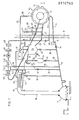
- FIG. 1 It comprises (FIG. 1) a tank 10 with an interior drum 11 into which the clothes are introduced, this tank having two openings, one 12 on the front wall and the other 13 on the side wall, these two openings being distinct one on the other and used only for the introduction of dirty and contaminated clothing, and the other for unloading clean and decontaminated clothing.
- a conduit 14 which opens at the bottom of the tank and into which are interposed a filter 15 with large meshes intended to retain large solids or "button filter”, as well as a valve 16 for emptying the tank , reaches bcuilleur 17 of a distillation apparatus.
- This boiler will be described in more detail below.
- the distillation apparatus further comprises a column 18, the upper end of which is connected to a condenser 19 equipped with a cold battery 20 in the form of a coil in which a refrigerated fluid, for example water, circulates.
- a refrigerated fluid for example water
- the condenser 19 is formed at the bottom as a tank 21 for storing solvent and decanting, having regard to the particles of water that the solvent may contain, and is connected by an overflow pipe 22 to a water separator 23, of the densimetric type, connected by a conduit 24, the end of which opens at the bottom of the separator, to a reservoir 25 of freshly distilled solvent.
- This reservoir 25 is connected by a conduit 26 in which is interposed a valve 27 for admitting solvent to the tank 10 for cleaning and decontaminating clothing.
- each solvent container of the regeneration circuit of the solvent which has just been described is connected independently and directly to the boiler 17: the drum tank, as already indicated, by the conduit 14; the reservoir 25 by a conduit 28 in which is mounted a manual drain valve 29; the water separator 23 by a conduit 30 in which is mounted a manual drain valve 31; and the distillation condenser 19 through a conduit 32 in which is mounted a manual drain valve 33.
- the solvent regeneration circuit also comprises a tank 34 for storing the water separated in the separator 23 to which it is connected by a pipe 35, this water storage tank 34 being itself connected independently, by a pipe 36 in which is mounted a manual drain valve 37, to the pipe 14 which opens directly into the boiler 17.
- the solvent circuit which has just been described also includes adjuvant reservoirs, for example a reservoir 38 of cleaning adjuvant as well as a reservoir 41 of rinsing adjuvant each communicating by a conduit 39, respectively 42, equipped with a metering valve 40, respectively 43, with the conduit 26 bringing the freshly distilled solvent into the tank 10.
- adjuvant reservoirs for example a reservoir 38 of cleaning adjuvant as well as a reservoir 41 of rinsing adjuvant each communicating by a conduit 39, respectively 42, equipped with a metering valve 40, respectively 43, with the conduit 26 bringing the freshly distilled solvent into the tank 10.
- the arrangement of the various devices of the solvent regeneration circuit namely condenser 19, separator 23, water storage tank 34, distilled solvent tank 25, tank 10 with drum and boiler , relative to each other is such that the solvent flows by gravity from the condenser to the tank and from the latter to the boiler, on the one hand, and that, likewise, the various solvent containers are in communication by gravity with the boiler.
- the bottoms of the various solvent containers are advantageously frustoconical or pyramidal to facilitate flow by gravity, the diameters of the various solvent circulation ducts being provided sufficiently large for the same purpose.
- the installation also includes a circuit for recovering the solvent entrained by the drying air.
- This circuit includes a duct 44 for air intake to the drum tank in which is mounted an air inlet valve 45, and a duct 46 for return or return air, in which is mounted a air intake 47 then, successively, a so-called “lint” prefilter 48, a dust and particle filter 49, a fan or blower 50 ensuring the circulation of air, a separator and solvent recuperator 51 with a cold battery formed by a coil 52 in which a refrigerant circulates and finally an air heating coil 53.
- the solvent recuperator 51 is connected by a conduit 54 to the conduit 22 for supplying solvent into the water separator 23. It is also independently connected to the boiler, with the interposition of a manual drain valve 56, by a conduit 55 which opens directly into the duct 14 leading to the boiler 17.
- the installation according to the invention which operates under atmospheric pressure, also comprises a pressure balancing system comprising a pipe 57 connected, on the one hand, to the upper internal volume of the tank 10 with the interposition of a valve 58 for isolating the tank and for pressure balancing and, on the other hand, either to the reservoir 25 via a three-way valve 59 and a pipe 60, or to an expansion tank 61.
- pressure equalization pipes are provided which interconnect the interior volumes of each container capable of being filled with solvent.
- the invention optionally provides to equip the installation with a filtration device in which, if desired for particularly advanced decontamination, circulate the distilled solvent before introducing it into the tank 10.
- a filtration device in which, if desired for particularly advanced decontamination, circulate the distilled solvent before introducing it into the tank 10.
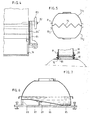
- This filtration device shown in FIG. 2 comprises, connected to the reservoir 25 by a conduit 62 fitted with a valve 63, a solvent reservoir 64, acting as a buffer reservoir, which is connected by a conduit 65 comprising a pump circulation 66 to several filtration cartridges arranged in series 67, 68, 69, of successively decreasing porosity, for example 2 ⁇ , 0.9 ⁇ and 0.3 ⁇ .
- the last cartridge 69 is connected to a reservoir 70 of filtered distilled solvent, which is connected by a conduit 71 to the inlet of solvent into the tank 10.
- pressure equalization pipes for example a pipe 72 comprising a valve 72 'between the tanks 70 and 64 and a pipe 73, in which a valve 73' is mounted, between the tanks 64 and 25.
- the filters of the cartridges 67, 68, 69 are advantageously made of borosilicate microfibers, which makes it possible to vitrify them when they are contaminated with nuclear waste.
- the boiler is independent of the distillation column.
- FIG. 3 it comprises a container 74, or boiler proper, intended to contain the solvent, of substantially semi-cylindrical conformation, and the bottom 75 of which is shaped so as to increase the surface of exchange, for example sawtooth as shown in Figure 3.
- This container 74 is pierced on its upper wall with an orifice 74 'of communication with column 18 of advantageously circular section.
- the section of the orifice and that of the column are of appropriate dimensions to, on the one hand, ensure a distillation flow rate without braking of the solvent vapors and, on the other hand, allow the filters used to be introduced into the boiler. , i.e. filters 15, 48, 49, as well as filter cartridges 67, 68, 69.
- the boiler 74 is carried by a tank 76 of heating fluid, in particular of the bain-marie type, itself supported by a lifting plate 77 subjected for example to the action of jacks, eccentrics or the like.
- the orifice 74 ′ is surrounded by a circular collar 78 projecting towards the outside, on which a neoprene annular seal 79 with a U-shaped section can be inserted, intended to fit inside a circular angle 80 outside surrounding the mouth of the distillation column 18.
- the invention also provides to attach to the side walls of the boiler 74, near the bottom 75, longitudinal angles 81 which can be used for several purposes: they can allow the fixing of threaded rods 82 on which are introduced nuts 83 for fixing in closed position of front or rear doors 84 of the bain-marie tank 76, neoprene plates 84 'being interposed to form a seal between a door and the wall of the boiler (FIG. 4); they can be used as points attachment of the boiler lifting rings; when, in a preferred embodiment of the invention, two symmetrical boilers 74 1 , 74 2 (FIG. 5) can be assembled by cooperation of their bottoms 75, the angles 81 1 , 81 2 can contribute to the connection between the two boilers by any appropriate connection means attached to each of them.
- FIG. 6 shows another embodiment of the boiler which comprises, integrated, the heating means, for example a coil 85 in which any suitable heating fluid circulates.
- the boiler the bottom of which has a median part 86 inclined to allow the housing in the lower part of the coil, is supported by a lifting plate 87 by means of spacers 88, 89.
- Figure 7 shows a variant of the removable fixing system of the boiler on the column.
- the orifice 74 ′ is here bordered by an annular collar 90 of the same cross section as the distillation column 18.
- a neoprene sleeve 91 can be fitted on the collar 90 and the column 18 and connect these two elements to the seal. using clamps 92 and 93.
- This embodiment makes it possible to eliminate the use of a lifting plate for the boiler, the latter being able to be directly lifted by suitable lifting means to be put in position for connection with the column, or took of.
- all the parts of the installation constituting the regeneration and solvent recovery circuits are gathered in the same module, for example housed in the same cabinet intended to remain in a "contaminated" room.
- the tank 10 as well as the arrivals and returns of the various pipes 14, 26, 46, 57 and, optionally, the systems for introducing adjuvants, constitute a second module, for example a cabinet closed with two openings of which only one, to know that allowing the unloading of the drum is in a "clean" room.
- the barrier B in FIG. 1 symbolizes the separation between the two modules, that is to say between the contaminated part and the clean part of the installation.
- Radiation measurement devices can be mounted in the clean module part to allow an appreciation of the quality of decontamination obtained at the end of the cleaning operation. These devices can automatically control, by any suitable means, the locking, for example electromechanical or other, of the tank unloading door in the event of unsatisfactory decontamination of the clean module.
- the installation works as follows, for example for a two-bath cycle.
- the valves 58, 16, 27, 47 and 45 being closed, dirty and contaminated clothing is loaded by the introduction opening 13 of the tank.
- the valve 27 is opened for the time necessary for the flow of the quantity of solvent desired in the tank and the drum, the adjuvant metering valve 40 possibly being open.
- the drum motor After closing the valve 27, and opening the valves 58 and 59 for the communication of the tank with the expansion tank 61, the drum motor is started for the desired washing operation.
- the drain valve 16 is opened so that the spent solvent flows into the boiler, by rapidly rotating the drum at the end of the solvent flow phase.
- a second filling of the drum is then carried out with solvent and optionally a rinsing aid, then, after bubbling at the appropriate speed of rotation of the drum, the spent solvent is allowed to flow as after the washing operation.
- valves 16, 27 and 58 are then closed and the drying phase is started by introducing air.
- the valves 45 and 47 are opened, for air intake and return, the fan 50 sucking in the air and the solvent vapors which escape from the clothing into the solvent recuperator 51 after passing through the filters 48 and 49.
- the air cooled after passing through the recuperator 51 with refrigerated condenser is reheated in the coil 53 then returns to the drum tank. During the entire drying period, the drum is rotated.
- any solvent container for example the water separator 23, it is sufficient, by opening the manual valve 31, to empty the separator into the boiler 17 and to distill the solvent from emptying, which allows the separator to be filled with freshly distilled solvent. The operation is then repeated until no contamination can no longer be detected in the separator. The same is done in the event of contamination of any of the solvent reservoirs, namely condenser 19, reservoir 25, recuperator 51, by emptying the latter by opening the associated manual emptying valve. To properly clean the drum, add an appropriate amount of solvent to it and rotate the drum at high speed, after which the solvent is allowed to flow into the boiler.
- the invention thus provides a simple and safe operating installation in that each of its parts can be maintained and cleaned independently and without difficulty, that all contaminated waste can be collected in one and the same point, namely the boiler, which can then be discarded.
Landscapes
- Engineering & Computer Science (AREA)
- Textile Engineering (AREA)
- Chemical & Material Sciences (AREA)
- Chemical Kinetics & Catalysis (AREA)
- Life Sciences & Earth Sciences (AREA)
- Food Science & Technology (AREA)
- Physics & Mathematics (AREA)
- General Engineering & Computer Science (AREA)
- High Energy & Nuclear Physics (AREA)
- Vaporization, Distillation, Condensation, Sublimation, And Cold Traps (AREA)
- Cleaning By Liquid Or Steam (AREA)
- Accessory Of Washing/Drying Machine, Commercial Washing/Drying Machine, Other Washing/Drying Machine (AREA)
Applications Claiming Priority (2)
| Application Number | Priority Date | Filing Date | Title |
|---|---|---|---|
| FR8219457 | 1982-11-19 | ||
| FR8219457A FR2536433A1 (fr) | 1982-11-19 | 1982-11-19 | Procede et installation de nettoyage et decontamination particulaire de vetements, notamment de vetements contamines par des particules radioactives |
Publications (1)
| Publication Number | Publication Date |
|---|---|
| EP0110760A1 true EP0110760A1 (fr) | 1984-06-13 |
Family
ID=9279359
Family Applications (1)
| Application Number | Title | Priority Date | Filing Date |
|---|---|---|---|
| EP83402178A Ceased EP0110760A1 (fr) | 1982-11-19 | 1983-11-10 | Installation de nettoyage et décontamination particulaire de vêtements, notamment de vêtements contaminés par des particules radioactives |
Country Status (4)
| Country | Link |
|---|---|
| US (1) | US4601181A (https=) |
| EP (1) | EP0110760A1 (https=) |
| JP (1) | JPS59105499A (https=) |
| FR (1) | FR2536433A1 (https=) |
Cited By (1)
| Publication number | Priority date | Publication date | Assignee | Title |
|---|---|---|---|---|
| DE3543244A1 (de) * | 1984-12-10 | 1986-06-19 | Quadrex Hps Inc | Verfahren und apparatur zum reinigen von kleidung und textilien, die mit spaltbaren, chemischen und/oder biologischen substanzen verunreinigt sind |
Families Citing this family (69)
| Publication number | Priority date | Publication date | Assignee | Title |
|---|---|---|---|---|
| US4781041A (en) * | 1984-12-10 | 1988-11-01 | Quadrex Hps, Inc. | Apparatus for cleaning garments and soft goods contaminated with nuclear, chemical and/or biological contaminants |
| US4917807A (en) * | 1986-02-21 | 1990-04-17 | Westinghouse Electric Corp. | Method for recovering solvent |
| US4770197A (en) * | 1986-02-21 | 1988-09-13 | Westinghouse Electric Corp. | Apparatus for recovering solvent |
| US4955403A (en) * | 1988-11-30 | 1990-09-11 | Westinghouse Electric Corp. | Closed loop system and method for cleaning articles with a volatile cleaning solvent |
| US5090221A (en) * | 1988-11-30 | 1992-02-25 | Westinghouse Electric Corp. | Continuous circulation water wash apparatus and method for cleaning radioactively contaminated garments |
| US4879888A (en) * | 1988-12-12 | 1989-11-14 | Moshe Suissa | Dry cleaning machine |
| US5248393A (en) * | 1990-01-31 | 1993-09-28 | S&K Products International, Inc. | Solvent reprocessing system |
| US5538025A (en) * | 1991-11-05 | 1996-07-23 | Serec Partners | Solvent cleaning system |
| US5702535A (en) * | 1991-11-05 | 1997-12-30 | Gebhard-Gray Associates | Dry cleaning and degreasing system |
| US5630434A (en) * | 1991-11-05 | 1997-05-20 | Gray; Donald J. | Filter regeneration system |
| US5308452A (en) * | 1992-01-31 | 1994-05-03 | Progressive Recovery, Inc. | Photopolymer washout fluid solvent distillation apparatus and method |
| US5377705A (en) * | 1993-09-16 | 1995-01-03 | Autoclave Engineers, Inc. | Precision cleaning system |
| JPH0882697A (ja) * | 1994-09-13 | 1996-03-26 | Morikawa Sangyo Kk | 放射性汚染物の除染方法及び除染装置 |
| US6045588A (en) | 1997-04-29 | 2000-04-04 | Whirlpool Corporation | Non-aqueous washing apparatus and method |
| US6306564B1 (en) | 1997-05-27 | 2001-10-23 | Tokyo Electron Limited | Removal of resist or residue from semiconductors using supercritical carbon dioxide |
| US6500605B1 (en) | 1997-05-27 | 2002-12-31 | Tokyo Electron Limited | Removal of photoresist and residue from substrate using supercritical carbon dioxide process |
| TW539918B (en) | 1997-05-27 | 2003-07-01 | Tokyo Electron Ltd | Removal of photoresist and photoresist residue from semiconductors using supercritical carbon dioxide process |
| US5946945A (en) * | 1997-12-24 | 1999-09-07 | Kegler; Andrew | High pressure liquid/gas storage frame for a pressurized liquid cleaning apparatus |
| US6277753B1 (en) | 1998-09-28 | 2001-08-21 | Supercritical Systems Inc. | Removal of CMP residue from semiconductors using supercritical carbon dioxide process |
| US6334340B1 (en) * | 1999-10-08 | 2002-01-01 | Alliance Laundry Systems Llc | Liquified gas dry-cleaning machine with convertible installation configuration |
| US6748960B1 (en) * | 1999-11-02 | 2004-06-15 | Tokyo Electron Limited | Apparatus for supercritical processing of multiple workpieces |
| KR100744888B1 (ko) * | 1999-11-02 | 2007-08-01 | 동경 엘렉트론 주식회사 | 소재를 초임계 처리하기 위한 장치 및 방법 |
| US6890853B2 (en) * | 2000-04-25 | 2005-05-10 | Tokyo Electron Limited | Method of depositing metal film and metal deposition cluster tool including supercritical drying/cleaning module |
| US7513132B2 (en) * | 2003-10-31 | 2009-04-07 | Whirlpool Corporation | Non-aqueous washing machine with modular construction |
| AU2001290171A1 (en) * | 2000-07-26 | 2002-02-05 | Tokyo Electron Limited | High pressure processing chamber for semiconductor substrate |
| EP1573779A4 (en) * | 2001-04-10 | 2006-11-15 | Tokyo Electron Ltd | HIGH PRESSURE PROCESSING CHAMBER FOR A SEMICONDUCTOR SUBSTRATE WITH FLOW IMPROVEMENT FEATURES |
| US20050115005A1 (en) * | 2001-07-17 | 2005-06-02 | Kohei Sawa | Dry cleaning machine and method of dry cleaning |
| US20040040660A1 (en) * | 2001-10-03 | 2004-03-04 | Biberger Maximilian Albert | High pressure processing chamber for multiple semiconductor substrates |
| US7001468B1 (en) | 2002-02-15 | 2006-02-21 | Tokyo Electron Limited | Pressure energized pressure vessel opening and closing device and method of providing therefor |
| JP2005517884A (ja) * | 2002-02-15 | 2005-06-16 | 東京エレクトロン株式会社 | 圧力強化ダイヤフラム弁 |
| US7387868B2 (en) * | 2002-03-04 | 2008-06-17 | Tokyo Electron Limited | Treatment of a dielectric layer using supercritical CO2 |
| US20040112409A1 (en) * | 2002-12-16 | 2004-06-17 | Supercritical Sysems, Inc. | Fluoride in supercritical fluid for photoresist and residue removal |
| US7021635B2 (en) * | 2003-02-06 | 2006-04-04 | Tokyo Electron Limited | Vacuum chuck utilizing sintered material and method of providing thereof |
| US20040154647A1 (en) * | 2003-02-07 | 2004-08-12 | Supercritical Systems, Inc. | Method and apparatus of utilizing a coating for enhanced holding of a semiconductor substrate during high pressure processing |
| US7077917B2 (en) * | 2003-02-10 | 2006-07-18 | Tokyo Electric Limited | High-pressure processing chamber for a semiconductor wafer |
| US7225820B2 (en) * | 2003-02-10 | 2007-06-05 | Tokyo Electron Limited | High-pressure processing chamber for a semiconductor wafer |
| US7270137B2 (en) | 2003-04-28 | 2007-09-18 | Tokyo Electron Limited | Apparatus and method of securing a workpiece during high-pressure processing |
| US7163380B2 (en) * | 2003-07-29 | 2007-01-16 | Tokyo Electron Limited | Control of fluid flow in the processing of an object with a fluid |
| US20050035514A1 (en) * | 2003-08-11 | 2005-02-17 | Supercritical Systems, Inc. | Vacuum chuck apparatus and method for holding a wafer during high pressure processing |
| US20050034660A1 (en) * | 2003-08-11 | 2005-02-17 | Supercritical Systems, Inc. | Alignment means for chamber closure to reduce wear on surfaces |
| US20050067002A1 (en) * | 2003-09-25 | 2005-03-31 | Supercritical Systems, Inc. | Processing chamber including a circulation loop integrally formed in a chamber housing |
| US7739891B2 (en) | 2003-10-31 | 2010-06-22 | Whirlpool Corporation | Fabric laundering apparatus adapted for using a select rinse fluid |
| US7186093B2 (en) * | 2004-10-05 | 2007-03-06 | Tokyo Electron Limited | Method and apparatus for cooling motor bearings of a high pressure pump |
| US20050224099A1 (en) * | 2004-04-13 | 2005-10-13 | Luckman Joel A | Method and apparatus for cleaning objects in an automatic cleaning appliance using an oxidizing agent |
| WO2005106105A1 (en) | 2004-04-29 | 2005-11-10 | Unilever N.V. | Dry cleaning method |
| US7250374B2 (en) | 2004-06-30 | 2007-07-31 | Tokyo Electron Limited | System and method for processing a substrate using supercritical carbon dioxide processing |
| US7307019B2 (en) | 2004-09-29 | 2007-12-11 | Tokyo Electron Limited | Method for supercritical carbon dioxide processing of fluoro-carbon films |
| US20060065189A1 (en) * | 2004-09-30 | 2006-03-30 | Darko Babic | Method and system for homogenization of supercritical fluid in a high pressure processing system |
| US7491036B2 (en) | 2004-11-12 | 2009-02-17 | Tokyo Electron Limited | Method and system for cooling a pump |
| US20060134332A1 (en) * | 2004-12-22 | 2006-06-22 | Darko Babic | Precompressed coating of internal members in a supercritical fluid processing system |
| US7434590B2 (en) | 2004-12-22 | 2008-10-14 | Tokyo Electron Limited | Method and apparatus for clamping a substrate in a high pressure processing system |
| US7140393B2 (en) | 2004-12-22 | 2006-11-28 | Tokyo Electron Limited | Non-contact shuttle valve for flow diversion in high pressure systems |
| US7435447B2 (en) | 2005-02-15 | 2008-10-14 | Tokyo Electron Limited | Method and system for determining flow conditions in a high pressure processing system |
| US7291565B2 (en) | 2005-02-15 | 2007-11-06 | Tokyo Electron Limited | Method and system for treating a substrate with a high pressure fluid using fluorosilicic acid |
| US7767145B2 (en) * | 2005-03-28 | 2010-08-03 | Toyko Electron Limited | High pressure fourier transform infrared cell |
| US7380984B2 (en) * | 2005-03-28 | 2008-06-03 | Tokyo Electron Limited | Process flow thermocouple |
| US20060225772A1 (en) * | 2005-03-29 | 2006-10-12 | Jones William D | Controlled pressure differential in a high-pressure processing chamber |
| US7494107B2 (en) * | 2005-03-30 | 2009-02-24 | Supercritical Systems, Inc. | Gate valve for plus-atmospheric pressure semiconductor process vessels |
| US7789971B2 (en) | 2005-05-13 | 2010-09-07 | Tokyo Electron Limited | Treatment of substrate using functionalizing agent in supercritical carbon dioxide |
| US7966684B2 (en) | 2005-05-23 | 2011-06-28 | Whirlpool Corporation | Methods and apparatus to accelerate the drying of aqueous working fluids |
| US20060260064A1 (en) * | 2005-05-23 | 2006-11-23 | Luckman Joel A | Methods and apparatus for laundering with aqueous and non-aqueous working fluid |
| US7524383B2 (en) | 2005-05-25 | 2009-04-28 | Tokyo Electron Limited | Method and system for passivating a processing chamber |
| US20070044427A1 (en) * | 2005-08-26 | 2007-03-01 | Atomic Energy Council - Institute Of Nuclear Energy Research | Submarine ultrasonic cleaning machine |
| KR200458209Y1 (ko) | 2009-07-23 | 2012-01-30 | 김원희 | 스포팅 머신 |
| US8470136B2 (en) * | 2010-02-02 | 2013-06-25 | Safety-Kleen Systems, Inc. | Parts washer with recycler assembly |
| US8470137B2 (en) * | 2010-02-02 | 2013-06-25 | Safety-Kleen Systems, Inc. | Recycler assembly |
| US8506761B2 (en) * | 2010-02-02 | 2013-08-13 | Safety-Kleen Systems, Inc. | Recycler module for a recycler assembly |
| US8425732B2 (en) * | 2010-02-02 | 2013-04-23 | Safety-Kleen Systems, Inc. | Method of operation for a recycler assembly |
| US8470138B2 (en) * | 2010-02-02 | 2013-06-25 | Safety-Kleen Systems, Inc. | Odor mitigation in a recycler assembly |
Citations (12)
| Publication number | Priority date | Publication date | Assignee | Title |
|---|---|---|---|---|
| FR1055438A (fr) * | 1951-05-05 | 1954-02-18 | Faudi Feinbau | Dispositif et procédé pour la récupération des solvants |
| FR1470582A (fr) * | 1966-03-03 | 1967-02-24 | Dispositif de contrôle de la distillation du solvant dans les machines de dégraissage et de nettoyage à sec | |
| US3404722A (en) * | 1966-07-19 | 1968-10-08 | Army Usa | Disposable radioactive liquid waste concentrator |
| DE1410806A1 (de) * | 1960-12-23 | 1968-10-24 | Boewe Boehler & Weber Kg Masch | Chemische Reinigungsmaschine |
| DE1802621A1 (de) * | 1968-10-11 | 1970-07-16 | Express Reinigung Theo Flamm | Destillations-Rueckstand-Entleerer fuer chemische Reinigungsmaschinen |
| DE1614497A1 (de) * | 1967-04-12 | 1970-08-20 | Siemens Ag | Verfahren zur Konzentrierung radioaktiver Abfaelle |
| FR2035303A5 (https=) * | 1969-02-13 | 1970-12-18 | Apaw Sa | |
| FR2116646A5 (https=) * | 1970-12-02 | 1972-07-21 | Bouffartigue Odette | |
| FR2174760A1 (https=) * | 1972-03-06 | 1973-10-19 | Robatel Slpi | |
| GB1408263A (en) * | 1971-08-27 | 1975-10-01 | Neil & Spencer Ltd | Dry cleaning apparatus |
| FR2397858A1 (fr) * | 1977-07-22 | 1979-02-16 | Pelt & Hooykaas | Procede de traitement de masses de filtration obtenues notamment lors de la purification d'acide phosphorique |
| FR2477757A1 (fr) * | 1978-11-09 | 1981-09-11 | Health Physics Systems Inc | Procede et machine pour decontaminer des vetements radioactifs |
Family Cites Families (12)
| Publication number | Priority date | Publication date | Assignee | Title |
|---|---|---|---|---|
| US1027563A (en) * | 1911-08-18 | 1912-05-28 | George W Priest | Apparatus for manufacturing varnish for coating leather. |
| FR516003A (fr) * | 1920-05-26 | 1921-04-12 | Marcel Gourdier | Alambic perfectionné pour la distillation des plantes aromatiques |
| US2053103A (en) * | 1929-09-26 | 1936-09-01 | Columbia Appliance Corp | Dry cleaning apparatus |
| US2357869A (en) * | 1942-04-01 | 1944-09-12 | Leo M Beckwith | Portable water still |
| US2404722A (en) * | 1942-06-17 | 1946-07-23 | Du Pont | Acrylonitrile polymer solutions |
| US3011956A (en) * | 1960-03-15 | 1961-12-05 | Detrex Chem Ind | Automatic drycleaning still |
| US3391550A (en) * | 1962-05-28 | 1968-07-09 | L T Ind Inc | Drycleaning machine |
| US3426555A (en) * | 1964-06-26 | 1969-02-11 | Charles E Mccutcheon Jr | Dry cleaning |
| US3692467A (en) * | 1971-07-06 | 1972-09-19 | Textile Technology | Textile treating processes and apparatus involving both water and an immiscible solvent |
| US3992300A (en) * | 1972-09-27 | 1976-11-16 | Trw Inc. | Apparatus for controlling iron content of a zinc phosphating bath |
| US3974528A (en) * | 1975-08-07 | 1976-08-17 | Chrysler Corporation | Sewage system with reusable flush medium |
| DE2615188A1 (de) * | 1976-04-08 | 1977-10-13 | Rolf H Dipl Ing Huebner | Anlage zur ueberwachung des loesemittelgehaltes der luft |
-
1982
- 1982-11-19 FR FR8219457A patent/FR2536433A1/fr active Granted
-
1983
- 1983-11-10 EP EP83402178A patent/EP0110760A1/fr not_active Ceased
- 1983-11-17 US US06/552,971 patent/US4601181A/en not_active Expired - Fee Related
- 1983-11-18 JP JP58218563A patent/JPS59105499A/ja active Pending
Patent Citations (12)
| Publication number | Priority date | Publication date | Assignee | Title |
|---|---|---|---|---|
| FR1055438A (fr) * | 1951-05-05 | 1954-02-18 | Faudi Feinbau | Dispositif et procédé pour la récupération des solvants |
| DE1410806A1 (de) * | 1960-12-23 | 1968-10-24 | Boewe Boehler & Weber Kg Masch | Chemische Reinigungsmaschine |
| FR1470582A (fr) * | 1966-03-03 | 1967-02-24 | Dispositif de contrôle de la distillation du solvant dans les machines de dégraissage et de nettoyage à sec | |
| US3404722A (en) * | 1966-07-19 | 1968-10-08 | Army Usa | Disposable radioactive liquid waste concentrator |
| DE1614497A1 (de) * | 1967-04-12 | 1970-08-20 | Siemens Ag | Verfahren zur Konzentrierung radioaktiver Abfaelle |
| DE1802621A1 (de) * | 1968-10-11 | 1970-07-16 | Express Reinigung Theo Flamm | Destillations-Rueckstand-Entleerer fuer chemische Reinigungsmaschinen |
| FR2035303A5 (https=) * | 1969-02-13 | 1970-12-18 | Apaw Sa | |
| FR2116646A5 (https=) * | 1970-12-02 | 1972-07-21 | Bouffartigue Odette | |
| GB1408263A (en) * | 1971-08-27 | 1975-10-01 | Neil & Spencer Ltd | Dry cleaning apparatus |
| FR2174760A1 (https=) * | 1972-03-06 | 1973-10-19 | Robatel Slpi | |
| FR2397858A1 (fr) * | 1977-07-22 | 1979-02-16 | Pelt & Hooykaas | Procede de traitement de masses de filtration obtenues notamment lors de la purification d'acide phosphorique |
| FR2477757A1 (fr) * | 1978-11-09 | 1981-09-11 | Health Physics Systems Inc | Procede et machine pour decontaminer des vetements radioactifs |
Cited By (2)
| Publication number | Priority date | Publication date | Assignee | Title |
|---|---|---|---|---|
| DE3543244A1 (de) * | 1984-12-10 | 1986-06-19 | Quadrex Hps Inc | Verfahren und apparatur zum reinigen von kleidung und textilien, die mit spaltbaren, chemischen und/oder biologischen substanzen verunreinigt sind |
| GB2174720A (en) * | 1984-12-10 | 1986-11-12 | Quadrex Hps Inc | Method of and apparatus for cleaning garments and soft goods contaminated with nuclear, chemical and/or biological contaminants |
Also Published As
| Publication number | Publication date |
|---|---|
| FR2536433B1 (https=) | 1985-05-03 |
| JPS59105499A (ja) | 1984-06-18 |
| US4601181A (en) | 1986-07-22 |
| FR2536433A1 (fr) | 1984-05-25 |
Similar Documents
| Publication | Publication Date | Title |
|---|---|---|
| EP0110760A1 (fr) | Installation de nettoyage et décontamination particulaire de vêtements, notamment de vêtements contaminés par des particules radioactives | |
| US4443269A (en) | Tool decontamination method | |
| US5749159A (en) | Method for precision cleaning and drying surfaces | |
| EP0537071B1 (fr) | Procédé de conditionnement ou de recyclage de cartouches ioniques usagées | |
| US4865061A (en) | Decontamination apparatus for chemically and/or radioactively contaminated tools and equipment | |
| EP0660684B1 (en) | Self-contained cleaning and retrieval apparatus | |
| US4630625A (en) | Tool decontamination apparatus | |
| FR2666167A1 (fr) | Procede et dispositif pour decontaminer des substances radioactives et procede et dispositif pour decontaminer les materiaux utilises pour ladite decontamination. | |
| US4830710A (en) | Apparatus for recycling solvents | |
| JP2000503897A (ja) | 改善された一般部品用洗浄装置 | |
| JPH09505525A (ja) | 一般部品洗浄機 | |
| US3566892A (en) | Oil filter cleaner including arrangement for cleansing of cleaner solvent | |
| EP0222777B1 (fr) | Ensemble destine a redonner les conditions initiales de proprete dans un tube de quartz utilise comme chambre de reaction pour la fabrication des circuits integres | |
| FR2477757A1 (fr) | Procede et machine pour decontaminer des vetements radioactifs | |
| FR2547449A1 (fr) | Procede de decontamination radioactive d'un generateur de vapeur nucleaire, en operant par commande d'ecoulement | |
| EP0069663B1 (fr) | Dispositif de nettoyage et procédé de récupération de liquide de nettoyage | |
| EP0555127B1 (fr) | Procédé et installation de décontamination d'un générateur de vapeur nucléaire usagé | |
| WO2002020123A1 (fr) | Procede et dispositif de filtration de fluide residuaire | |
| FR2742351A1 (fr) | Dispositif de nettoyage automatique des moyens filtrants d'un robot d'entretien de piscine | |
| US5265304A (en) | Portable cleaning apparatus | |
| JP4574083B2 (ja) | 洗浄装置 | |
| CN219438993U (zh) | 用于清洁设备的污物收集装置与清洁设备 | |
| FR2859400A1 (fr) | Procede industriel pour le nettoyage de pieces mecaniques, et le dispositif de machine pour sa mise en oeuvre | |
| JP4459479B2 (ja) | 移動型の溶剤再生装置 | |
| GB1197321A (en) | Apparatus and Method for Clarifying a Liquid, such as a Dry Cleaning Solent |
Legal Events
| Date | Code | Title | Description |
|---|---|---|---|
| PUAI | Public reference made under article 153(3) epc to a published international application that has entered the european phase |
Free format text: ORIGINAL CODE: 0009012 |
|
| AK | Designated contracting states |
Designated state(s): DE GB IT NL |
|
| 17P | Request for examination filed |
Effective date: 19841212 |
|
| STAA | Information on the status of an ep patent application or granted ep patent |
Free format text: STATUS: THE APPLICATION HAS BEEN REFUSED |
|
| 18R | Application refused |
Effective date: 19861114 |