EP0110665B1 - Appareil broyeur - Google Patents
Appareil broyeur Download PDFInfo
- Publication number
- EP0110665B1 EP0110665B1 EP19830307148 EP83307148A EP0110665B1 EP 0110665 B1 EP0110665 B1 EP 0110665B1 EP 19830307148 EP19830307148 EP 19830307148 EP 83307148 A EP83307148 A EP 83307148A EP 0110665 B1 EP0110665 B1 EP 0110665B1
- Authority
- EP
- European Patent Office
- Prior art keywords
- roll
- roll assembly
- assembly according
- tooth bearing
- bearing segments
- Prior art date
- Legal status (The legal status is an assumption and is not a legal conclusion. Google has not performed a legal analysis and makes no representation as to the accuracy of the status listed.)
- Expired
Links
Images


Classifications
-
- B—PERFORMING OPERATIONS; TRANSPORTING
- B02—CRUSHING, PULVERISING, OR DISINTEGRATING; PREPARATORY TREATMENT OF GRAIN FOR MILLING
- B02C—CRUSHING, PULVERISING, OR DISINTEGRATING IN GENERAL; MILLING GRAIN
- B02C4/00—Crushing or disintegrating by roller mills
- B02C4/28—Details
- B02C4/30—Shape or construction of rollers
-
- B—PERFORMING OPERATIONS; TRANSPORTING
- B02—CRUSHING, PULVERISING, OR DISINTEGRATING; PREPARATORY TREATMENT OF GRAIN FOR MILLING
- B02C—CRUSHING, PULVERISING, OR DISINTEGRATING IN GENERAL; MILLING GRAIN
- B02C18/00—Disintegrating by knives or other cutting or tearing members which chop material into fragments
- B02C18/28—Disintegrating by knives or other cutting or tearing members which chop material into fragments with spiked cylinders
-
- B—PERFORMING OPERATIONS; TRANSPORTING
- B02—CRUSHING, PULVERISING, OR DISINTEGRATING; PREPARATORY TREATMENT OF GRAIN FOR MILLING
- B02C—CRUSHING, PULVERISING, OR DISINTEGRATING IN GENERAL; MILLING GRAIN
- B02C4/00—Crushing or disintegrating by roller mills
- B02C4/02—Crushing or disintegrating by roller mills with two or more rollers
- B02C4/08—Crushing or disintegrating by roller mills with two or more rollers with co-operating corrugated or toothed crushing-rollers
Definitions
- roller crushers which are machines for crushing materials, typically minerals, usually to reduce them to particles of a particular maximum size.
- Roller crushers comprise at least one, and usually two contra-rotating, roll assembly(ies), each provided with crushing members, e.g. teeth, on their periphery.
- German Auslegeschrift 1 221 081 discloses a roll for a roller crusher which comprises a plurality of tooth bearing segments which are detachably mounted on a roll body.
- each tooth bearing segment is secured to the roll body by means of a plurality of screws.
- U.S. Patent Specification 4 219 291 discloses a plurality of circular elements which are assembled side-by-side on a drum. However, this specification does not disclose a roll which is suitable for use in a roller crusher. Rather, it discloses a rotary cutter, in which the circular elements co-operate with a bed knife assembly, to cut strands of filaments into pellets. More importantly, however, the circular cutting discs can be removed from the drum only by removing the drum assembly from its bearings, and then disassembling the apparatus, so that the cutting disc can be removed in turn from the drum, in a direction only axially thereof.
- the present invention aims to provide roll assemblies for roller crushers, which may be improved in terms of ease of replacement of tooth bearing elements.
- a roll assembly for a roller crusher comprising a roll body which is formed on its periphery with a plurality of grooves, a plurality of tooth bearing segments detachably mounted on the roll body and each having an arcuate portion of which an outer surface cooperates with corresponding outer surfaces of the remaining rooth bearing segments to form an outer cylindrical surface of the roll, from which cylindrical surface teeth project radially outwardly, each said arcuate portion having an inner surface which fits closely the periphery of the roll body, and each tooth bearing segment being further provided with a radially inwardly extending projection which is engaged within a respective one of the grooves, characterised in that the tooth bearing segments are arranged side-by-side in rows extending along the grooves, are axially located in their operative positions by abutment means which are disposed at both ends of the roll body and maintain the tooth bearing segments in abutting side-by-side relationship, and are radially located in their operative positions by the
- Said grooves may extend parallel to the axis of the roll body. Alternatively, they may be dispoed helically on the roll body.
- Said rows may extend parallel to the axis of the roll body, or alternatively, may be disposed helically on the roll body.
- the locations of the teeth on the tooth bearing segments may be offset with respect to the axis of the roll body. Said locations may be so offset in an irregular pattern.
- the roll body may be of one-piece construction. Alternatively, it may comprise a plurality of annuli arranged side-by-side. The length of each of said annuli may be substantially equal to the length of each of said tooth bearing segments, in a direction axially of the roll body.
- the annuli may be mounted on a common shaft, and both the annuli and the shaft may be provided with a keyway to permit movement of the annuli axially but not angularly of the shaft.
- Endmost ones of the tooth bearing segments may be secured to the roll body, to provide at least one of the abutment means.
- At least one of the abutment means comprises clamping half-rings which are secured to one end of the roll body.
- the teeth may be integrally formed with the tooth bearing segments.
- the teeth may be in the form of removable picks, which are located in respective pick boxes formed in or provided on the tooth bearing segments.
- Each of said projections may have a cross-section which substantially fills the cross-section of the respective groove.
- Said grooves and/or said projections may be of substantially dovetail section.
- Substantially the whole of the inner surface of said arcuate portion, other than said radially inwardly extending portion, may fit closely the periphery of the roll body.
- a roller crusher comprising a housing and a roll assembly mounted in bearings in the housing and definig a nip between the roll assembly and a further member, such that material may enter the nip and be crushed by the roll assembly, wherein the roll assembly is in accordance with the first aspect of the invention, and the roll assembly is so mounted in the housing as to afford between at least one end of the roll assembly and its respective bearing a spacing which is at least equal to the width of one of the tooth bearing segments such that, upon releasing the respective abutment means, the tooth bearing segments may be slid axially along the grooves into positions in which they may be removed from the roll assembly in a direction radially of the roll assembly, without removing the roll assembly from its bearings.
- Such a roller crusher may comprise two said roll assemblies mounted for contra-rotation and adapted to co-operate with one another to define said nip.
- the roller crusher may further comprise a wear plate which is detachably mounted on said housing to cover at least part of said spacing.
- a roller crusher comprises two contra-rotating roll assemblies 1, 2, the shafts 3, 4 of which are located in bearings at each end of the apparatus, the apparatus being provided with drive means for the roll assemblies within a housing generally indicated at 5.
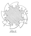
- each roll assembly 1, 2 has a body provided with a number of longitudinally disposed parallel dovetail-like grooves 6, and tooth bearing members 12 are formed with dovetail-like projections 7 to fit in the grooves 6.
- the teeth are so formed and located on the rolls that those on the roll face 1 face those on the roll 2, and such that when the rolls are located in the machine and caused to rotate, the teeth will grip and crush material falling into the nip of the rolls.
- each roll assembly 1, 2 a plurality of individual tooth bearing segments are provided, disposed side-by-side in rows along the grooves 6. As seen in cross-section in Figure 2, there are eight rows 6, and eight segments 12, spaced equally at 45° intervals around the periphery of each roll assembly 1, 2.
- Each segment 12 is formed with an integral tooth 11, or indeed more than one tooth if so required, and each segment 12 is formed with a respective dovetail-like projection 7 to fit in respective ones of the dovetail-like grooves in the roll body surface.
- an abutment plate 9 secured at one end of the roll body, the requisite number of segments 12 can be slid onto the roll body from the opposite end, and another abutment plate 10 secured to the roll body to hold the segments 12 in position.
- each abutment plate 9, 10 may be secured to the end face of the roll body by means of screws which engage apertures in the roll body.
- the abutment plate 9 may, if desired, be fixed, and the plate 10 removable.
- the apparatus illustrated in Figures 1 and 2 provides for the replacement of the teeth of the roll assemblies considerably more simply and with drastically reduced down time of the machine, in comparison with the prior art, such that segments with worn or damaged teeth may be replaced by new segments, with the roll assemblies in situ.
- the abutment plate 10 may be released, and slid along the shaft by a distance at least equal to the width of each segment 12.
- the segments 12 can be slid along the roll body into the gap between the roll body and the plate 10, and then removed for replacement, radially of the roll assembly 1, 2.
- each half-ring may be removed radially of the roll assembly 1, 2, after release from the end face of the roll body.
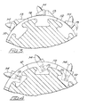
- each segment 12 may have secured to its outer periphery a relatively conventional pick-box 13 in which a point-attack pick 14 is located.
- a still further alternative is shown where the segment 12 itself serves as the pick-box, by being formed with an appropriately shaped bore 15 angularly disposed within the segment 12 and in which the pick 14 can be located.
- each roll body is formed by a shaft 16 and a number of drum-like annuli 17 adapted to fit the shaft 16, each annulus at its periphery being formed with a number of parallel dovetail-like slots 6 to receive a number of segments 12, each provided with a corresponding dovetail-like projection 7.
- each annulus is formed with a keyway slot 19 to locate it on the shaft 16 and by strategically positioning each keyway slot 19 on the number of annuli involved, adjacent annuli can be set on the shaft such that the teeth on the segments on the adjacent annuli are offset.
- the offsetting can be set to provide straight rows of teeth at any required angular disposition in relation to the shaft axis, to provide rows of teeth that are helically disposed along the length of the roll, or if desired, to provide a random distribution of teeth.
- the individual annuli 17 may be moved their own length along the shaft 16, after removal of the abutment plate 10, to enable a gap to be formed between any two adjacent annuli 17, to allow the removal and replacement of tooth bearing segments 12, without disconnecting the roll assembly from its bearings.
- wear plates 8 which are detachably secured to the housing, to cover the clearance space between the respective end of the roll bodies and the housing, and therefore prevent oversized debris from falling through this clearance space, whilst the machine is working.
- the wear plates 8 are firstly removed.
- tooth bearing segments 12 are of substantially the same width as the annuli 17.
- each section shows eight tooth bearing segments 12 at 45° intervals
- alternative configurations of tooth bearing segments may be provided.
- two tooth bearing segments each subtending an angle of 180°, and each having four projections 7 to fit the four corresponding grooves 6 in the respective roll body.
- Each roll body may be formed by casting. Alternatively or additionally, the grooves 6 may be formed by suitable machining. Each roll body may be of a suitably tough material such as mild steel, keyed to a suitable, relatively small diameter, alloy shaft.
- the tooth bearing members 12 are preferably cast from a hard wearing and impact resistant tool steel, such as manganese steel.
Landscapes
- Engineering & Computer Science (AREA)
- Food Science & Technology (AREA)
- Crushing And Grinding (AREA)
Claims (24)
Applications Claiming Priority (4)
| Application Number | Priority Date | Filing Date | Title |
|---|---|---|---|
| GB8233900 | 1982-11-27 | ||
| GB8233900 | 1982-11-27 | ||
| GB8314967 | 1983-05-31 | ||
| GB838314967A GB8314967D0 (en) | 1983-05-31 | 1983-05-31 | Comminuting apparatus |
Publications (3)
| Publication Number | Publication Date |
|---|---|
| EP0110665A2 EP0110665A2 (fr) | 1984-06-13 |
| EP0110665A3 EP0110665A3 (en) | 1985-09-11 |
| EP0110665B1 true EP0110665B1 (fr) | 1987-06-10 |
Family
ID=26284515
Family Applications (1)
| Application Number | Title | Priority Date | Filing Date |
|---|---|---|---|
| EP19830307148 Expired EP0110665B1 (fr) | 1982-11-27 | 1983-11-23 | Appareil broyeur |
Country Status (2)
| Country | Link |
|---|---|
| EP (1) | EP0110665B1 (fr) |
| DE (1) | DE3371966D1 (fr) |
Cited By (2)
| Publication number | Priority date | Publication date | Assignee | Title |
|---|---|---|---|---|
| CN103127980A (zh) * | 2011-11-23 | 2013-06-05 | 新乡市高服筛分机械有限公司 | 一种破碎机齿辊 |
| CN103372477A (zh) * | 2012-11-23 | 2013-10-30 | 无锡众望四维科技有限公司 | 破碎辊 |
Families Citing this family (19)
| Publication number | Priority date | Publication date | Assignee | Title |
|---|---|---|---|---|
| DE3336827A1 (de) * | 1983-10-10 | 1985-04-25 | Claudius Peters Ag, 2000 Hamburg | Brechwalze fuer walzenbrecher |
| GB8612202D0 (en) * | 1986-03-20 | 1986-06-25 | Mmd Design & Consult | Mineral breaker |
| AU2620988A (en) * | 1987-11-17 | 1989-06-14 | Extec Screens And Crushers Limited | Rotary crusher |
| DE4123967A1 (de) * | 1991-07-19 | 1993-01-21 | Krupp Industrietech | Zweiwalzenbrecher mit auswechselbaren brechzaehnen |
| DE4432038A1 (de) * | 1994-09-09 | 1996-03-14 | Basf Ag | Polyetheramine enthaltende Kraftstoffe für Ottomotoren |
| AT403443B (de) * | 1995-07-11 | 1998-02-25 | Enco En Componenten Ges M B H | Einrichtung zum zerkleinern harter materialien, vorzugsweise biogener abfälle |
| DE20108463U1 (de) | 2000-11-30 | 2001-10-25 | Schenk, Jürgen, 70188 Stuttgart | Vorrichtung zur Aufbereitung von Aushub |
| AUPR271201A0 (en) * | 2001-01-25 | 2001-02-22 | Abon Engineering Pty Ltd | Apparatus for crushing material |
| AU762265B2 (en) * | 2001-01-25 | 2003-06-19 | Flsmidth Abon Pty Ltd | Apparatus for crushing material |
| FR2943630B1 (fr) * | 2009-03-30 | 2016-06-24 | Soc D'etudes Et De Rech De L'ecole Nat Superieure D'arts Et Metiers (Seram) | Dispositif d'extraction de liquide contenu dans des recipients en materiau non cassant |
| DE102013207092A1 (de) * | 2013-04-19 | 2014-10-23 | Takraf Gmbh | Brechwalze für einen Walzenbrecher |
| DE102015206957B3 (de) * | 2015-04-17 | 2016-09-08 | Takraf Gmbh | Brechwalze für einen Brecher |
| CN107138214B (zh) * | 2017-07-18 | 2019-04-26 | 湖北神东建设有限公司 | 一种用于建筑废料的木质板材破碎回收装置 |
| CN107716057B (zh) * | 2017-10-14 | 2020-08-21 | 佛山海格利德机器人智能设备有限公司 | 一种全自动智能管道破碎设备 |
| CN108160289B (zh) * | 2017-12-25 | 2019-12-10 | 山西华正创新技术研究院有限公司 | 一种建筑垃圾高效破碎装置 |
| CN108465514A (zh) * | 2018-05-30 | 2018-08-31 | 福建铁拓机械有限公司 | 一种具有改进齿板连接结构的废旧沥青混合料破碎辊 |
| CN112934343B (zh) * | 2021-01-21 | 2022-05-10 | 中信重工机械股份有限公司 | 一种嵌入齿式拱形破碎棒装置 |
| WO2024082030A1 (fr) * | 2022-10-21 | 2024-04-25 | Prestige Trading Co. Pty Ltd | Ensemble de broyage |
| CN117105657B (zh) * | 2023-09-18 | 2024-05-07 | 深圳市华辰新材料科技有限公司 | 纳米级钛酸镧的低温烧结制备方法及设备 |
Family Cites Families (9)
| Publication number | Priority date | Publication date | Assignee | Title |
|---|---|---|---|---|
| FR319015A (fr) * | 1902-02-24 | 1902-10-31 | Mason Junior | Perfectionnements apportés à la fabrication des coussinets de machines ou autres et s'appliquant plus particulièrement aux tetes ou rouleaux à broyer ou moudre |
| GB469343A (en) * | 1936-03-27 | 1937-07-23 | Sydney Moore Milbourne | Improvements in or relating to apparatus for breaking or cutting coke, coal and like substances |
| DE1221081B (de) * | 1960-12-15 | 1966-07-14 | Schuechtermann & Kremer | Walze fuer Walzenbrecher |
| US4042183A (en) * | 1976-04-21 | 1977-08-16 | Cumpston Edward H | Rotor for mixer-refiner-reactor |
| GB1558423A (en) * | 1978-03-03 | 1980-01-03 | Dresser Europe Sa | Shredding machine |
| US4219291A (en) * | 1979-03-14 | 1980-08-26 | Hoeh James A | Segmented helical rotary cutter and method of making same |
| DE2936351C2 (de) * | 1979-09-08 | 1982-09-16 | PHB Weserhütte AG, 5000 Köln | Brechwalze für Walzenbrecher |
| GB2110954B (en) * | 1981-12-05 | 1984-10-10 | Dresser Europe Sa | Tool-holding mounting ring for crushing machine rotor |
| ZA831380B (en) * | 1982-03-09 | 1983-11-30 | Mmd Design & Consult | Mineral sizer |
-
1983
- 1983-11-23 EP EP19830307148 patent/EP0110665B1/fr not_active Expired
- 1983-11-23 DE DE8383307148T patent/DE3371966D1/de not_active Expired
Cited By (2)
| Publication number | Priority date | Publication date | Assignee | Title |
|---|---|---|---|---|
| CN103127980A (zh) * | 2011-11-23 | 2013-06-05 | 新乡市高服筛分机械有限公司 | 一种破碎机齿辊 |
| CN103372477A (zh) * | 2012-11-23 | 2013-10-30 | 无锡众望四维科技有限公司 | 破碎辊 |
Also Published As
| Publication number | Publication date |
|---|---|
| EP0110665A2 (fr) | 1984-06-13 |
| EP0110665A3 (en) | 1985-09-11 |
| DE3371966D1 (de) | 1987-07-16 |
Similar Documents
| Publication | Publication Date | Title |
|---|---|---|
| EP0110665B1 (fr) | Appareil broyeur | |
| US7055770B2 (en) | Reducing machine rotor assembly and methods of constructing and operating the same | |
| US4406415A (en) | Rotor assembly for hammermills | |
| CA2346603C (fr) | Assemblage rotor ameliore pour tour a reduire, et methodes de construction et d'operation dudit rotor | |
| US11794194B2 (en) | Shredder blade assembly | |
| US5680999A (en) | Shredder | |
| US6343755B1 (en) | Tire shredding machinery | |
| WO2000050173A1 (fr) | Marteau a fente, destine a un broyeur a marteaux | |
| SK281237B6 (sk) | Drvička s rotorom | |
| CA1165295A (fr) | Machoires et dispositif de reglage pour broyeur | |
| US7100855B2 (en) | Modular blades for tire shredder | |
| US20050116075A1 (en) | Crushing device | |
| DE3802260C2 (fr) | ||
| CA1114799A (fr) | Garniture de chemisage pour broyeur de minerai | |
| US5580010A (en) | Cutting segments with interlock key assembly for a rotary shearing wheel | |
| US2585943A (en) | Impact rotor for stone breakers | |
| US5833153A (en) | Rotor assembly for horizontal impact crusher | |
| EP0246775A2 (fr) | Broyeur pour minerais | |
| EP0873791A2 (fr) | Rotor pour déchiqueteurs et broyeurs à marteaux | |
| WO1989004719A1 (fr) | Broyeur rotatif | |
| US4635863A (en) | Reversible, axially fed, cage rotor impact breaker | |
| WO2017007449A1 (fr) | Ensemble lame de déchiqueteuse | |
| US20240082849A1 (en) | Roller crusher and a method for operating the same | |
| GB2142675A (en) | Drum assembly | |
| GB2221629A (en) | Crushing machine with protective shields |
Legal Events
| Date | Code | Title | Description |
|---|---|---|---|
| PUAI | Public reference made under article 153(3) epc to a published international application that has entered the european phase |
Free format text: ORIGINAL CODE: 0009012 |
|
| AK | Designated contracting states |
Designated state(s): DE FR GB SE |
|
| PUAL | Search report despatched |
Free format text: ORIGINAL CODE: 0009013 |
|
| AK | Designated contracting states |
Designated state(s): DE FR GB SE |
|
| 17P | Request for examination filed |
Effective date: 19850805 |
|
| 17Q | First examination report despatched |
Effective date: 19860306 |
|
| R17C | First examination report despatched (corrected) |
Effective date: 19860812 |
|
| GRAA | (expected) grant |
Free format text: ORIGINAL CODE: 0009210 |
|
| AK | Designated contracting states |
Kind code of ref document: B1 Designated state(s): DE FR GB SE |
|
| REF | Corresponds to: |
Ref document number: 3371966 Country of ref document: DE Date of ref document: 19870716 |
|
| ET | Fr: translation filed | ||
| PLBE | No opposition filed within time limit |
Free format text: ORIGINAL CODE: 0009261 |
|
| STAA | Information on the status of an ep patent application or granted ep patent |
Free format text: STATUS: NO OPPOSITION FILED WITHIN TIME LIMIT |
|
| 26N | No opposition filed | ||
| EAL | Se: european patent in force in sweden |
Ref document number: 83307148.3 |
|
| PGFP | Annual fee paid to national office [announced via postgrant information from national office to epo] |
Ref country code: SE Payment date: 20001120 Year of fee payment: 18 |
|
| PGFP | Annual fee paid to national office [announced via postgrant information from national office to epo] |
Ref country code: FR Payment date: 20001127 Year of fee payment: 18 |
|
| PGFP | Annual fee paid to national office [announced via postgrant information from national office to epo] |
Ref country code: DE Payment date: 20001228 Year of fee payment: 18 |
|
| PG25 | Lapsed in a contracting state [announced via postgrant information from national office to epo] |
Ref country code: SE Free format text: LAPSE BECAUSE OF NON-PAYMENT OF DUE FEES Effective date: 20011124 |
|
| REG | Reference to a national code |
Ref country code: GB Ref legal event code: IF02 |
|
| EUG | Se: european patent has lapsed |
Ref document number: 83307148.3 |
|
| PG25 | Lapsed in a contracting state [announced via postgrant information from national office to epo] |
Ref country code: DE Free format text: LAPSE BECAUSE OF NON-PAYMENT OF DUE FEES Effective date: 20020702 |
|
| PG25 | Lapsed in a contracting state [announced via postgrant information from national office to epo] |
Ref country code: FR Free format text: LAPSE BECAUSE OF NON-PAYMENT OF DUE FEES Effective date: 20020730 |
|
| REG | Reference to a national code |
Ref country code: FR Ref legal event code: ST |
|
| REG | Reference to a national code |
Ref country code: FR Ref legal event code: ST |
|
| PGFP | Annual fee paid to national office [announced via postgrant information from national office to epo] |
Ref country code: GB Payment date: 20021125 Year of fee payment: 20 |
|
| PG25 | Lapsed in a contracting state [announced via postgrant information from national office to epo] |
Ref country code: GB Free format text: LAPSE BECAUSE OF EXPIRATION OF PROTECTION Effective date: 20031122 |
|
| REG | Reference to a national code |
Ref country code: GB Ref legal event code: PE20 |