EP0109908B1 - Verfahren zum Formen eines Verkleidungselements für Dächer oder Fassaden und das so hergestellte Verkleidungselement - Google Patents
Verfahren zum Formen eines Verkleidungselements für Dächer oder Fassaden und das so hergestellte Verkleidungselement Download PDFInfo
- Publication number
- EP0109908B1 EP0109908B1 EP19830402234 EP83402234A EP0109908B1 EP 0109908 B1 EP0109908 B1 EP 0109908B1 EP 19830402234 EP19830402234 EP 19830402234 EP 83402234 A EP83402234 A EP 83402234A EP 0109908 B1 EP0109908 B1 EP 0109908B1
- Authority
- EP
- European Patent Office
- Prior art keywords
- mold
- lateral
- longitudinal
- imprints
- fact
- Prior art date
- Legal status (The legal status is an assumption and is not a legal conclusion. Google has not performed a legal analysis and makes no representation as to the accuracy of the status listed.)
- Expired
Links
Images

Classifications
-
- E—FIXED CONSTRUCTIONS
- E04—BUILDING
- E04D—ROOF COVERINGS; SKY-LIGHTS; GUTTERS; ROOF-WORKING TOOLS
- E04D3/00—Roof covering by making use of flat or curved slabs or stiff sheets
- E04D3/24—Roof covering by making use of flat or curved slabs or stiff sheets with special cross-section, e.g. with corrugations on both sides, with ribs, flanges, or the like
- E04D3/32—Roof covering by making use of flat or curved slabs or stiff sheets with special cross-section, e.g. with corrugations on both sides, with ribs, flanges, or the like of plastics, fibrous materials, or asbestos cement
-
- B—PERFORMING OPERATIONS; TRANSPORTING
- B29—WORKING OF PLASTICS; WORKING OF SUBSTANCES IN A PLASTIC STATE IN GENERAL
- B29C—SHAPING OR JOINING OF PLASTICS; SHAPING OF MATERIAL IN A PLASTIC STATE, NOT OTHERWISE PROVIDED FOR; AFTER-TREATMENT OF THE SHAPED PRODUCTS, e.g. REPAIRING
- B29C37/00—Component parts, details, accessories or auxiliary operations, not covered by group B29C33/00 or B29C35/00
- B29C37/0053—Moulding articles characterised by the shape of the surface, e.g. ribs, high polish
-
- B—PERFORMING OPERATIONS; TRANSPORTING
- B29—WORKING OF PLASTICS; WORKING OF SUBSTANCES IN A PLASTIC STATE IN GENERAL
- B29C—SHAPING OR JOINING OF PLASTICS; SHAPING OF MATERIAL IN A PLASTIC STATE, NOT OTHERWISE PROVIDED FOR; AFTER-TREATMENT OF THE SHAPED PRODUCTS, e.g. REPAIRING
- B29C67/00—Shaping techniques not covered by groups B29C39/00 - B29C65/00, B29C70/00 or B29C73/00
- B29C67/24—Shaping techniques not covered by groups B29C39/00 - B29C65/00, B29C70/00 or B29C73/00 characterised by the choice of material
- B29C67/242—Moulding mineral aggregates bonded with resin, e.g. resin concrete
- B29C67/243—Moulding mineral aggregates bonded with resin, e.g. resin concrete for making articles of definite length
-
- E—FIXED CONSTRUCTIONS
- E04—BUILDING
- E04F—FINISHING WORK ON BUILDINGS, e.g. STAIRS, FLOORS
- E04F13/00—Coverings or linings, e.g. for walls or ceilings
- E04F13/07—Coverings or linings, e.g. for walls or ceilings composed of covering or lining elements; Sub-structures therefor; Fastening means therefor
- E04F13/08—Coverings or linings, e.g. for walls or ceilings composed of covering or lining elements; Sub-structures therefor; Fastening means therefor composed of a plurality of similar covering or lining elements
- E04F13/0864—Coverings or linings, e.g. for walls or ceilings composed of covering or lining elements; Sub-structures therefor; Fastening means therefor composed of a plurality of similar covering or lining elements composed of superposed elements which overlap each other and of which the flat outer surface includes an acute angle with the surface to cover
-
- B—PERFORMING OPERATIONS; TRANSPORTING
- B29—WORKING OF PLASTICS; WORKING OF SUBSTANCES IN A PLASTIC STATE IN GENERAL
- B29C—SHAPING OR JOINING OF PLASTICS; SHAPING OF MATERIAL IN A PLASTIC STATE, NOT OTHERWISE PROVIDED FOR; AFTER-TREATMENT OF THE SHAPED PRODUCTS, e.g. REPAIRING
- B29C39/00—Shaping by casting, i.e. introducing the moulding material into a mould or between confining surfaces without significant moulding pressure; Apparatus therefor
- B29C39/02—Shaping by casting, i.e. introducing the moulding material into a mould or between confining surfaces without significant moulding pressure; Apparatus therefor for making articles of definite length, i.e. discrete articles
-
- B—PERFORMING OPERATIONS; TRANSPORTING
- B29—WORKING OF PLASTICS; WORKING OF SUBSTANCES IN A PLASTIC STATE IN GENERAL
- B29C—SHAPING OR JOINING OF PLASTICS; SHAPING OF MATERIAL IN A PLASTIC STATE, NOT OTHERWISE PROVIDED FOR; AFTER-TREATMENT OF THE SHAPED PRODUCTS, e.g. REPAIRING
- B29C41/00—Shaping by coating a mould, core or other substrate, i.e. by depositing material and stripping-off the shaped article; Apparatus therefor
- B29C41/02—Shaping by coating a mould, core or other substrate, i.e. by depositing material and stripping-off the shaped article; Apparatus therefor for making articles of definite length, i.e. discrete articles
- B29C41/08—Coating a former, core or other substrate by spraying or fluidisation, e.g. spraying powder
-
- B—PERFORMING OPERATIONS; TRANSPORTING
- B29—WORKING OF PLASTICS; WORKING OF SUBSTANCES IN A PLASTIC STATE IN GENERAL
- B29K—INDEXING SCHEME ASSOCIATED WITH SUBCLASSES B29B, B29C OR B29D, RELATING TO MOULDING MATERIALS OR TO MATERIALS FOR MOULDS, REINFORCEMENTS, FILLERS OR PREFORMED PARTS, e.g. INSERTS
- B29K2105/00—Condition, form or state of moulded material or of the material to be shaped
- B29K2105/06—Condition, form or state of moulded material or of the material to be shaped containing reinforcements, fillers or inserts
- B29K2105/12—Condition, form or state of moulded material or of the material to be shaped containing reinforcements, fillers or inserts of short lengths, e.g. chopped filaments, staple fibres or bristles
-
- B—PERFORMING OPERATIONS; TRANSPORTING
- B29—WORKING OF PLASTICS; WORKING OF SUBSTANCES IN A PLASTIC STATE IN GENERAL
- B29K—INDEXING SCHEME ASSOCIATED WITH SUBCLASSES B29B, B29C OR B29D, RELATING TO MOULDING MATERIALS OR TO MATERIALS FOR MOULDS, REINFORCEMENTS, FILLERS OR PREFORMED PARTS, e.g. INSERTS
- B29K2503/00—Use of resin-bonded materials as filler
- B29K2503/04—Inorganic materials
- B29K2503/08—Mineral aggregates, e.g. sand, clay or the like
-
- B—PERFORMING OPERATIONS; TRANSPORTING
- B29—WORKING OF PLASTICS; WORKING OF SUBSTANCES IN A PLASTIC STATE IN GENERAL
- B29L—INDEXING SCHEME ASSOCIATED WITH SUBCLASS B29C, RELATING TO PARTICULAR ARTICLES
- B29L2031/00—Other particular articles
- B29L2031/10—Building elements, e.g. bricks, blocks, tiles, panels, posts, beams
Definitions
- the present invention relates to modules for covering roofs and facades, which consist of molded parts imitating by imprints several successive rows of traditional elements, such as slates, tiles, stones or other facing materials.
- Such molded parts are large or medium-sized modules, which by assembly very faithfully reconstruct a roof, for example thick slates mounted in the old way or cladding elements.
- the author of the present invention was aware of a molding process by casting or projection of a module for covering roofs and facades constituted by a molded part imitating by imprints several successive rows of 'elements, such as slates, tiles, stones or other facing materials, the elements of a row being offset horizontally relative to the elements of the adjacent row, able to be assembled with the adjacent modules by superimposition of the edges provided with edges or cheeks of reduced thickness compared to that of the central part of the module provided with imprints.
- the mold used according to this technique included a central part provided with imprints bordered by a longitudinal strip and a side strip with raised bottoms.
- a module was obtained consisting of a molded part imitating by imprints several successive rows of elements, such as slates, tiles, stones or other facing materials.
- the object of the present invention is to perfect such a technique and, in particular, to obtain covering modules having accountabilitys, during assembly, and the manufacture of which does not require countermolding.
- the subject of the invention is a molding process by casting or by projection, optionally with simultaneous projection of fibers, of a module for covering roofs and facades constituted by a molded part imitating by imprints several successive rows of elements, such as slates, tiles, stones or other facing materials, the elements of a row being offset horizontally relative to the elements of the adjacent row, able to be assembled with the adjacent modules by superimposition of the edges provided with thick edges or cheeks reduced compared to that of the central part of the module fitted with imprints.
- thermosetting resin containing fillers is filled with a mold to the brim, the central part of which is provided with imprints in negative relief is bordered by two bands with a raised bottom, one on the longitudinal side and the other on the lateral side, the level of the mold thus filled is leveled by means of an appropriate tool, such as a roller, crimper or other, it is sprayed over the entire extent of the mold short glass fibers impregnated with resin and the mold is baked until the resin hardens.
- an appropriate tool such as a roller, crimper or other
- the entire surface of the mold is first coated with a gel-coat.
- the air bubbles included in the mass are removed, for example by means of grooved rollers.
- composition of the resin mixture can vary between wide limits, for example between 5 and 60% of resin, the remainder consisting of mineral fillers and glass fibers.
- polyester resin Preferably, a mixture of 40% polyester resin and 60% mineral fillers will be used.
- Other resins such as phenolic, furan and epoxy resins are also suitable.
- the invention also relates to a mold suitable for the implementation of such a method and which comprises a central part provided with imprints bordered by a longitudinal strip and a side strip with raised bottoms, characterized in that the upper face of the side wall bordering the mold lies in two different planes, the side wall bordering the side strip having a height greater than that of the remaining wall of the mold and in that the bottom of the longitudinal strip is against low with respect to the bottom of the side strip, so that the filling depth of the two strips is substantially the same and, however, the volume of the side strip is vertically offset from that of the longitudinal strip.
- the mold preferably has indentations in the lateral and longitudinal edges intended to form orifices for the nailing of the module on a liteaunage.
- the bottom of the lateral strip of the mold has a series of parallel longitudinal imprints to facilitate the flow of water.
- the invention also relates to the module for covering roofs and facades obtained by application of the method using the aforementioned mold and constituted by a molded part imitating by imprints several successive rows of elements, such as slates, tiles, stones or other facing materials, which module is characterized in that it has two edges or cheeks, one longitudinal for the longitudinal assembly of the modules and the other lateral for the lateral assembly of the modules, the two edges being formed by thin blades of substantially equal thickness, the lateral edge being offset below against the longitudinal edge and relative to the plane of the internal face of the mold, the offset between the two planes being of the order of 1 thickness of a border.
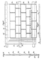
- the mold shown in Figures 1,2 and 3 is constituted by a bottom 1 whose central part is provided with imprints of the five rows 1a, 1b, 1c, 1d and 1e of slate.
- On its two sides are represented two bands for the formation of the edges of the module used to assemble the modules together, and in particular band 2 for the formation of the longitudinal edge used for the assembly of the modules in the direction of the slope of the roof and the strip 3 for the formation of the lateral border used for the lateral assembly of the modules.
- the bottom 1 is bordered by side walls of the mold, in particular the walls 5 bordering the entire periphery of the mold with the exception of the strip 3, the walls 6 of which are higher than the walls 5.
- the bottom of the strip 3 is raised relative to that of the strip 2 and in particular of the thickness of a border. This difference in level is represented by line 7.
- the filling heights of the strips 2 and 3 are substantially equal, but the plane of the strip 2 is offset below that of the strip 3.
- the two borders keeping the same thickness and the value of the offset will be the thickness of a border.
- the lateral strip 3 has imprints of longitudinal grooves 14a.
- the mold has indentations or inserts 8 distributed along the strips 2 and 3.
- a mold was chosen whose part provided with imprints measures 1/3 m 2 , the width of the strips 2 and 3 being 120 mm and their filling depth, as well as the offset between the plane of the strip 3 and that of the strip 2, being approximately 2 mm.
- the mold can be of any material, for example plastic or elastomer.
- an aluminum mold will be used, which is particularly advantageous because of its resistance to wear and fidelity of reproduction of the relief.
- the mixture used contains 40% of polyester resin, the filler being constituted by fine mineral particles, such as sand, slate or brick powder and short fibers or glass fiber mats.
- the first operation consists in coating the entire surface of the mold with gel-coat. Then, the mold is spray-filled with the mixture of resin and fillers and the level of filling of the mold is equalized by means of a strip. The bubbling is carried out by means of grooved rollers.
- the last operation consists in spraying on the surface short glass fibers impregnated with resin. Cooking takes place in a tunnel oven at a temperature between 60 and 90 ° C.
- the module obtained represented in FIGS. 5, 6 and 7 comprises a central part provided with impressions imitating successive rows of slates 10a, 10b, 10c, 10d and 10e, in each row the slates being delimited by grooves 12. View of profile, each slate has a raised nose at its front and a heel ending the slope.
- the modules are assembled by superimposing the edges 20 and 30.
- the row 10e of a module will cover the longitudinal edge 20 of the adjacent module.
- the edge 20 ′ of a thickness of approximately 2 mm, adjacent to the last row 10a ′ of a neighboring module, is covered by the row 10e of the module.
- the heel 11 of the slates of this last row 10a ′ will be slightly raised relative to the heels of the other rows of the same module, so as to make the junction line of the two modules invisible.
- the edge 30, provided with grooves 14 to facilitate the flow of water, being offset below against the plane of the internal face of the mold, and in particular the plane of that slates at the ends of the neighboring module, no excess thickness at the junction will be visible and the assembly will give the homogeneous appearance of a slate roof laid in the old way.
- the battens shown in 13 will serve as fastenings by nailing the modules at the location of the orifices 80 made during molding.
- a good longitudinal assembly of modules can be favored by the installation during molding of a profiled strip 15, which anchored by one of its ends in the mass on the back of the central part of the module, for example at the height of row 10d, the longitudinal edge 20 ′ of the adjacent module will pinch over approximately two thirds of its length, on which the last row 10e of the module shown rests.
- the invention is of particular interest because of its realization without the use of a counter-mold. , matrix or other means of making an impression on the back of the module.
- Producing a back of the module in the form of two planes offset from each other by a thickness of border does not require any. This procedure avoids large investments in equipment.
- a simple leveling roller makes it possible to produce such a rear face of the module composed of the two flat faces. Only the offset, as produced, allows, while doing without a counter-mold, to use borders at the time of assembly without creating apparent discontinuities.
- the invention is not limited to the embodiment described, it can take other forms, in particular as regards the geometric shape of modules, the shape and arrangement of the impressions imitating the various facing materials or their means fixing and assembly.
Landscapes
- Engineering & Computer Science (AREA)
- Structural Engineering (AREA)
- Architecture (AREA)
- Civil Engineering (AREA)
- Ceramic Engineering (AREA)
- Mechanical Engineering (AREA)
- Finishing Walls (AREA)
- Roof Covering Using Slabs Or Stiff Sheets (AREA)
- Casting Or Compression Moulding Of Plastics Or The Like (AREA)
Claims (10)
Applications Claiming Priority (2)
| Application Number | Priority Date | Filing Date | Title |
|---|---|---|---|
| FR8219488A FR2536332B1 (fr) | 1982-11-22 | 1982-11-22 | Procede de moulage de module de recouvrement de toits et de facades et le module ainsi obtenu |
| FR8219488 | 1982-11-22 |
Publications (3)
| Publication Number | Publication Date |
|---|---|
| EP0109908A2 EP0109908A2 (de) | 1984-05-30 |
| EP0109908A3 EP0109908A3 (en) | 1986-07-30 |
| EP0109908B1 true EP0109908B1 (de) | 1988-03-02 |
Family
ID=9279375
Family Applications (1)
| Application Number | Title | Priority Date | Filing Date |
|---|---|---|---|
| EP19830402234 Expired EP0109908B1 (de) | 1982-11-22 | 1983-11-21 | Verfahren zum Formen eines Verkleidungselements für Dächer oder Fassaden und das so hergestellte Verkleidungselement |
Country Status (5)
| Country | Link |
|---|---|
| EP (1) | EP0109908B1 (de) |
| CA (1) | CA1220311A (de) |
| DE (1) | DE3375765D1 (de) |
| ES (1) | ES287925Y (de) |
| FR (1) | FR2536332B1 (de) |
Families Citing this family (3)
| Publication number | Priority date | Publication date | Assignee | Title |
|---|---|---|---|---|
| GB2225275B (en) * | 1989-02-04 | 1991-05-08 | Meirion Gribble | Slate-filled resin products |
| FR2654035B1 (fr) * | 1989-11-07 | 1993-04-30 | Caruso Philippe | Procede de realisation de plaques de parement de facades ou de revetement de sols, ou autres, en matiere synthetique, dispositif pour la mise en óoeuvre de ce procede et plaque ainsi obtenue. |
| ES2148027B1 (es) * | 1997-04-15 | 2001-06-01 | Maquinaria Jumilla S L | Pieza para la formacion de tejados y cubiertas de edificaciones. |
Family Cites Families (12)
| Publication number | Priority date | Publication date | Assignee | Title |
|---|---|---|---|---|
| LU42767A1 (de) * | 1962-04-21 | 1963-01-28 | ||
| US3312761A (en) * | 1963-03-07 | 1967-04-04 | Vida Alex | Method of making building facing material |
| FR1508556A (fr) * | 1966-01-29 | 1968-01-05 | Perfectionnements apportés au procédé de fabrication de matériaux de construction | |
| CH507882A (de) * | 1967-12-06 | 1971-05-31 | Repla Sa | Verfahren zur Herstellung kunstharzgebundener Platten |
| GB1261196A (en) * | 1968-07-25 | 1972-01-26 | Robertson Co H H | Improvements in or relating to panels for building construction |
| FR2028689A1 (de) * | 1969-01-23 | 1970-10-16 | Wegrzyn Jean | |
| FR2079515A5 (de) * | 1970-02-04 | 1971-11-12 | Soquet Marc | |
| GB1404934A (en) * | 1971-07-16 | 1975-09-03 | Zacaroli H L | Decorative tiles and methods of making them |
| FR2242148B1 (de) * | 1973-08-31 | 1983-08-05 | Carcel Jean Louis | |
| US4343126A (en) * | 1979-02-26 | 1982-08-10 | Hoofe Iii William J | Interlocking panels |
| FR2502669B2 (fr) * | 1980-04-16 | 1986-04-25 | Beauchamp Michel | Element prefabrique pour la construction de panneaux de recouvrement, notamment pour toiture |
| FR2522348B1 (fr) * | 1982-03-01 | 1986-01-10 | Roger Biraben | Module pour recouvrement de toits ou de facades |
-
1982
- 1982-11-22 FR FR8219488A patent/FR2536332B1/fr not_active Expired
-
1983
- 1983-11-21 EP EP19830402234 patent/EP0109908B1/de not_active Expired
- 1983-11-21 CA CA000441579A patent/CA1220311A/fr not_active Expired
- 1983-11-21 DE DE8383402234T patent/DE3375765D1/de not_active Expired
- 1983-11-22 ES ES1983287925U patent/ES287925Y/es not_active Expired
Also Published As
| Publication number | Publication date |
|---|---|
| EP0109908A2 (de) | 1984-05-30 |
| DE3375765D1 (en) | 1988-04-07 |
| ES287925U (es) | 1985-11-16 |
| FR2536332B1 (fr) | 1985-07-12 |
| FR2536332A1 (fr) | 1984-05-25 |
| ES287925Y (es) | 1986-06-16 |
| EP0109908A3 (en) | 1986-07-30 |
| CA1220311A (fr) | 1987-04-14 |
Similar Documents
| Publication | Publication Date | Title |
|---|---|---|
| EP0122210B1 (de) | Glaselement, insbesondere Ziegel- oder Pflasterstein | |
| EP0109908B1 (de) | Verfahren zum Formen eines Verkleidungselements für Dächer oder Fassaden und das so hergestellte Verkleidungselement | |
| EP0141453B1 (de) | Vorgefertigte Wandverkleidungsplatte, Herstellungsverfahren und Verwendung | |
| FR2491115A1 (fr) | Procede d'assemblage et de decoffrage de coffrages de plancher pour travaux de betonnage et coffrage de plancher pour la mise en oeuvre du procede | |
| FR2845714A1 (fr) | Module d'assemblage pour revetements de sols ou murs | |
| EP0360682B1 (de) | Dehnungsfuge für Betonbodenbelag | |
| EP0262712B1 (de) | Bauelement | |
| EP0285509B1 (de) | Baukonstruktionselemente, insbesondere für Bedachung und/oder Einkleidung und Verfahren zu deren Befestigung auf einer tiefer liegenden Stütze | |
| EP0113290A1 (de) | Verkleidungselemente zur Durchführung der thermischen Isolation auf der Aussenseite von Gebäuden | |
| EP0726369A1 (de) | Formbaustein aus Ton und Verfahren zu seiner Herstellung | |
| FR2546560A1 (fr) | Panneaux pour le revetement de la face externe de parois de batiments | |
| FR2479310A1 (fr) | Plaque de recouvrement de toit | |
| FR2731737A1 (fr) | Element de revetement, notamment de parquet, pret a l'emploi | |
| FR2546440A1 (fr) | Coffrage en bois pour l'execution de volees droites d'escaliers en beton | |
| EP0224012A2 (de) | Verfahren zum Herstellen von Wänden für Bauelemente und Gebäude und Baublöcke für dieses Verfahren | |
| EP0145579A2 (de) | Verglasungen, durch Profile ohne Glaserkitt unterstützt | |
| FR2589504A1 (fr) | Element de parement utilisable pour constituer une peau d'etancheite pour supports du type facades ou pignons d'immeuble et peau d'etancheite constituee de tels elements montes sur le support par l'intermediaire d'un rail | |
| FR2492435A1 (fr) | Panneau prefabrique pour bassins, procede de fabrication et procede de mise en place | |
| EP1451424B1 (de) | Kunststeinverkleidung | |
| FR2522348A1 (fr) | Module pour recouvrement de toits ou de facades | |
| WO2002101174A1 (fr) | Parement de pierres artificielles et de dalles elementaires de facade et d'angle pour sa realisation | |
| BE691474A (de) | ||
| FR2557831A1 (fr) | Procede et dispositif de moulage pour la fabrication de panneaux de revetement de plafonds et de murs et panneau obtenu | |
| FR2516571A1 (fr) | Dispositif et procede pour la formation d'un joint de dilatation et d'etancheite | |
| FR2986809A1 (fr) | Bloc de construction a portion ajustee, procede de fabrication et ouvrage obtenu |
Legal Events
| Date | Code | Title | Description |
|---|---|---|---|
| PUAI | Public reference made under article 153(3) epc to a published international application that has entered the european phase |
Free format text: ORIGINAL CODE: 0009012 |
|
| 17P | Request for examination filed |
Effective date: 19831129 |
|
| AK | Designated contracting states |
Designated state(s): BE DE GB IT NL |
|
| PUAL | Search report despatched |
Free format text: ORIGINAL CODE: 0009013 |
|
| AK | Designated contracting states |
Kind code of ref document: A3 Designated state(s): BE DE GB IT NL |
|
| 17Q | First examination report despatched |
Effective date: 19870410 |
|
| GRAA | (expected) grant |
Free format text: ORIGINAL CODE: 0009210 |
|
| ITF | It: translation for a ep patent filed | ||
| AK | Designated contracting states |
Kind code of ref document: B1 Designated state(s): BE DE GB IT NL |
|
| GBT | Gb: translation of ep patent filed (gb section 77(6)(a)/1977) | ||
| REF | Corresponds to: |
Ref document number: 3375765 Country of ref document: DE Date of ref document: 19880407 |
|
| PLBE | No opposition filed within time limit |
Free format text: ORIGINAL CODE: 0009261 |
|
| STAA | Information on the status of an ep patent application or granted ep patent |
Free format text: STATUS: NO OPPOSITION FILED WITHIN TIME LIMIT |
|
| 26N | No opposition filed | ||
| ITTA | It: last paid annual fee | ||
| PGFP | Annual fee paid to national office [announced via postgrant information from national office to epo] |
Ref country code: GB Payment date: 19931014 Year of fee payment: 11 Ref country code: DE Payment date: 19931014 Year of fee payment: 11 |
|
| PGFP | Annual fee paid to national office [announced via postgrant information from national office to epo] |
Ref country code: BE Payment date: 19931021 Year of fee payment: 11 |
|
| PGFP | Annual fee paid to national office [announced via postgrant information from national office to epo] |
Ref country code: NL Payment date: 19931130 Year of fee payment: 11 |
|
| PG25 | Lapsed in a contracting state [announced via postgrant information from national office to epo] |
Ref country code: GB Effective date: 19941121 |
|
| PG25 | Lapsed in a contracting state [announced via postgrant information from national office to epo] |
Ref country code: BE Effective date: 19941130 |
|
| BERE | Be: lapsed |
Owner name: BIRABEN ROGER Effective date: 19941130 |
|
| PG25 | Lapsed in a contracting state [announced via postgrant information from national office to epo] |
Ref country code: NL Effective date: 19950601 |
|
| NLV4 | Nl: lapsed or anulled due to non-payment of the annual fee | ||
| GBPC | Gb: european patent ceased through non-payment of renewal fee |
Effective date: 19941121 |
|
| PG25 | Lapsed in a contracting state [announced via postgrant information from national office to epo] |
Ref country code: DE Effective date: 19950801 |