EP0109836B1 - Bushing - Google Patents
Bushing Download PDFInfo
- Publication number
- EP0109836B1 EP0109836B1 EP83307037A EP83307037A EP0109836B1 EP 0109836 B1 EP0109836 B1 EP 0109836B1 EP 83307037 A EP83307037 A EP 83307037A EP 83307037 A EP83307037 A EP 83307037A EP 0109836 B1 EP0109836 B1 EP 0109836B1
- Authority
- EP
- European Patent Office
- Prior art keywords
- electrode
- electric field
- porcelain tube
- vessel
- bushing
- Prior art date
- Legal status (The legal status is an assumption and is not a legal conclusion. Google has not performed a legal analysis and makes no representation as to the accuracy of the status listed.)
- Expired - Lifetime
Links
Images
Classifications
-
- H—ELECTRICITY
- H01—ELECTRIC ELEMENTS
- H01B—CABLES; CONDUCTORS; INSULATORS; SELECTION OF MATERIALS FOR THEIR CONDUCTIVE, INSULATING OR DIELECTRIC PROPERTIES
- H01B17/00—Insulators or insulating bodies characterised by their form
- H01B17/36—Insulators having evacuated or gas-filled spaces
-
- H—ELECTRICITY
- H02—GENERATION; CONVERSION OR DISTRIBUTION OF ELECTRIC POWER
- H02G—INSTALLATION OF ELECTRIC CABLES OR LINES, OR OF COMBINED OPTICAL AND ELECTRIC CABLES OR LINES
- H02G15/00—Cable fittings
- H02G15/02—Cable terminations
- H02G15/06—Cable terminating boxes, frames or other structures
- H02G15/064—Cable terminating boxes, frames or other structures with devices for relieving electrical stress
- H02G15/072—Cable terminating boxes, frames or other structures with devices for relieving electrical stress of the condenser type
-
- H—ELECTRICITY
- H01—ELECTRIC ELEMENTS
- H01B—CABLES; CONDUCTORS; INSULATORS; SELECTION OF MATERIALS FOR THEIR CONDUCTIVE, INSULATING OR DIELECTRIC PROPERTIES
- H01B17/00—Insulators or insulating bodies characterised by their form
- H01B17/26—Lead-in insulators; Lead-through insulators
- H01B17/28—Capacitor type
-
- H—ELECTRICITY
- H01—ELECTRIC ELEMENTS
- H01B—CABLES; CONDUCTORS; INSULATORS; SELECTION OF MATERIALS FOR THEIR CONDUCTIVE, INSULATING OR DIELECTRIC PROPERTIES
- H01B17/00—Insulators or insulating bodies characterised by their form
- H01B17/42—Means for obtaining improved distribution of voltage; Protection against arc discharges
-
- H—ELECTRICITY
- H02—GENERATION; CONVERSION OR DISTRIBUTION OF ELECTRIC POWER
- H02G—INSTALLATION OF ELECTRIC CABLES OR LINES, OR OF COMBINED OPTICAL AND ELECTRIC CABLES OR LINES
- H02G15/00—Cable fittings
- H02G15/02—Cable terminations
- H02G15/06—Cable terminating boxes, frames or other structures
- H02G15/064—Cable terminating boxes, frames or other structures with devices for relieving electrical stress
- H02G15/068—Cable terminating boxes, frames or other structures with devices for relieving electrical stress connected to the cable shield only
Definitions
- This invention relates to a bushing in which the concentration of an electric field is moderated.
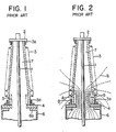
- Figure 1 shows a prior-art bushing which is the subject of Japanese Patent Specification, published under the number 58-5491 on January 31, 1983.
- numeral 1 designates a central conductor
- numeral 2 an upper terminal which is connected with the central conductor 1
- numeral 3 a porcelain tube which has the central conductor 1 inserted in the hollow part thereof.
- Symbol 3a denotes a fixture which is fastened to one end of the porcelain tube 3
- symbol 3b denotes a fixture which is fastened to the other end of the porcelain tube 3 and through which the upper terminal 2 and the other end of the porcelain tube 3 are hermetically fixed.
- Numeral 4 indicates a fitting flange on which the fixture 3a is mounted, and numeral 5 an electrode which is disposed in the bore part or annular hole of the fitting flange 4 and which moderates the concentration of an electric field at the upper end part of the fixture 3a.
- the electrode 5 is constructed in the shape of a cylinder encircling the central conductor 1 at a predetermined spacing therefrom, and it has a predetermined length from the one end toward the other end of the porcelain tube 3.
- a vessel 6 has a base portion 6a at the communicating hole part thereof, and the fitting flange 4 is mounted on the base portion 6a.
- the one end of the porcelain tube 3 is hermetically fixed to the vessel 6 for receiving electric equipment therein, and one end of the electrode 5 is connected with the vessel 6.
- the interior of the porcelain tube 3 as well as the vessel 6 is filled with an insulating gas 7 under a predetermined pressure.
- the flange 4 is earthed in any suitable way.
- the upper end part A of the electrode 5 is surrounded with the insulating gas 7 of high pressure exhibiting a high dielectric strength, and an electric field strength at which corona is generated is high therein.
- the upper end part B of the fixture 3a is surrounded with the atmospheric air, and hence, the electric field strength causing corona is low therein.
- the electrical design of a bushing conforms with a procedure wherein, with reference to the highest voltage to be applied between the central conductor 1 and the fitting flange 4, the height of the electrode 5 is determined so that the electric field strength of the part B may become less than the breakdown voltage of the atmospheric air, while the electric field strength of the upper end part A of the electrode 5 is set to be less than the breakdown voltage of the ambient insulating medium. Accordingly, the flashover voltage of the assembled bushing is determined by the magnitude of the electric field strength of the upper end part B of the fixture 3a. As the upper end of the electrode 5 becomes higher than that of the fixture 3a, the electric field strength of the part B lowers more, and the flashover voltage of the exterior rises more.
- the electric field strength of the upper end part A of the electrode 5 rises more as this part becomes remoter from the upper end part B of the fixture 3a. It is considered that, when the parts A and B are made extremely distant, there will be the limit at which the corona generating voltage of the part A becomes lower than that of the part B and beyond which the flashover takes place between the upper end of the electrode 5 and the central conductor 1 inside the bushing.
- the bushing is so designed as to keep the height of the electrode 5 small in order that the breakdown may occur from the upper end part B of the fixture 3a earlier.
- the measure of increasing the full length of the porcelain tube is required. This has lead to the disadvantages that the height of the bushing becomes greater than in the case of a condenser bushing, and that the cost of manufacture increases.
- a porcelain insulator surrounds a pressure tight sleeve which contains a conductor.
- Cylindrically shaped electrodes surround the conductor which act as capacitors to control the voltage.
- the electrodes are concentric and can be made of metallic material or a non-metallic conductor material.
- the metallic electrodes may be bare or coated with an insulating layer.
- United States Patent Specification 2,651,670 describes a porcelain pothead which includes an insulated cable.
- the cable is surrounded by cylindrically shaped sleeves which include a conductive portion covered with an insulating material.
- the cylinders are positioned telescopically with respect to one another and are concentric.
- German Patent Specification No. 948988 illustrates a paper insulator which is applied to a cylindrically shaped electrode in a high voltage apparatus.
- This invention has for its object to moderate the concentration of an electric field in a bushing.
- a bushing comprising:
- FIG. 3 shows an embodiment of this invention, in which numerals 1 to 4, 6 and 7 indicate the same parts as in the prior-art of Figures 1 and 2 and shall not be repeatedly explained.
- Numeral 9 indicates an electrode, which is in the shape of a cylinder having a predetermined diameter encircling the central conductor 1 at a predetermined distance therefrom, which has a predetermined length in its axial direction and one end of which is connected with the fitting flange 4.
- Shown at symbol 9a is an insulating member which covers the surfaces of the electrode 9.
- the insulating member 9a is a tape of plastic film which exhibits a high withstand voltage performance, and the tape is wound on the electrode 9 to a predetermined insulation thickness.
- the dielectric constant of the insulating layer 9a which is made of the plastic film and which is disposed on the surfaces of the electrode 9 is approximately 3 to 3.3 in contrast to 1 (one) of the insulating gas 7. Since the electric field on the surface of the electrode decreases in inverse proportion to the dielectric constant, the field strength of the surface of the electrode 9 lowers to about 1/3. In addition, the surface of the insulating layer 9a has a increased curvature, so that the field strength becomes still lower. Thus, the limit of the field strength on the surface of the upper end of the electrode 9 can be raised up to the dielectric strength of the insulating layer 9a.
- FIG 4 shows another embodiment.
- an electrode 10 whose surfaces are provided with an insulating layer 10a.
- the electrode 10 has a predetermined outside diameter which is smaller than the outside diameter of the electrode 9 and which is reduced at a part of predetermined length at one end with respect to the other end.
- the potential of the electrode 10 becomes a magnitude obtained by dividing a voltage by the capacitance C 1 between the central conductor 1 and the electrode 10 and the capacitance C 2 between the electrode 9 and the electrode 10.
- E denote the voltage applied across the electrode 9 and the conductor 1
- the potential e 1 of the electrode 10 relative to the grounded electrode 9 becomes as follows:
- the concentration of the electric field is shared by the respective electrodes 9 and 10.
- the electrode 10 is constructed of a plurality of parts which are successively joined by inserting one end of a part into the other end of another part and where such electrode 10 is inserted into the other end of the electrode 9, the number of places to share the concentration of the electric field increases in proportion to the number of the electrode parts, so that the potential to be shared by one place lowers, and the upper end position of the combined electrode can be made still higher.
- the electric field strength of the upper end of the fixture 3a becomes still lower, and the electric field distribution on the surface of the porcelain tube 3 becomes more uniform.
- FIG. 6 shows still another embodiment.
- An electrode 11 which is connected with the vessel 6 through the fitting flange 4 is constructed in the shape of a cylinder one end of which has a predetermined diameter and the other end of which is flared so as to become larger than the one end by a predetermined value.
- the electrode 11 is provided with an insulating layer 11a a which covers the surface of the electrode 11 by the use of a predetermined insulating member.
- Inserted in the other end of this electrode 11 is an electrode 12 which has a diameter smaller than that of the electrode 11 and whose surfaces are formed with an insulating layer 12a made of an insulating member.
- Further inserted in the electrode 12 is an electrode 13 which has a diameter smaller than that of the electrode 12 and whose surfaces are covered with an insulating layer 13a.
- a potential e l3 to act on the electrode 13 becomes:
- each of the electrodes 11, 12 and 13 is so formed as to flare at the other end relative to the one end as shown in the figure, the upper end of each electrode lies farther from the central conductor 1, and the degree of concentration of the electric field becomes lower than in the case of the electrodes in the shape of the straight cylinder both the ends of which have an identical diameter, so that the dielectric strength is more enhanced.
- the electrode structure flared from the one end toward the other end brings forth the advantage that, even when the number of electrodes is increased, electrodes having the same shape can be readily stacked by selecting the dimensions thereof.
- the insulating member to form the insulating layer of the electrode has been explained as being a plastic film.
- the same effect as in the embodiments can be expected even when the electrode is covered with an epoxy resin by injection molding or when insulating paper is wound on the electrode and impregnated with an epoxy resin which is then hardened.
- the fluid to fill the interior of the porcelain tube is not restricted to the insulating gas mentioned before, but it may well be an insulating oil or air.
Description
- This invention relates to a bushing in which the concentration of an electric field is moderated.
- Figure 1 shows a prior-art bushing which is the subject of Japanese Patent Specification, published under the number 58-5491 on January 31, 1983. Referring to the figure, numeral 1 designates a central conductor,
numeral 2 an upper terminal which is connected with the central conductor 1, andnumeral 3 a porcelain tube which has the central conductor 1 inserted in the hollow part thereof.Symbol 3a denotes a fixture which is fastened to one end of theporcelain tube 3, whilesymbol 3b denotes a fixture which is fastened to the other end of theporcelain tube 3 and through which theupper terminal 2 and the other end of theporcelain tube 3 are hermetically fixed.Numeral 4 indicates a fitting flange on which thefixture 3a is mounted, andnumeral 5 an electrode which is disposed in the bore part or annular hole of thefitting flange 4 and which moderates the concentration of an electric field at the upper end part of thefixture 3a. Theelectrode 5 is constructed in the shape of a cylinder encircling the central conductor 1 at a predetermined spacing therefrom, and it has a predetermined length from the one end toward the other end of theporcelain tube 3. Avessel 6 has abase portion 6a at the communicating hole part thereof, and thefitting flange 4 is mounted on thebase portion 6a. Upon attaching theflange 4, the one end of theporcelain tube 3 is hermetically fixed to thevessel 6 for receiving electric equipment therein, and one end of theelectrode 5 is connected with thevessel 6. The interior of theporcelain tube 3 as well as thevessel 6 is filled with aninsulating gas 7 under a predetermined pressure. Theflange 4 is earthed in any suitable way. - In the bushing of such construction, when a voltage is applied to the central conductor 1, equipotential surfaces 8 are distributed as indicated by broken lines in Figure 2, and the concentration of an electric field develops at the upper end part A of the
electrode 5. - Here, the upper end part A of the
electrode 5 is surrounded with theinsulating gas 7 of high pressure exhibiting a high dielectric strength, and an electric field strength at which corona is generated is high therein. In contrast, the upper end part B of thefixture 3a is surrounded with the atmospheric air, and hence, the electric field strength causing corona is low therein. When the height of theelectrode 5 is reduced, the distribution of the equipotential surfaces changes to lower the electric field strength at the part A and to raise that at the part B. - In general, the electrical design of a bushing conforms with a procedure wherein, with reference to the highest voltage to be applied between the central conductor 1 and the
fitting flange 4, the height of theelectrode 5 is determined so that the electric field strength of the part B may become less than the breakdown voltage of the atmospheric air, while the electric field strength of the upper end part A of theelectrode 5 is set to be less than the breakdown voltage of the ambient insulating medium. Accordingly, the flashover voltage of the assembled bushing is determined by the magnitude of the electric field strength of the upper end part B of thefixture 3a. As the upper end of theelectrode 5 becomes higher than that of thefixture 3a, the electric field strength of the part B lowers more, and the flashover voltage of the exterior rises more. However, the electric field strength of the upper end part A of theelectrode 5 rises more as this part becomes remoter from the upper end part B of thefixture 3a. It is considered that, when the parts A and B are made extremely distant, there will be the limit at which the corona generating voltage of the part A becomes lower than that of the part B and beyond which the flashover takes place between the upper end of theelectrode 5 and the central conductor 1 inside the bushing. - For such reason, the bushing is so designed as to keep the height of the
electrode 5 small in order that the breakdown may occur from the upper end part B of thefixture 3a earlier. To the end of enhancing the withstand voltage performance of the whole bushing, the measure of increasing the full length of the porcelain tube is required. This has lead to the disadvantages that the height of the bushing becomes greater than in the case of a condenser bushing, and that the cost of manufacture increases. - In French Patent Specification No. 2,316,709 a porcelain insulator surrounds a pressure tight sleeve which contains a conductor. Cylindrically shaped electrodes surround the conductor which act as capacitors to control the voltage. The electrodes are concentric and can be made of metallic material or a non-metallic conductor material. The metallic electrodes may be bare or coated with an insulating layer.
- United States Patent Specification 2,651,670 describes a porcelain pothead which includes an insulated cable. The cable is surrounded by cylindrically shaped sleeves which include a conductive portion covered with an insulating material. The cylinders are positioned telescopically with respect to one another and are concentric.
- German Patent Specification No. 948988 illustrates a paper insulator which is applied to a cylindrically shaped electrode in a high voltage apparatus.
- This invention has for its object to moderate the concentration of an electric field in a bushing.
- According to the present invention, there is provided a bushing comprising:
- a porcelain tube of insulating material, which is placed and fixed on a vessel for containing electric equipment, which vessel is filled with an insulating fluid, and the porcelain tube is open at its inner end to communicate with the interior of the vessel;
- an upper terminal which is fixed to an upper end part of said porcelain tube by an upper fixture, and which hermetically closes an upper end opening of said porcelain tube;
- a central conductor, which passes through a central part of said porcelain tube, and is electrically connected to said upper terminal;
- an electrically earthed fitting flange, and a lower fixture which are coupled to a base portion provided at a communicating hole part of said vessel, and which closes a peripheral edge of a lower end part of said porcelain tube hermetically against the ambient atmosphere;
- at least one substantially cylindrical, electric field-adjusting electrode arranged inside said porcelain tube with a pre-determined spacing from said central conductor, and electrically connected to said fitting flange;
- an insulating member formed so as to cover the inner and outer peripheral surfaces of said electrode and cylinder end parts thereof; characterised in that
- the or each electric field-adjusting electrode is flared from its lower end towards its upper end.
-
- Figure 1 is a front view of a prior-art bushing;
- Figure 2 is a diagram of an electric field distribution in the bushing of Figure 1;
- Figures 3 and 4 are front views each showing an embodiment of this invention;
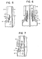
- Figure 5 is a diagram for explaining the operation of the bushing shown in Figure 4;
- Figure 6 is a front view of another embodiment; and
- Figure 7 is a diagram for explaining the operation of the bushing shown in Figure 6.
- In the drawings, the same symbols indicate the same or corresponding parts.
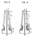
- The invention will now be described with reference to the drawings. Figure 3 shows an embodiment of this invention, in which numerals 1 to 4, 6 and 7 indicate the same parts as in the prior-art of Figures 1 and 2 and shall not be repeatedly explained.
Numeral 9 indicates an electrode, which is in the shape of a cylinder having a predetermined diameter encircling the central conductor 1 at a predetermined distance therefrom, which has a predetermined length in its axial direction and one end of which is connected with thefitting flange 4. Shown atsymbol 9a is an insulating member which covers the surfaces of theelectrode 9. Herein, theinsulating member 9a is a tape of plastic film which exhibits a high withstand voltage performance, and the tape is wound on theelectrode 9 to a predetermined insulation thickness. - In the bushing of Figure 3 thus constructed, the dielectric constant of the
insulating layer 9a which is made of the plastic film and which is disposed on the surfaces of theelectrode 9 is approximately 3 to 3.3 in contrast to 1 (one) of theinsulating gas 7. Since the electric field on the surface of the electrode decreases in inverse proportion to the dielectric constant, the field strength of the surface of theelectrode 9 lowers to about 1/3. In addition, the surface of theinsulating layer 9a has a increased curvature, so that the field strength becomes still lower. Thus, the limit of the field strength on the surface of the upper end of theelectrode 9 can be raised up to the dielectric strength of theinsulating layer 9a. - Figure 4 shows another embodiment. In the upper end part of the
electrode 9, there is inserted anelectrode 10 whose surfaces are provided with an insulating layer 10a. Theelectrode 10 has a predetermined outside diameter which is smaller than the outside diameter of theelectrode 9 and which is reduced at a part of predetermined length at one end with respect to the other end. As illustrated in Figure 5, the potential of theelectrode 10 becomes a magnitude obtained by dividing a voltage by the capacitance C1 between the central conductor 1 and theelectrode 10 and the capacitance C2 between theelectrode 9 and theelectrode 10. As the relationship, letting E denote the voltage applied across theelectrode 9 and the conductor 1, the potential e1 of theelectrode 10 relative to thegrounded electrode 9 becomes as follows:
respective electrodes - Accordingly, in a case where the
electrode 10 is constructed of a plurality of parts which are successively joined by inserting one end of a part into the other end of another part and wheresuch electrode 10 is inserted into the other end of theelectrode 9, the number of places to share the concentration of the electric field increases in proportion to the number of the electrode parts, so that the potential to be shared by one place lowers, and the upper end position of the combined electrode can be made still higher. Thus, the electric field strength of the upper end of thefixture 3a becomes still lower, and the electric field distribution on the surface of theporcelain tube 3 becomes more uniform. - Figure 6 shows still another embodiment. An electrode 11 which is connected with the
vessel 6 through thefitting flange 4 is constructed in the shape of a cylinder one end of which has a predetermined diameter and the other end of which is flared so as to become larger than the one end by a predetermined value. The electrode 11 is provided with an insulating layer 11a a which covers the surface of the electrode 11 by the use of a predetermined insulating member. Inserted in the other end of this electrode 11 is anelectrode 12 which has a diameter smaller than that of the electrode 11 and whose surfaces are formed with an insulating layer 12a made of an insulating member. Further inserted in theelectrode 12 is anelectrode 13 which has a diameter smaller than that of theelectrode 12 and whose surfaces are covered with an insulatinglayer 13a. Thus, as illustrated in Figure 7, when a voltage applied to the whole bushing is denoted by E(V), a potential e12 to act on theelectrode 12 becomes: -

electrode 13 becomes:
- When each of the
electrodes - In each of the foregoing embodiments, the insulating member to form the insulating layer of the electrode has been explained as being a plastic film. However, the same effect as in the embodiments can be expected even when the electrode is covered with an epoxy resin by injection molding or when insulating paper is wound on the electrode and impregnated with an epoxy resin which is then hardened. Further, the fluid to fill the interior of the porcelain tube is not restricted to the insulating gas mentioned before, but it may well be an insulating oil or air.
Claims (3)
Applications Claiming Priority (2)
| Application Number | Priority Date | Filing Date | Title |
|---|---|---|---|
| JP203101/82 | 1982-11-17 | ||
| JP57203101A JPS5991614A (en) | 1982-11-17 | 1982-11-17 | Bushing |
Publications (3)
| Publication Number | Publication Date |
|---|---|
| EP0109836A2 EP0109836A2 (en) | 1984-05-30 |
| EP0109836A3 EP0109836A3 (en) | 1987-10-14 |
| EP0109836B1 true EP0109836B1 (en) | 1990-03-21 |
Family
ID=16468398
Family Applications (1)
| Application Number | Title | Priority Date | Filing Date |
|---|---|---|---|
| EP83307037A Expired - Lifetime EP0109836B1 (en) | 1982-11-17 | 1983-11-17 | Bushing |
Country Status (5)
| Country | Link |
|---|---|
| US (1) | US4528421A (en) |
| EP (1) | EP0109836B1 (en) |
| JP (1) | JPS5991614A (en) |
| KR (1) | KR880001309B1 (en) |
| DE (1) | DE3381372D1 (en) |
Families Citing this family (6)
| Publication number | Priority date | Publication date | Assignee | Title |
|---|---|---|---|---|
| WO1999001874A1 (en) * | 1997-07-02 | 1999-01-14 | The Regents Of The University Of California | A method for improving performance of highly stressed electrical insulating structures |
| US20060157269A1 (en) * | 2005-01-18 | 2006-07-20 | Kopp Alvin B | Methods and apparatus for electric bushing fabrication |
| RU2380777C1 (en) * | 2005-12-30 | 2010-01-27 | Абб Текнолоджи Лтд. | High-voltage bushing and high-voltage device that comprises such bushing |
| CN101136269B (en) * | 2006-08-31 | 2013-03-27 | Abb研究有限公司 | High voltage bushing |
| SE531321C2 (en) * | 2007-07-05 | 2009-02-24 | Abb Technology Ag | High Voltage Cable Connection |
| EP2528071B1 (en) * | 2011-05-27 | 2018-08-08 | ABB Schweiz AG | High voltage arrangement comprising an insulating structure |
Citations (13)
| Publication number | Priority date | Publication date | Assignee | Title |
|---|---|---|---|---|
| US2651670A (en) | 1951-04-13 | 1953-09-08 | Gen Electric | High-voltage pothead with stress distributing means |
| DE1036967B (en) | 1954-03-30 | 1958-08-21 | Hartmann & Braun Ag | High voltage bushing |
| DE1051353B (en) | 1956-02-16 | 1959-02-26 | Siemens Ag | End closure made of cast resin for electrical cables |
| DE1107316B (en) | 1960-03-15 | 1961-05-25 | Kabelwerk Rheydt Akt Ges | Device for distributing the electrical stress along the insulation of cable fittings |
| DE1213026B (en) | 1961-12-08 | 1966-03-24 | Felten & Guilleaume Carlswerk | Radiation funnel wound from wire in turns concentric to the line axis for the termination of an insulated electrical high-voltage conductor |
| DE1465393A1 (en) | 1964-11-12 | 1969-03-06 | Calor Emag Elek Zitaets Ag | Cable entry to a grounded, tubular, gas-filled housing in which a high-voltage conductor is arranged |
| DE1949503A1 (en) | 1969-10-01 | 1971-04-08 | Kabel Metallwerke Ghh | Earth free cable termination for plastic - insulated hv cables |
| DE2016014A1 (en) | 1970-03-26 | 1971-10-07 | Siemens Ag | End termination for rubber or plastic-coated power cables or lines |
| DE2221204A1 (en) | 1972-04-29 | 1973-11-15 | Felten & Guilleaume Kabelwerk | END CLOSURE FOR PLASTIC INSULATED CABLES, IN PARTICULAR POLYAETHYLENE HIGH VOLTAGE CABLES |
| DE2226014A1 (en) | 1972-05-29 | 1973-12-06 | Felten & Guilleaume Kabelwerk | HERMETICALLY SEALED CABLE END CLOSURE FOR PLASTIC CABLES FOR INDOOR AND OUTDOOR AIR |
| DE2627653A1 (en) | 1975-07-03 | 1977-01-20 | Haefely & Cie Ag Emil | OUTDOOR HIGH VOLTAGE FEEDTHROUGH FOR SF TIEF 6 COMPRESSED GAS ISOLATED ELECTRICAL SYSTEMS |
| DE2944121A1 (en) | 1979-10-30 | 1981-05-14 | Siemens AG, 1000 Berlin und 8000 München | CONTROL ELEMENT FOR HIGH VOLTAGE DEVICES AND METHOD FOR PRODUCING A CONTROL ELEMENT |
| JPS585491A (en) | 1981-07-02 | 1983-01-12 | Janome Seimitsu Kogyo Kk | Manufacture of change-over valve of fluid rotary machine |
Family Cites Families (7)
| Publication number | Priority date | Publication date | Assignee | Title |
|---|---|---|---|---|
| DE948988C (en) * | 1941-04-17 | 1956-09-13 | Siemens Ag | Cylinder electrode for high voltage bushings |
| CH248940A (en) * | 1946-05-16 | 1947-05-31 | Bbc Brown Boveri & Cie | Termination for high voltage cables with metal sheath. |
| JPS52104798A (en) * | 1975-10-21 | 1977-09-02 | Ngk Insulators Ltd | Gas bushing |
| JPS5420398A (en) * | 1977-07-15 | 1979-02-15 | Toshiba Corp | Bushing |
| US4159401A (en) * | 1977-11-01 | 1979-06-26 | Tokyo Shibaura Kenki K.K. | Gas filled bushings with potential shields |
| JPS5485393A (en) * | 1977-12-20 | 1979-07-06 | Hitachi Ltd | Gas bushing |
| JPS55144615A (en) * | 1979-04-27 | 1980-11-11 | Mitsubishi Electric Corp | Gas bushing |
-
1982
- 1982-11-17 JP JP57203101A patent/JPS5991614A/en active Pending
-
1983
- 1983-10-15 KR KR1019830004884A patent/KR880001309B1/en not_active IP Right Cessation
- 1983-11-10 US US06/550,621 patent/US4528421A/en not_active Expired - Fee Related
- 1983-11-17 EP EP83307037A patent/EP0109836B1/en not_active Expired - Lifetime
- 1983-11-17 DE DE8383307037T patent/DE3381372D1/en not_active Revoked
Patent Citations (14)
| Publication number | Priority date | Publication date | Assignee | Title |
|---|---|---|---|---|
| US2651670A (en) | 1951-04-13 | 1953-09-08 | Gen Electric | High-voltage pothead with stress distributing means |
| DE1036967B (en) | 1954-03-30 | 1958-08-21 | Hartmann & Braun Ag | High voltage bushing |
| DE1051353B (en) | 1956-02-16 | 1959-02-26 | Siemens Ag | End closure made of cast resin for electrical cables |
| DE1107316B (en) | 1960-03-15 | 1961-05-25 | Kabelwerk Rheydt Akt Ges | Device for distributing the electrical stress along the insulation of cable fittings |
| DE1213026B (en) | 1961-12-08 | 1966-03-24 | Felten & Guilleaume Carlswerk | Radiation funnel wound from wire in turns concentric to the line axis for the termination of an insulated electrical high-voltage conductor |
| DE1465393A1 (en) | 1964-11-12 | 1969-03-06 | Calor Emag Elek Zitaets Ag | Cable entry to a grounded, tubular, gas-filled housing in which a high-voltage conductor is arranged |
| DE1949503A1 (en) | 1969-10-01 | 1971-04-08 | Kabel Metallwerke Ghh | Earth free cable termination for plastic - insulated hv cables |
| DE2016014A1 (en) | 1970-03-26 | 1971-10-07 | Siemens Ag | End termination for rubber or plastic-coated power cables or lines |
| DE2221204A1 (en) | 1972-04-29 | 1973-11-15 | Felten & Guilleaume Kabelwerk | END CLOSURE FOR PLASTIC INSULATED CABLES, IN PARTICULAR POLYAETHYLENE HIGH VOLTAGE CABLES |
| DE2226014A1 (en) | 1972-05-29 | 1973-12-06 | Felten & Guilleaume Kabelwerk | HERMETICALLY SEALED CABLE END CLOSURE FOR PLASTIC CABLES FOR INDOOR AND OUTDOOR AIR |
| DE2627653A1 (en) | 1975-07-03 | 1977-01-20 | Haefely & Cie Ag Emil | OUTDOOR HIGH VOLTAGE FEEDTHROUGH FOR SF TIEF 6 COMPRESSED GAS ISOLATED ELECTRICAL SYSTEMS |
| FR2316709A1 (en) | 1975-07-03 | 1977-01-28 | Haefely & Cie Ag Emil | HIGH TENSION CROSS-THROUGH INSULATOR, AVAILABLE WITH FREE AIR, FOR ELECTRICAL SYSTEMS INSULATED WITH COMPRESSED SULFUR HEXAFLUORIDE |
| DE2944121A1 (en) | 1979-10-30 | 1981-05-14 | Siemens AG, 1000 Berlin und 8000 München | CONTROL ELEMENT FOR HIGH VOLTAGE DEVICES AND METHOD FOR PRODUCING A CONTROL ELEMENT |
| JPS585491A (en) | 1981-07-02 | 1983-01-12 | Janome Seimitsu Kogyo Kk | Manufacture of change-over valve of fluid rotary machine |
Also Published As
| Publication number | Publication date |
|---|---|
| KR840006546A (en) | 1984-11-30 |
| EP0109836A3 (en) | 1987-10-14 |
| EP0109836A2 (en) | 1984-05-30 |
| KR880001309B1 (en) | 1988-07-22 |
| DE3381372D1 (en) | 1990-04-26 |
| US4528421A (en) | 1985-07-09 |
| JPS5991614A (en) | 1984-05-26 |
Similar Documents
| Publication | Publication Date | Title |
|---|---|---|
| US8455763B2 (en) | Plug-in bushing and high-voltage installation having a bushing such as this | |
| US11605501B2 (en) | HV apparatus and a method of manufacturing such apparatus | |
| US20200174042A1 (en) | High-voltage impedance assembly | |
| EP0053363B1 (en) | Bushing for gas-insulated electrical equipment | |
| EP0109836B1 (en) | Bushing | |
| EP0688075B1 (en) | An elastomeric capacitively graded high voltage cable termination | |
| US3055968A (en) | Condenser bushing | |
| US4227035A (en) | Modular condenser bushing | |
| JP2693188B2 (en) | High voltage voltage converter | |
| WO2008027007A1 (en) | High voltage dc bushing and device comprising such high voltage bushing | |
| US2651670A (en) | High-voltage pothead with stress distributing means | |
| EP1103988B1 (en) | SEmi-capacitance graded bushing insulator of the type with insulating gas filling, such as SF6 | |
| US1563946A (en) | High-tension terminal | |
| US2894054A (en) | Voltage grading in high-voltage switchgear insulation | |
| SE543113C2 (en) | Elastic tubular high-voltage insulating body | |
| US4497975A (en) | Resistor and capacitor graded termination | |
| US3335215A (en) | Stress relief apparatus | |
| US2859271A (en) | High voltage bushing | |
| US3033915A (en) | Potheads and cable terminals | |
| US3523157A (en) | Cast insulating bushing with axially disposed electrical cable | |
| EP0085966B1 (en) | Bushing for gas-insulated electrical equipment | |
| US3378627A (en) | Adaptors for terminating devices in high voltage power cables | |
| US20220172890A1 (en) | Capacitor assembly, method for production thereof and converter assembly containing the capacitor assembly | |
| US11862405B2 (en) | High-voltage feed-through capacitor | |
| US20230260715A1 (en) | High-voltage feed-through capacitor |
Legal Events
| Date | Code | Title | Description |
|---|---|---|---|
| PUAI | Public reference made under article 153(3) epc to a published international application that has entered the european phase |
Free format text: ORIGINAL CODE: 0009012 |
|
| AK | Designated contracting states |
Designated state(s): CH DE GB LI SE |
|
| PUAL | Search report despatched |
Free format text: ORIGINAL CODE: 0009013 |
|
| AK | Designated contracting states |
Kind code of ref document: A3 Designated state(s): CH DE GB LI SE |
|
| 17P | Request for examination filed |
Effective date: 19880118 |
|
| 17Q | First examination report despatched |
Effective date: 19880718 |
|
| GRAA | (expected) grant |
Free format text: ORIGINAL CODE: 0009210 |
|
| AK | Designated contracting states |
Kind code of ref document: B1 Designated state(s): CH DE GB LI SE |
|
| REF | Corresponds to: |
Ref document number: 3381372 Country of ref document: DE Date of ref document: 19900426 |
|
| REG | Reference to a national code |
Ref country code: GB Ref legal event code: 727 |
|
| REG | Reference to a national code |
Ref country code: GB Ref legal event code: 727A |
|
| PGFP | Annual fee paid to national office [announced via postgrant information from national office to epo] |
Ref country code: GB Payment date: 19901107 Year of fee payment: 8 |
|
| PGFP | Annual fee paid to national office [announced via postgrant information from national office to epo] |
Ref country code: SE Payment date: 19901114 Year of fee payment: 8 |
|
| PGFP | Annual fee paid to national office [announced via postgrant information from national office to epo] |
Ref country code: CH Payment date: 19901203 Year of fee payment: 8 |
|
| REG | Reference to a national code |
Ref country code: GB Ref legal event code: 727B |
|
| PGFP | Annual fee paid to national office [announced via postgrant information from national office to epo] |
Ref country code: DE Payment date: 19901228 Year of fee payment: 8 |
|
| PLBI | Opposition filed |
Free format text: ORIGINAL CODE: 0009260 |
|
| PLBI | Opposition filed |
Free format text: ORIGINAL CODE: 0009260 |
|
| REG | Reference to a national code |
Ref country code: GB Ref legal event code: SP |
|
| 26 | Opposition filed |
Opponent name: MWB MESSWANDLER-BAU AG Effective date: 19901220 |
|
| 26 | Opposition filed |
Opponent name: SIEMENS AG GRPA3 ERL S Effective date: 19901218 Opponent name: MWB MESSWANDLER-BAU AG Effective date: 19901220 |
|
| PG25 | Lapsed in a contracting state [announced via postgrant information from national office to epo] |
Ref country code: GB Effective date: 19911117 |
|
| PG25 | Lapsed in a contracting state [announced via postgrant information from national office to epo] |
Ref country code: SE Effective date: 19911118 |
|
| RDAG | Patent revoked |
Free format text: ORIGINAL CODE: 0009271 |
|
| STAA | Information on the status of an ep patent application or granted ep patent |
Free format text: STATUS: PATENT REVOKED |
|
| GBPC | Gb: european patent ceased through non-payment of renewal fee | ||
| REG | Reference to a national code |
Ref country code: CH Ref legal event code: PL |
|
| 27W | Patent revoked |
Effective date: 19920402 |
|
| EUG | Se: european patent has lapsed |
Ref document number: 83307037.8 Effective date: 19920604 |
|
| PLAB | Opposition data, opponent's data or that of the opponent's representative modified |
Free format text: ORIGINAL CODE: 0009299OPPO |