EP0109768A2 - Rotierender Hochtemperaturreaktor - Google Patents
Rotierender Hochtemperaturreaktor Download PDFInfo
- Publication number
- EP0109768A2 EP0109768A2 EP83306413A EP83306413A EP0109768A2 EP 0109768 A2 EP0109768 A2 EP 0109768A2 EP 83306413 A EP83306413 A EP 83306413A EP 83306413 A EP83306413 A EP 83306413A EP 0109768 A2 EP0109768 A2 EP 0109768A2
- Authority
- EP
- European Patent Office
- Prior art keywords
- drum
- reactor
- vanes
- solid material
- gas
- Prior art date
- Legal status (The legal status is an assumption and is not a legal conclusion. Google has not performed a legal analysis and makes no representation as to the accuracy of the status listed.)
- Withdrawn
Links
Images
Classifications
-
- B—PERFORMING OPERATIONS; TRANSPORTING
- B01—PHYSICAL OR CHEMICAL PROCESSES OR APPARATUS IN GENERAL
- B01J—CHEMICAL OR PHYSICAL PROCESSES, e.g. CATALYSIS OR COLLOID CHEMISTRY; THEIR RELEVANT APPARATUS
- B01J8/00—Chemical or physical processes in general, conducted in the presence of fluids and solid particles; Apparatus for such processes
- B01J8/08—Chemical or physical processes in general, conducted in the presence of fluids and solid particles; Apparatus for such processes with moving particles
- B01J8/10—Chemical or physical processes in general, conducted in the presence of fluids and solid particles; Apparatus for such processes with moving particles moved by stirrers or by rotary drums or rotary receptacles or endless belts
-
- F—MECHANICAL ENGINEERING; LIGHTING; HEATING; WEAPONS; BLASTING
- F23—COMBUSTION APPARATUS; COMBUSTION PROCESSES
- F23G—CREMATION FURNACES; CONSUMING WASTE PRODUCTS BY COMBUSTION
- F23G5/00—Incineration of waste; Incinerator constructions; Details, accessories or control therefor
- F23G5/02—Incineration of waste; Incinerator constructions; Details, accessories or control therefor with pretreatment
- F23G5/027—Incineration of waste; Incinerator constructions; Details, accessories or control therefor with pretreatment pyrolising or gasifying stage
- F23G5/0276—Incineration of waste; Incinerator constructions; Details, accessories or control therefor with pretreatment pyrolising or gasifying stage using direct heating
-
- F—MECHANICAL ENGINEERING; LIGHTING; HEATING; WEAPONS; BLASTING
- F23—COMBUSTION APPARATUS; COMBUSTION PROCESSES
- F23G—CREMATION FURNACES; CONSUMING WASTE PRODUCTS BY COMBUSTION
- F23G5/00—Incineration of waste; Incinerator constructions; Details, accessories or control therefor
- F23G5/20—Incineration of waste; Incinerator constructions; Details, accessories or control therefor having rotating or oscillating drums
-
- F—MECHANICAL ENGINEERING; LIGHTING; HEATING; WEAPONS; BLASTING
- F27—FURNACES; KILNS; OVENS; RETORTS
- F27B—FURNACES, KILNS, OVENS OR RETORTS IN GENERAL; OPEN SINTERING OR LIKE APPARATUS
- F27B7/00—Rotary-drum furnaces, i.e. horizontal or slightly inclined
- F27B7/10—Rotary-drum furnaces, i.e. horizontal or slightly inclined internally heated, e.g. by means of passages in the wall
-
- F—MECHANICAL ENGINEERING; LIGHTING; HEATING; WEAPONS; BLASTING
- F27—FURNACES; KILNS; OVENS; RETORTS
- F27D—DETAILS OR ACCESSORIES OF FURNACES, KILNS, OVENS OR RETORTS, IN SO FAR AS THEY ARE OF KINDS OCCURRING IN MORE THAN ONE KIND OF FURNACE
- F27D17/00—Arrangements for using waste heat; Arrangements for using, or disposing of, waste gases
-
- B—PERFORMING OPERATIONS; TRANSPORTING
- B01—PHYSICAL OR CHEMICAL PROCESSES OR APPARATUS IN GENERAL
- B01J—CHEMICAL OR PHYSICAL PROCESSES, e.g. CATALYSIS OR COLLOID CHEMISTRY; THEIR RELEVANT APPARATUS
- B01J2219/00—Chemical, physical or physico-chemical processes in general; Their relevant apparatus
- B01J2219/18—Details relating to the spatial orientation of the reactor
- B01J2219/182—Details relating to the spatial orientation of the reactor horizontal
Definitions
- This invention relates to an improved reactor for heating solid material to a high temperature.
- An example of a process to which the reactor of the present invention may be applied is in the incineration of solid combustible waste.
- Such reactors are frequently required to operate at temperatures up - to 1000°C. Hitherto such high temperature process operations have been carried out in long rotary refractory lined kilns which'tend to be very large, to be expensive to construct, and to be thermally inefficient. More energy efficient machines are available for high temperature processes, for example fluidised bed reactors and shaft preheaters and coolers; however the size and type of material suitable for processing in such equipment is limited. Travelling grate preheaters and coolers that are energy efficient and do accept a wide variation in material size and type are very expensive to manufacture and mechanically complex.
- the present invention is directed at providing a ) mechanically simple rotary reactor which has a thermal efficiency which shows improvement of fifty percent or more over that of a refractory lined rotary kiln and which is capable of handling a very diverse range of material types and sizes.
- a rotary high temperature reactor comprising a rotary drum of heat resistant material mounted for rotation about a substantially horizontal axis, said drum comprising a peripheral shell and a plurality of vanes extending longitudinally of and within said shell to define passages closed at their radially outer side by the shell and open at their radially inner side; means for rotating the drum; means for feeding solid material to be treated into one end of the drum; means for collecting treated solid material from the other end of the drum, the drum being adapted, upon rotation, to feed solid material from the inlet to the outlet end thereof; and means for feeding gas for treatment of the solid material into the ends of the passages defined between the vanes, such gas feeding means being adapted to feed the gas only into those passages which at that particular time, during use of the reactor, are covered by solid material being tumbled in the drum, characterized in-that said gas feeding means is adapted to supply hot gas in an amount insufficient to complete the reaction in the drum such that combustible gases are given off from the outlet end of the
- the vanes each have a flange at their inner end extending in a substantially circumferential direction to resist the entry of solid material being treated in the drum into the passages between the vanes.
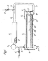
- the rotary reactor is shown as comprising a drum 2 mounted for rotation about a substantially horizontal axis.
- Diagrammatically illustrated at 33 is a supporting roller driven to rotate the drum slowly during use thereof.
- the reactor extends between an inlet chamber 3 and an outlet chamber 4, the outlet chamber being provided with a solids discharge means 5 and the inlet chamber being provided with a solids inlet chute 6.
- the conduit 7 provides a supply of hot gas to the reactor while a conduit 8 leads from the chamber 4 to a fan 9.
- a supply of fresh air is fed via a control valve 15 to the conduit 8.
- the mixture of hot exhaust gases from the reactor 2 and the fresh air is supplied via the fan 9 to a burner 10 in which the combustible gases are ignited by the flame 32 and burned in an excess of air to provide flue gases which are fed to a conduit 11 leading to a flue 12 via a control valve 13 and to the conduit 7 via a control valve 14.
- the butterfly vanes of the valves 13, 14 and 15 are controlled so as to provide an adequate supply of air to the burner 10 and also so to divide the flow of flue gas from the conduit 11 that hot gases are supplied to the conduit 7 containing about fifty percent of the air required for complete combustion of the solid materials in the reactor.
- Starved air combustion of this type ensures that the burning bed of material in the primary combustion chamber reaches a very high temperature, giving complete burn-out and, in the case of contaminated waste, a sterile and non-toxic ash.
- Starved air incineration can only truly be achieved by passing the combustion air through the bed of combustible material and hitherto this has only been possible in batch or intermittent operating machines.
- Prior rotary refractory lined incinerators where the combustion air passes over, not through, the bed of combustible material does not genuinely achieve this requirement.
- combustible waste is introduced at the feed end of the cylinder via the chute 6 and ash is continuously discharged into the chamber 4 from the discharge end of the rotary drum.
- Combustion air at fifty percent stoichiometric is passed through the tumbling bed of waste in the drum and the combustible and volatile gases given off are further burned to completion in the afterburner 10.
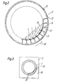
- vanes 26 defining passages 21 extending longitudinally of the drum for conducting the inlet gases so that they are discharged through the tumbling solid material in the drum.
- the drum 2 is shown as comprising an outer heat resisting steel casing 22 lined with refractory material 23 and provided around its internal surface with circumferentially spaced longitudinally extending vanes 26, the passages 21 being defined between successive vaneso
- a flange 27 extending in a circumferential direction towards, preferably to overlap, the edge of an immediately adjacent vane.
- Gas outlet slits are defined between the edges of the flange 27 and the vanes 26 overlapped thereby.
- the gas outlet slits between the vanes may either extend continuously for the full length of the reactor or may be in the form of shorter slits with connections between adjacent vanes being provided intermittently along the reactor for strengthening purposes.
- FIG. 3 illustrates how the plenum chamber 30 is defined by a barrier 31 to ensure that the gas to be passed through the solid material in the reactor is only supplied to the required ones of the heater passages having the outlets covered by the tumbling solid material in the drum.
- the reactor drum 2 will be rotated about a slightly downwardly inclined axis so as to cause continuous flow and movement of the solid material from the feed to the discharge end of the drum.
- feed arrangements could be used, for example, the vanes themselves may be so shaped as to provide a driving motion to cause material to move along the drum consequent upon rotation thereof, In order to allow the reactor to cope with different materials it is preferred that it rely upon inclination of the drum axis to cause the flow of solid material with the inclination and the speed of the drum being variable as required.
- the drum could be fabricated from a heat resisting steel or other metal, depending upon the drum size and operating temperature.
- the vanes themselves also may be either fabricated from heat resisting steels or other metals or be cast in a refractory material.
- the number of vanes provided around the drum circumference will depend upon the drum diameter and also upon the treatment required, but typically, the number of vanes may be 24 to 48.
- reactor drum has been illustrated as being cylindrical it will be appreciated that this is not essential and in some applications it may be of other shapes, in particular frusto-conical with the lowermost generator of the frustum being downwardly inclined from the inlet to the outlet end of the drum.
Landscapes
- Engineering & Computer Science (AREA)
- Mechanical Engineering (AREA)
- General Engineering & Computer Science (AREA)
- Chemical & Material Sciences (AREA)
- Environmental & Geological Engineering (AREA)
- Organic Chemistry (AREA)
- Chemical Kinetics & Catalysis (AREA)
- Muffle Furnaces And Rotary Kilns (AREA)
- Incineration Of Waste (AREA)
- Gasification And Melting Of Waste (AREA)
- Devices And Processes Conducted In The Presence Of Fluids And Solid Particles (AREA)
Applications Claiming Priority (2)
| Application Number | Priority Date | Filing Date | Title |
|---|---|---|---|
| GB8232627 | 1982-11-16 | ||
| GB08232627A GB2130696B (en) | 1982-11-16 | 1982-11-16 | Improved rotary high temperature reactor |
Publications (2)
| Publication Number | Publication Date |
|---|---|
| EP0109768A2 true EP0109768A2 (de) | 1984-05-30 |
| EP0109768A3 EP0109768A3 (de) | 1985-11-27 |
Family
ID=10534274
Family Applications (1)
| Application Number | Title | Priority Date | Filing Date |
|---|---|---|---|
| EP83306413A Withdrawn EP0109768A3 (de) | 1982-11-16 | 1983-10-21 | Rotierender Hochtemperaturreaktor |
Country Status (4)
| Country | Link |
|---|---|
| US (1) | US4541346A (de) |
| EP (1) | EP0109768A3 (de) |
| JP (1) | JPS59109238A (de) |
| GB (1) | GB2130696B (de) |
Cited By (1)
| Publication number | Priority date | Publication date | Assignee | Title |
|---|---|---|---|---|
| WO2015179770A1 (en) * | 2014-05-22 | 2015-11-26 | Novelis Inc. | High organic concurrent decoating kiln |
Families Citing this family (15)
| Publication number | Priority date | Publication date | Assignee | Title |
|---|---|---|---|---|
| US4794871A (en) * | 1985-08-19 | 1989-01-03 | Environment Protection Engineers, Inc. | Method and installation for the treatment of material contaminated with toxic organic compounds |
| US4745869A (en) * | 1987-06-22 | 1988-05-24 | Westinghouse Electric Corp. | Method and apparatus for calcining limestone using coal combustion for heating |
| DE3724541A1 (de) * | 1987-07-24 | 1989-02-02 | Applied Ind Materials | Verfahren und anlage zur herstellung von rohstoff-briketts fuer die erzeugung von silicium oder von siliciumcarbid oder von ferrosilicium |
| US5220874A (en) * | 1988-03-22 | 1993-06-22 | Keating Environmental Service, Inc. | Method and apparatus for stripping volatile organic compounds from solid materials |
| US4961391A (en) * | 1989-03-29 | 1990-10-09 | International Technology Corporation | Thermal treatment process for organically contaminated material |
| HUT69890A (en) * | 1992-07-14 | 1995-09-28 | Ash Grove Cement Co | Method for improved manufacture of cement in long kilns |
| DE4224571C2 (de) * | 1992-07-24 | 1994-06-16 | Babcock Anlagen Gmbh | Drehrohrofen |
| US5375535A (en) * | 1993-01-11 | 1994-12-27 | Ash Grove Cement Company | Method and apparatus for improved manufacture of cement in long kilns |
| US5392721A (en) * | 1994-05-06 | 1995-02-28 | Technology Development Corp. | Method for recycling papermaking sludge |
| US5788481A (en) * | 1995-11-15 | 1998-08-04 | Lockhead Haggerty Engineering & Manufacturing Co. Ltd. | Carbon reactivation apparatus |
| US5902040A (en) * | 1997-01-21 | 1999-05-11 | Gentec Equipment Company | Asphalt plant including flame arrester |
| DE10240249B3 (de) * | 2002-08-31 | 2004-02-26 | Enerco Bv | Anlage zum Trocknen und Aufbereiten von rieselfähigem mineralischem Gut |
| GB0506033D0 (en) * | 2005-03-24 | 2005-04-27 | Perry Ophneil H | Apparatus and method for thermally removing coatings and/or impurities |
| CN103090682B (zh) * | 2013-02-05 | 2015-05-27 | 广西藤县雅照钛白有限公司 | 煅烧及余热回收方法和设备 |
| DE102015005416B4 (de) * | 2015-04-29 | 2023-11-30 | Khd Humboldt Wedag Gmbh | Verfahren zum Betrieb eines Calcinators mit einem Gasbrenner |
Family Cites Families (26)
| Publication number | Priority date | Publication date | Assignee | Title |
|---|---|---|---|---|
| GB172302A (en) * | 1920-12-01 | 1923-04-30 | Felix Frank | Improvements in the treatment of carbonaceous and other materials |
| DE417688C (de) * | 1921-01-21 | 1925-08-14 | Eugen Weiss | Verfahren zum Verschwelen von festen Brennstoffen im Drehrohrofen |
| DE513123C (de) * | 1926-01-20 | 1930-11-24 | Adam Helmer Pehrson | Verfahren zur Beheizung der Beschickung eines Drehofens und Drehofen zur Ausfuehrung des Verfahrens |
| GB269892A (en) * | 1926-04-24 | 1928-05-03 | Gustav Bojner | Improvements in or relating to rotary furnaces |
| US2020960A (en) * | 1933-10-24 | 1935-11-12 | Pehrson Johan Marten | Treatment of materials in rotating furnaces or drums by hot gas |
| US2549787A (en) * | 1947-11-21 | 1951-04-24 | John B Dube | Calcining kiln |
| GB655014A (en) * | 1948-11-10 | 1951-07-04 | Link Belt Co | Improvements relating to rotary driers or coolers |
| GB905659A (en) * | 1957-10-24 | 1962-09-12 | Dunford & Elliott Process Engi | Improvements in a method and apparatus for the exchange of heat between gases and particulate materials |
| BE647610A (de) * | 1963-05-06 | |||
| US3862887A (en) * | 1971-12-22 | 1975-01-28 | Monsanto Enviro Chem Syst | Method for processing heat-decomposable non-gaseous materials |
| US3807321A (en) * | 1972-07-14 | 1974-04-30 | Air Preheater | Controlled temperature incinerator |
| JPS5221833B2 (de) * | 1973-07-12 | 1977-06-13 | ||
| US3822651A (en) * | 1973-09-04 | 1974-07-09 | D Harris | Water cooled kiln for waste disposal |
| US3938449A (en) * | 1974-03-18 | 1976-02-17 | Watson Industrial Properties | Waste disposal facility and process therefor |
| DE2512461A1 (de) * | 1975-03-21 | 1976-09-30 | Froeling Siegofa Abfalltech | Verfahren zur pyrolyse von abfallstoffen und rotationsretorte zur anwendung dieses verfahrens mit der moeglichkeit der nachfolgenden verbrennung und waermenutzung |
| US3995988A (en) * | 1975-05-23 | 1976-12-07 | Challenge-Cook Bros., Incorporated | Fuel saving apparatus and method for textile drying and finishing |
| US4037543A (en) * | 1976-02-27 | 1977-07-26 | Angelo James F | Pollution free combination carbonization apparatus and furnace |
| GB1585584A (en) * | 1976-06-08 | 1981-03-04 | Kobe Steel Ltd | Process and apparatus for heating solid materials containing volatile matter |
| AT387273B (de) * | 1976-10-29 | 1988-12-27 | Perlmooser Zementwerke Ag | Verfahren zur verwertung von abfallstoffen mit brennbaren bestandteilen |
| US4083752A (en) * | 1976-11-10 | 1978-04-11 | Monsanto Company | Rotary retort |
| US4091748A (en) * | 1976-12-03 | 1978-05-30 | Mansfield Carbon Products, Inc. | Method and apparatus for producing gas from solid municipal waste |
| US4191530A (en) * | 1978-09-21 | 1980-03-04 | Bearce Wendell E | Dryer |
| US4266931A (en) * | 1979-02-01 | 1981-05-12 | Holger Struckmann | Apparatus and method of heating particulate material |
| US4226584A (en) * | 1979-04-02 | 1980-10-07 | O'connor Engineering Laboratories, Inc. | Rotary combustor wall |
| US4376343A (en) * | 1981-07-21 | 1983-03-15 | White Henry J | Method and apparatus for drying bagasse |
| US4411204A (en) * | 1981-12-07 | 1983-10-25 | Combustion Engineering, Inc. | Method of firing a pulverized fuel-fired steam generator |
-
1982
- 1982-11-16 GB GB08232627A patent/GB2130696B/en not_active Expired
-
1983
- 1983-10-21 EP EP83306413A patent/EP0109768A3/de not_active Withdrawn
- 1983-11-14 JP JP58212629A patent/JPS59109238A/ja active Pending
- 1983-11-15 US US06/551,924 patent/US4541346A/en not_active Expired - Fee Related
Cited By (4)
| Publication number | Priority date | Publication date | Assignee | Title |
|---|---|---|---|---|
| WO2015179770A1 (en) * | 2014-05-22 | 2015-11-26 | Novelis Inc. | High organic concurrent decoating kiln |
| US10527280B2 (en) | 2014-05-22 | 2020-01-07 | Novelis Inc. | High organic concurrent decoating kiln |
| KR20200024365A (ko) * | 2014-05-22 | 2020-03-06 | 노벨리스 인크. | 고 유기 병행 탈코팅 가마 |
| KR102399586B1 (ko) | 2014-05-22 | 2022-05-18 | 노벨리스 인크. | 고 유기 병행 탈코팅 가마 |
Also Published As
| Publication number | Publication date |
|---|---|
| EP0109768A3 (de) | 1985-11-27 |
| US4541346A (en) | 1985-09-17 |
| GB2130696A (en) | 1984-06-06 |
| JPS59109238A (ja) | 1984-06-23 |
| GB2130696B (en) | 1986-04-16 |
Similar Documents
| Publication | Publication Date | Title |
|---|---|---|
| US4541346A (en) | Rotary high temperature reactor | |
| US4462793A (en) | Rotary kiln and method of using such a kiln | |
| US3774555A (en) | Compact incinerator | |
| US3905757A (en) | Apparatus and method for distributing material being processed over a furnace hearth floor | |
| RU2230988C2 (ru) | Способ и устройство для сжигания горючих отходов во время производства цементного клинкера | |
| EP0415539B1 (de) | Apparat zur Wärmebehandlung von kontaminiertem, stückigem Material | |
| US4200262A (en) | Method and apparatus for removing combustible material from metal scrap | |
| US4859177A (en) | Apparatus for incinerating combustible material | |
| US3380407A (en) | Rotary incinerators for waste and refuse matter | |
| US5927216A (en) | Burner apparatus | |
| US4424755A (en) | Incineration system having cyclonic oxidation chamber | |
| JPS6119307Y2 (de) | ||
| US6860735B1 (en) | Rotary kiln | |
| CA1091010A (en) | Rotary kiln plant | |
| JP2001090922A (ja) | ロータリキルン | |
| US3242888A (en) | Incineration apparatus | |
| US3827379A (en) | Rotary kiln type solid waste incinerating system and method | |
| US4377117A (en) | Particulate waste wood firing system | |
| JP2003103243A (ja) | 揮発性有機化合物を含む汚染土壌の処理方法、セメント製造方法および加熱処理装置 | |
| EP3106529B1 (de) | Verfahren und anlage zum verhütten von metallen | |
| US5906483A (en) | Rotary film calciner | |
| US4377115A (en) | Furnace for burning particulate wood waste material | |
| RU2292515C2 (ru) | Способ утилизации городских отходов и устройство, его обеспечивающее | |
| CA1300874C (en) | Apparatus and method for disposing of waste material | |
| RU2187759C2 (ru) | Печь для сжигания твердых отходов |
Legal Events
| Date | Code | Title | Description |
|---|---|---|---|
| PUAI | Public reference made under article 153(3) epc to a published international application that has entered the european phase |
Free format text: ORIGINAL CODE: 0009012 |
|
| AK | Designated contracting states |
Designated state(s): AT BE CH DE FR IT LI LU NL SE |
|
| PUAL | Search report despatched |
Free format text: ORIGINAL CODE: 0009013 |
|
| AK | Designated contracting states |
Designated state(s): AT BE CH DE FR IT LI LU NL SE |
|
| 17P | Request for examination filed |
Effective date: 19860130 |
|
| 17Q | First examination report despatched |
Effective date: 19861124 |
|
| STAA | Information on the status of an ep patent application or granted ep patent |
Free format text: STATUS: THE APPLICATION IS DEEMED TO BE WITHDRAWN |
|
| 18D | Application deemed to be withdrawn |
Effective date: 19870407 |
|
| RIN1 | Information on inventor provided before grant (corrected) |
Inventor name: CULLIFORD, MICHAEL DOUGLAS |