EP0109765B1 - Slab lifter - Google Patents
Slab lifter Download PDFInfo
- Publication number
- EP0109765B1 EP0109765B1 EP83306394A EP83306394A EP0109765B1 EP 0109765 B1 EP0109765 B1 EP 0109765B1 EP 83306394 A EP83306394 A EP 83306394A EP 83306394 A EP83306394 A EP 83306394A EP 0109765 B1 EP0109765 B1 EP 0109765B1
- Authority
- EP
- European Patent Office
- Prior art keywords
- slab
- gripping
- degrees
- lifting device
- bar
- Prior art date
- Legal status (The legal status is an assumption and is not a legal conclusion. Google has not performed a legal analysis and makes no representation as to the accuracy of the status listed.)
- Expired
Links
- 230000000087 stabilizing effect Effects 0.000 claims 1
- 239000003381 stabilizer Substances 0.000 description 10
- 239000007787 solid Substances 0.000 description 6
- 229910000831 Steel Inorganic materials 0.000 description 3
- 230000008878 coupling Effects 0.000 description 3
- 238000010168 coupling process Methods 0.000 description 3
- 238000005859 coupling reaction Methods 0.000 description 3
- 239000013536 elastomeric material Substances 0.000 description 3
- 239000010959 steel Substances 0.000 description 3
- 229910000746 Structural steel Inorganic materials 0.000 description 2
- 238000010276 construction Methods 0.000 description 2
- 238000010586 diagram Methods 0.000 description 2
- 239000004575 stone Substances 0.000 description 2
- XLYOFNOQVPJJNP-UHFFFAOYSA-N water Substances O XLYOFNOQVPJJNP-UHFFFAOYSA-N 0.000 description 2
- 241000272525 Anas platyrhynchos Species 0.000 description 1
- 229910000639 Spring steel Inorganic materials 0.000 description 1
- 238000005452 bending Methods 0.000 description 1
- 238000004140 cleaning Methods 0.000 description 1
- 229920001971 elastomer Polymers 0.000 description 1
- 239000000806 elastomer Substances 0.000 description 1
- 230000003993 interaction Effects 0.000 description 1
- 239000002184 metal Substances 0.000 description 1
- 229910052751 metal Inorganic materials 0.000 description 1
- 230000001737 promoting effect Effects 0.000 description 1
Images


Classifications
-
- B—PERFORMING OPERATIONS; TRANSPORTING
- B66—HOISTING; LIFTING; HAULING
- B66F—HOISTING, LIFTING, HAULING OR PUSHING, NOT OTHERWISE PROVIDED FOR, e.g. DEVICES WHICH APPLY A LIFTING OR PUSHING FORCE DIRECTLY TO THE SURFACE OF A LOAD
- B66F19/00—Hoisting, lifting, hauling or pushing, not otherwise provided for
- B66F19/005—Lifting devices for manhole covers
-
- B—PERFORMING OPERATIONS; TRANSPORTING
- B65—CONVEYING; PACKING; STORING; HANDLING THIN OR FILAMENTARY MATERIAL
- B65G—TRANSPORT OR STORAGE DEVICES, e.g. CONVEYORS FOR LOADING OR TIPPING, SHOP CONVEYOR SYSTEMS OR PNEUMATIC TUBE CONVEYORS
- B65G7/00—Devices for assisting manual moving or tilting heavy loads
- B65G7/12—Load carriers, e.g. hooks, slings, harness, gloves, modified for load carrying
-
- E—FIXED CONSTRUCTIONS
- E01—CONSTRUCTION OF ROADS, RAILWAYS, OR BRIDGES
- E01C—CONSTRUCTION OF, OR SURFACES FOR, ROADS, SPORTS GROUNDS, OR THE LIKE; MACHINES OR AUXILIARY TOOLS FOR CONSTRUCTION OR REPAIR
- E01C19/00—Machines, tools or auxiliary devices for preparing or distributing paving materials, for working the placed materials, or for forming, consolidating, or finishing the paving
- E01C19/52—Apparatus for laying individual preformed surfacing elements, e.g. kerbstones
- E01C19/526—Apparatus for laying individual preformed surfacing elements, e.g. kerbstones hand operated
Description
- This invention relates to a simple tool which can be used by two people manually to lift and position slabs of various thicknesses.
- A tool for cleaning out relatively deep holes such as the gate valve boxes used on water mains is described in U.S. 1,762,486 and has a superficial resemblance to the slab lifter ofthisinvention, but there is no suggestion in that document of the critical angle of the gripping portions needed for the lifting and positioning of slabs.
- A lifting device according to the invention comprises two bars pivotable about a common axis so as to provide a scissor-like movement, the portion of each bar above the pivot forming a handle part and the portion of each bar below the pivot comprising an object-gripping portion offset at an obtuse angle to said portion below said pivot, characterised in that:
- (a) said obtuse angle is in the range of 100 degrees to 140 degrees;
- (b) the position of said axis is so selected that, in use, said handle parts extend beyond the vertical plane of said gripping portions when said gripping portions are parallel with one another or have a "toe-in" angle of not more than 5 degrees from said vertical plane when gripping a slab.
- Each bar has at one end a slab-gripping portion bent at an obtuse angle A of 100 degrees to 140 degrees towards the position of the slab-gripping portion of the other bar so that it can be inserted between adjacent slabs and together with the other slab-gripping portion can grip opposite edges of a slab of distance L apart, the distance from the pivot to the slab-gripping portion of the bar being approximately equal to 0.5 Usine (A + a) where a is an angle of zero to 5 degrees representing "toe-in" of the slab-gripping portion when gripping the slab.
- The obtuse angle A is preferably 115 to 125 degrees.
- The slab-gripping portions may be parallel (and generally vertical) when gripping the slab or they may converge slightly with a "toe-in" angle a on each of up to 5 degrees.
- The angle (A + a) is related to the angle B between the lower parts of the bars at the axis of rotation in an ideal gripping position by the formula:

- Conveniently, each bar of the slab lifter is flat in the plane of rotation and the slab gripping portion is formed at one end by a right-angle twist, the part beyond the twist being bent at the requisite obtuse angle A.
- The distance from the axis of rotation to the slab-gripping portion of the bars in the slab lifter can preferably be varied to suit different gripping distances L, thus enabling the slab lifter to be used with various sizes of slab. For example, the bars may be bolted together in various positions to take 12 inch (0.30 metres), 18 inches (0.46 m), 24 inches (0.61 m) and 36 inches (0.91 m) slabs while also accommodating many in-between sizes.
- Alternatively each bar may be composed of releasably secured elements relatively movable longitudinally for adjustment in length. In this way the distance between the axis of rotation to the slab-gripping portion can be altered without changing the place of the axis of rotation. Similarly the length of the other part of the bar (i.e. the distance from the axis of rotation to the handle) may be varied independently of the distance from the axis-of rotation to the slab-gripping portion. This is conveniently achieved by constructing the bars from a hollow piece which slides over a solid piece, with means to fix the relative positions of the pieces in any desired position. For example, a hollow handle section may be fitted over a solid main bar containing several locations for the axis of rotation and formed into a slab-gripping portion at the lower end. Alternatively the main bar including the handle may be hollow with a single site for the axis of rotation, and the slab-gripping portion may be formed on a solid element which fits into the lower part of the main bar.
- The bars may conveniently be straight, but when they are gripping at an angle B of less than 110 degrees the position of the axis of rotation can be too high unless the handles are curved outwardly or set parallel to the upper surface of the slab. Such shaped handles are required, for example, to lift a 24 inch (0.16 m) slab at values of B below 80 degrees (preferably below 90 degrees) and to lift a 36 inch (0.91 m) slab at values of B below 110 degrees; in the later case values of B below 95 degrees are impracticable.
- Two people each holding one of the handles can lift a slab by dropping the slab-gripping portions centrally over opposite edges of the slab and then raising the handles to grip the slab and lift it safely from its position. The length and shape of the handle part allows them to stand clear of the slab edges and also have a mechanical advantage promoting effective gripping. Using the slab lifter they can carry the slab and lower it into position, placing it against other slabs with a small acceptable joint, without unduly bending their backs or risking their fingers.
- It may also be possible for one person alone to use the slab lifter, particularly on slabs which are not too large and heavy, by holding both handles.
- If a slab already in position is on too high a bed or has been dropped, over the years, the slab-gripping portions of the slab lifter are pushed into the joints along opposite edges so that the slab can then be raised and removed. The slab lifter can also be used to replace that slab.
- The slab lifter may be used for lifting many kinds of objects. For example, it may be used to grip lengths of pipe for laying land drains end to end in trenches up to 1 metre in depth. It may be used to lift and position various types of curb stones and for moving objects such as concrete bicycle stands. A slab lifter having suitably narrow slab-gripping portions, preferably turned in slightly at the bottom edge to provide short grabs, may also be used for raising manhole covers and for removing certain types of drain covers. By attaching ropes to the handles and also one rope to the axis of rotation, the slab lifter may be dropped down wells or pits to retrieve objects. Other uses include raising duck boards and pit boards and raising many kinds of objects when submerged in up to 1 metre of water. The slab lifter may also be used for removing objects from fires.
- The slab-gripping portions may each be longer than the thickness of the slab to be lifted and may end in a short grab for the slab e.g. of about inch (6 mm). The grabs must be sufficiently small to fit within the joints between adjacent slabs. For many purposes, however, the slab-gripping portion may be without a terminal grab in which case it need not be as long as the thickness of the slab. The bottom edge may be serrated to grip other objects as well as slabs.
- The slab-gripping portion is preferably flat to bear on the edge of the slab or consists of at least two spaced-apart prongs or tines to bear on the edges of the object to be lifted. Various forkshaped configurations are possible.
- The slab lifting portion may be 1s inches to 18 inches (35 to 460 mm) and preferably 2 to 6 inches (50 to 155 mm) across. It is preferably 12 to 3 inches (35 to 75 mm), desirably about 2 inches (50-60 mm) from top to bottom. It may be formed integrally with a stabilizer to bear horizontally on the upper surface of the slab adjoining the edge or a length in from the edge of inch to 6 inches (10 to 155 mm), preferably H to 3 inches (35-80 mm). Alternatively such a stabilizer as a separate element may be fitted to one or both bars immediately above and transverse to the slab-gripping portion. The fitting may be adjustable to allow adjustments of the position of the stabilizer up the bar. Such a stabilizer may be useful when lifting uneven natural stone or broken concrete blocks when the balance is distorted. However, the slab lifter will perform most tasks without this attachment.
- Different types of slab lifting portions are readily interchangeable when this forms part of an element separate from but releasably secured to the rest of the bar. The same is true for the handle element when this is separate.
- Means maybe fitted to the slab lifter to interact with both bars near to the axis of rotation so as to maintain them releasably in a slab-gripping position. Such means may comprise, for example, a resilient block of elastomeric material mounted laterally between the bars or a counterbalanced pawl mounted on the upper part of one bar interacting with a ratchet on the lower part of the other bar.
- In the drawings:
- Figure 1 shows the slab lifter according to the invention viewed from one side;
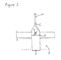
- Figure 2 shows on a larger scale a partial end view of the slab lifter of Figure 1;
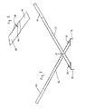
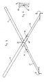
- Figure 3 and 4 show a slab lifter in which the bars have separate slab lifting portions, set for gripping 12 inch (0.30 m) and 36 inch (0.91 m) slabs respectively;
- Figure 5 shows on a larger scale the means employed in the slab lifter of Figures 3 and 4 for releasably securing the two elements of the bar;
- Figure 6 shows an end view on a larger scale of the pivot at the axis of rotation of the bars in the slab lifter of Figures 3 and 4;
- Figure 7 shows separately in perspective a slab-gripping element and the lower part of the main element of a bar similar to those of the slab lifter of Figures 3 and 4 but with different means for releasably securing the two elements;
- Figures 8, 9 and 10 show in perspective other types of slab-gripping elements for use in association with the main bar element of Figure 7;
- Figure 11 shows a side view of a slab lifter in which the bars have separate handle portions;
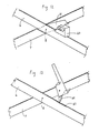
- Figure 12 is a partial view in perspective of the side of a slab lifter showing a resilient block of elastomer mounted laterally between the bars;
- Figure 13 is a partial view in perspective of the side of a slab lifter showing interaction between the bars by means of a pawl and ratchet;
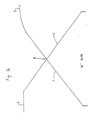
- Figure 14 is a diagram illustrating alternative shapes of handle.
- Figure 15 is a view in perspective of a preferred form of slab lifter.
- In the slab lifter shown by way of example in Figures 1 and 2, two flat bars M and N each have a right-angle twist C, D beyond which the bar is bent at an obtuse angle of 120 degrees at Y, Z to provide vertical slab-gripping portions each terminating in a short grab B, A. The other end of the bar is a handle E, F. The length of each bar from the twist C, D to the handle E, F is 1.12 metres (44 inches). The bars are loosely held together at Q by a 6.4 mm (

- Each bar has a series of other holes for coupling the bars together, representing adjustments to grip 0.30 metres, 0.46 metres and 0.91 metres (12 inch, 18 inch and 36 inch) slabs respectively instead of the 0.61 metres (24 inches) slab catered for by coupling at Q. Even when the bars are coupled through the holes for the 0.91 metre slab (i.e. the holes shown between Q and E and between Q and F, the distance from these holes to the slab-gripping portion of each bar at Y and Z is only 0.53 metres (204 inches) which is less than the distance from the holes to the handles E and F of 0.65 metres (254 inches).
- The slab-gripping portion of each bar beyond Y and Z is 63.5 mm (2) inches) long and terminates in a 3.2 mm (1/8th inch) grab at B and A respectively.
- Figure 1 shows an adjustable stabilizer fitted to one bar between the twist C and the beginning of Y of the slab-gripping portion. The stabilizer, the fitting of which is shown in more detail in Figure 2, consists of an 0.18 metre (7) inches) long piece of 32 mm (1: inch) channel iron with the top side angled at I to fit the angle of the bar between C and Y and with the bottom side J horizontal to bear on the top of the slab. The top side has a centrally positioned slot 6.4 mm (3 inch) wide extending in the direction of the bar for a length of 25 mm (1 inch). A 6.4 mm (

- The handles E and F, instead of being raised directly by a person on each, may be lifted by ropes passing through holes in the bars near the ends as shown in Figure 1. A third rope may be passed through a central washer hole K linked to the bolt at Q to drop the slab lifter down a pit or well for retrieving an object which can then be lifted using the ropes through the handles.
- In a slab lifter of alternative construction not shown in the drawings, the slab-gripping portion is 51 mm (2 inches) long and about the same thickness of the slab S, and has no terminal grabs. In all other respects this slab lifter is the same as the slab lifter shown in Figures 1 and 2. Whether a. stabilizer is fitted is a matter of choice and the slab lifter in its simplest construction has neither a stabilizer nor means for attaching one.
- In the slab lifter shown by way of example in Figures 3 to 6, each bar is composed of two releasably secured elements relatively moveable longitudinally for adjustment of length. The
main elements 10, 11 of each bar are of hollow steel of rectangular cross-section having a wall thickness of approximately 1/16th inch (1.6 mm) minimum 29) inches (0.75 m) long and are permanently pivoted together at a point 23 inches (0.58 m) from the handle end by means of arivet 13 passing through the pressed out section of the nearest wall of each hollow section and dressed down below the main inner face leaving the interior of the hollow section unobstructed. The slab-grippingportions section steel elements hollow sections 10, 11 respectively, If solid, these elements can be an 1/4th to 1 inch (6 to 25 mm) in thickness and inch to 2) inches (19 to 63 mm) in width. - As shown in more detail in Figure 5, the elements of the bars are secured together in the desired relative position by fixed spring pins 18 and 19 each mounted on an passing through a hole in the outer
hollow section 10, 11 into ahole 20 which is one of a series in predetermined desired locations in theinner element elements portions hollow element 10, 11 to the required position to take 36 inch, 24 inch, 18 inch or 12 inch slabs and are secured in the correct position by the spring pins 18, 19. - In Figures 7 to 10 the outer hollow element 11 and the
inner elements portions holes stabilizer 30 to bear on the horizontal surface of the slab. The slab-gripping blades or forks of the two arms of the slab lifter may be parallel (vertical) in the gripping position or they can "toe in" at the bottom by 2 or 5 degrees out of upright. - In the slab lifter shown by way of example in Figure 11 the
main parts holes main parts portions handle elements 10, 11 of the bars are formed of steel hollow section similar to that used for themain parts 10,11 of the bars in Figures 3 and 4 and they are releasably secured to themain parts spring clips - This enables the distance from the axis of rotation (e.g. 36 in Figure 11) to the
handle - The slab-gripping portion of the bars as shown in any of the Figures 1, 3 and 4, 7, and 11 may be the same or different on the two bars and each may have any of the configurations described above or shown in Figures 1 and 2 and any of Figures 7 to 10.
- Figures 12 and 13 illustrate by way of example the provision of means capable of interacting with both
bars rotation 8 so as to maintain them releasably in a slab-gripping posi- . tion. In Figure 12 a block 40 of firm elastomeric material is mounted on a plate 41 which is secured to the slab lifter at the axis ofrotation 8. When thebars 6, are gripping a slab the block 40 is compressed sufficiently to maintain them in that in position. To engage or release the slab, the ends of the bars are momentarily moved to compress the block 40 further. The plate 41 retains the block 40 in position when the slab lifter is not in use. It has one metal stop which fits under the upper bar (7 in Figure 12). The resilient understop may alternatively be formed of spring steel instead of elastomeric material as in block 40. - In Figure 13 a counterbalanced
pawl 42 is rotatably mounted on theupper bar 7 and interacts with aratchet 43 on the edge of thelower bar 6. The pawl is formed with a handle to facilitate release from the ratchet and with a stop of either side so that it cannot turn further than its workable arc. The tooth of the pawl automatically selects the correct serration of the ratchet when a slab is gripped and the handles of the slab lifter are raised. It then remains in position gripped to the slab if the operators remove their hands from the handles. Where the slab lifter has a series of holes in the bars to choose from as the axis of rotation, as shown for example in Figures 1 and 11, a corresponding series of holes is required in one of the bars for mounting the pawl (these holes conveniently being of a smaller size for ease of identification) and corresponding lengths of the other bar must accordingly be serrated to form the requisite ratchet. - Figure 14 is a diagram showing how an outwardly
curved handle 5 or a horizontally sethandle 4 may be provided on a slab lifter for lifting a 36 inch slab at an angle B between thebars rotation 8. - Figure 15 shows a preferred form of slab lifter, generally efficient to use and relatively cheap to produce, which comprises two straight solid flat bars as described with reference to Figure 1 but each with an angled lower end on to which is welded a short 0.1 metre (4 inch) piece of 50 mm x 50 mm (2 inch x 2 inch) of angle iron.
- Alternatively a simple slab lifter with pivot holes as seen in Figure 1, can be made up with two hollow section bars (M N), the grab element can be formed by inserting any type of the grab elements (similar to those shown in Figures 7, 8, 9 and 10) but with shorter insert bars which slide inside the hollow sections and are fixed securely.
Claims (10)
Applications Claiming Priority (4)
| Application Number | Priority Date | Filing Date | Title |
|---|---|---|---|
| GB8230533 | 1982-10-26 | ||
| GB8230533 | 1982-10-26 | ||
| GB08312300A GB2129359A (en) | 1982-10-26 | 1983-05-05 | Slab lifter |
| GB8312300 | 1983-05-05 |
Publications (3)
| Publication Number | Publication Date |
|---|---|
| EP0109765A2 EP0109765A2 (en) | 1984-05-30 |
| EP0109765A3 EP0109765A3 (en) | 1985-01-23 |
| EP0109765B1 true EP0109765B1 (en) | 1987-04-08 |
Family
ID=26284224
Family Applications (1)
| Application Number | Title | Priority Date | Filing Date |
|---|---|---|---|
| EP83306394A Expired EP0109765B1 (en) | 1982-10-26 | 1983-10-21 | Slab lifter |
Country Status (4)
| Country | Link |
|---|---|
| US (1) | US4572566A (en) |
| EP (1) | EP0109765B1 (en) |
| DE (1) | DE3370770D1 (en) |
| GB (1) | GB2129359A (en) |
Families Citing this family (25)
| Publication number | Priority date | Publication date | Assignee | Title |
|---|---|---|---|---|
| FR2576619B1 (en) * | 1985-01-25 | 1988-11-10 | Koehl Jean Marie | EDGING APPARATUS, SELF-LOCKING PAVERS OR THE LIKE. |
| EP0189356B1 (en) * | 1985-01-25 | 1992-10-21 | Jean-Marie Gérard René Koehl | Device for laying kerbs, interlocking paving stones and the like |
| GB8923779D0 (en) * | 1989-10-21 | 1989-12-06 | Kinzett Ian R | Lifting tool |
| GB2257683B (en) * | 1991-06-25 | 1994-10-12 | Geoffrey Allan Cole | A single lifter |
| EP0615021A1 (en) * | 1993-03-01 | 1994-09-14 | David John Jones | Lifting device |
| FR2705629B1 (en) * | 1993-05-24 | 1995-07-28 | Raimbault Marcel | Motorized wheeled vehicle for gripping and placing heavy items. |
| US5435611A (en) * | 1994-07-11 | 1995-07-25 | Campbell; David K. | Aluminum can handling tongs |
| US5871242A (en) * | 1995-11-03 | 1999-02-16 | Whitney; Denzil | Carton, box and bulk material lifting device |
| US5727828A (en) * | 1996-12-30 | 1998-03-17 | Jones; Richard | Adjustable garden tool apparatus |
| AU740186B2 (en) * | 1997-12-18 | 2001-11-01 | Plasterboard Lifting Tools Pty Ltd | Sheet material supporting apparatus |
| US6276732B1 (en) * | 2000-01-20 | 2001-08-21 | Omni-Lift U.S.A. | Lifting device |
| US6325432B1 (en) * | 2000-08-01 | 2001-12-04 | Elray J. Sensat | Cover lifting device |
| US6595566B1 (en) | 2001-07-13 | 2003-07-22 | Michael J. Donnan | Manhole cover lifter |
| AU2002301423C1 (en) * | 2001-10-11 | 2008-11-20 | The Austral Brick Company Pty Ltd | Device for Lifting Pavers |
| GB2386580B (en) * | 2002-03-21 | 2005-03-23 | Michael Frederick Leach | The bricky's mate |
| US20040135389A1 (en) * | 2003-01-09 | 2004-07-15 | Helms Robert J. | Lifting device for manhole tops and manhole covers |
| GB0302563D0 (en) * | 2003-02-05 | 2003-03-12 | Sev Trent Metering Service Ltd | Lid opening tool |
| GB2413543B (en) * | 2004-04-29 | 2007-07-11 | John Sanderson | Lifting device |
| DE102006041879A1 (en) * | 2006-09-06 | 2008-03-27 | Probst Greiftechnik Verlegesysteme Gmbh | Stone lifting device |
| US9493331B2 (en) | 2011-06-13 | 2016-11-15 | Jeffery D. Montgomery | Lifting and removal device |
| CN102659014A (en) * | 2012-05-18 | 2012-09-12 | 贵州建工集团第三建筑工程有限责任公司 | Sling special for concrete panel of reinforced earth retaining wall |
| CN103643619A (en) * | 2013-12-20 | 2014-03-19 | 济南黄河路桥工程公司 | Tool clamp for paving granite |
| US10161100B2 (en) * | 2014-12-18 | 2018-12-25 | 1128653 Ontario Ltd. | Adjustable manhole cover |
| US11001447B2 (en) * | 2018-09-05 | 2021-05-11 | Sleep Number Corporation | Lifting furniture |
| CN109625759A (en) * | 2019-02-03 | 2019-04-16 | 上海建工五建集团有限公司 | A kind of clipper tool and application method of carrying small-sized concrete prefabricated element |
Family Cites Families (15)
| Publication number | Priority date | Publication date | Assignee | Title |
|---|---|---|---|---|
| BE518538A (en) * | ||||
| US1344174A (en) * | 1919-10-13 | 1920-06-22 | Joseph Soeders | Lifting device or grapple |
| US1364128A (en) * | 1920-03-24 | 1921-01-04 | Calvin A Messinger | Brick-tongs |
| US1488725A (en) * | 1923-01-17 | 1924-04-01 | Ziloccki Giordano | Tongs |
| US1514863A (en) * | 1923-04-17 | 1924-11-11 | Rytell John Joseph | Weed puller |
| US1762486A (en) * | 1927-02-16 | 1930-06-10 | Roden Louis | Gate-valve-box cleaner |
| US1805604A (en) * | 1930-12-09 | 1931-05-19 | Straka Anton | Grappling hook |
| DE1032172B (en) * | 1955-05-17 | 1958-06-12 | Johannes Schneider | From a pincer-like, adjustable gripper member with movable jaws and legs hand-held device for loading bricks and. like |
| FR1200086A (en) * | 1956-08-14 | 1959-12-17 | Brick holder | |
| GB942840A (en) * | 1961-04-24 | 1963-11-27 | Robert Filmer Bridgland | A tongs-like device for lifting concrete slabs, kerbstones and the like |
| GB1000713A (en) * | 1963-06-04 | 1965-08-11 | John Greer | Improvements in or relating to lifting devices |
| GB1354500A (en) * | 1970-08-26 | 1974-06-05 | Perdue C I | Lifting devices |
| GB1400709A (en) * | 1971-09-02 | 1975-07-23 | Larsen A J | Device for laying of flagstones |
| FR2329549A1 (en) * | 1975-04-02 | 1977-05-27 | Gorsse Jacques | Breeze block lifting and transportation tool - has pin operated articulated flat section steel handles with pressure bar to maintain open position when not in use |
| AT355284B (en) * | 1978-10-27 | 1980-02-25 | Bluemel Franz Ing | PLIERS |
-
1983
- 1983-05-05 GB GB08312300A patent/GB2129359A/en not_active Withdrawn
- 1983-10-21 EP EP83306394A patent/EP0109765B1/en not_active Expired
- 1983-10-21 DE DE8383306394T patent/DE3370770D1/en not_active Expired
- 1983-10-25 US US06/545,256 patent/US4572566A/en not_active Expired - Fee Related
Also Published As
| Publication number | Publication date |
|---|---|
| DE3370770D1 (en) | 1987-05-14 |
| GB2129359A (en) | 1984-05-16 |
| US4572566A (en) | 1986-02-25 |
| EP0109765A2 (en) | 1984-05-30 |
| EP0109765A3 (en) | 1985-01-23 |
| GB8312300D0 (en) | 1983-06-08 |
Similar Documents
| Publication | Publication Date | Title |
|---|---|---|
| EP0109765B1 (en) | Slab lifter | |
| US4224751A (en) | Snow lifting device | |
| US20210214207A1 (en) | Multipurpose device | |
| US5791707A (en) | Snow removal device | |
| US4750249A (en) | Pipe scraping tool | |
| US7354084B2 (en) | Lifting device and method of use thereof | |
| US4791780A (en) | Roof rake | |
| US9670632B2 (en) | Shovel assembly and method of assembly thereof | |
| US6023811A (en) | Modular tool to remove grout | |
| CA2379713C (en) | Shovel | |
| US20060002759A1 (en) | Quick change pole end attachment connector | |
| US6237975B1 (en) | Snow shovel | |
| GB2171352A (en) | Lifting tool | |
| EP1817950B1 (en) | Manually operable tool | |
| EP2126255A2 (en) | Apparatus for lifting and handling articles | |
| US5509706A (en) | Paving stone, brick and tile tool | |
| US6698526B1 (en) | Weed-gripping pry tool | |
| EP1279780A2 (en) | Handling device | |
| AU2013101432A4 (en) | A Portable Bending Tool | |
| WO2003037061A1 (en) | Improved shovel | |
| AU2002301423B2 (en) | Device for Lifting Pavers | |
| AU647972B2 (en) | Scoop | |
| CN211337884U (en) | Stone carrying device | |
| CN209922150U (en) | Small-size steel cover plate handling tool | |
| DD141847A1 (en) | DEVICE FOR LAYING SINGLE PRE-FORMED CEILING COMPONENTS |
Legal Events
| Date | Code | Title | Description |
|---|---|---|---|
| PUAI | Public reference made under article 153(3) epc to a published international application that has entered the european phase |
Free format text: ORIGINAL CODE: 0009012 |
|
| AK | Designated contracting states |
Designated state(s): DE FR GB |
|
| PUAL | Search report despatched |
Free format text: ORIGINAL CODE: 0009013 |
|
| AK | Designated contracting states |
Designated state(s): DE FR GB |
|
| 17P | Request for examination filed |
Effective date: 19841217 |
|
| GRAA | (expected) grant |
Free format text: ORIGINAL CODE: 0009210 |
|
| AK | Designated contracting states |
Kind code of ref document: B1 Designated state(s): DE FR GB |
|
| PG25 | Lapsed in a contracting state [announced via postgrant information from national office to epo] |
Ref country code: FR Free format text: THE PATENT HAS BEEN ANNULLED BY A DECISION OF A NATIONAL AUTHORITY Effective date: 19870408 |
|
| REF | Corresponds to: |
Ref document number: 3370770 Country of ref document: DE Date of ref document: 19870514 |
|
| EN | Fr: translation not filed | ||
| PLBE | No opposition filed within time limit |
Free format text: ORIGINAL CODE: 0009261 |
|
| STAA | Information on the status of an ep patent application or granted ep patent |
Free format text: STATUS: NO OPPOSITION FILED WITHIN TIME LIMIT |
|
| 26N | No opposition filed | ||
| REG | Reference to a national code |
Ref country code: GB Ref legal event code: 746 |
|
| PG25 | Lapsed in a contracting state [announced via postgrant information from national office to epo] |
Ref country code: DE Effective date: 19890701 |
|
| GBPC | Gb: european patent ceased through non-payment of renewal fee | ||
| REG | Reference to a national code |
Ref country code: GB Ref legal event code: 210A |
|
| PGFP | Annual fee paid to national office [announced via postgrant information from national office to epo] |
Ref country code: GB Payment date: 19940928 Year of fee payment: 12 |
|
| PG25 | Lapsed in a contracting state [announced via postgrant information from national office to epo] |
Ref country code: GB Effective date: 19951021 |
|
| GBPC | Gb: european patent ceased through non-payment of renewal fee |
Effective date: 19951021 |