EP0109290A2 - System zum Entwässern mit einem Saugspalt mit regelbarer Breite - Google Patents
System zum Entwässern mit einem Saugspalt mit regelbarer Breite Download PDFInfo
- Publication number
- EP0109290A2 EP0109290A2 EP83306919A EP83306919A EP0109290A2 EP 0109290 A2 EP0109290 A2 EP 0109290A2 EP 83306919 A EP83306919 A EP 83306919A EP 83306919 A EP83306919 A EP 83306919A EP 0109290 A2 EP0109290 A2 EP 0109290A2
- Authority
- EP
- European Patent Office
- Prior art keywords
- channel
- plate
- wear
- suction
- wear strip
- Prior art date
- Legal status (The legal status is an assumption and is not a legal conclusion. Google has not performed a legal analysis and makes no representation as to the accuracy of the status listed.)
- Ceased
Links
- 239000000463 material Substances 0.000 claims abstract description 7
- 230000033001 locomotion Effects 0.000 claims description 12
- 210000005069 ears Anatomy 0.000 claims description 10
- 230000000712 assembly Effects 0.000 description 5
- 238000000429 assembly Methods 0.000 description 5
- 238000012423 maintenance Methods 0.000 description 2
- 238000000034 method Methods 0.000 description 2
- 239000000919 ceramic Substances 0.000 description 1
- 230000000694 effects Effects 0.000 description 1
- 238000003754 machining Methods 0.000 description 1
- 238000012986 modification Methods 0.000 description 1
- 230000004048 modification Effects 0.000 description 1
- 229920003023 plastic Polymers 0.000 description 1
- 239000004033 plastic Substances 0.000 description 1
Images

Classifications
-
- D—TEXTILES; PAPER
- D21—PAPER-MAKING; PRODUCTION OF CELLULOSE
- D21F—PAPER-MAKING MACHINES; METHODS OF PRODUCING PAPER THEREON
- D21F1/00—Wet end of machines for making continuous webs of paper
- D21F1/48—Suction apparatus
- D21F1/52—Suction boxes without rolls
- D21F1/523—Covers thereof
Definitions
- This invention relates to a suction dewatering system for a paper making machine of the type in which felt is passed over a suction slot defined by laterally-spaced wear strips.
- the invention is concerned, in particular, with an improved arrangement for adjusting the width of the suction slot by laterally shifting the relative positions of the wear strips.
- the aim of the invention is to provide an improved arrangement for adjusting the width of the suction slot of a dewatering system for a paper making machine, which arrangement is free of the disadvantages referred to above.
- the present invention provides a suction dewatering system for a paper making machine, the suction dewatering system comprising a suction device having a longitudinal opening adjacent to the path of material travel through the machine, the opening being connectible to a source of suction, elongate wear strips supported on opposite sides of the opening to define a suction slot therebetween, the suction slot being aligned with the opening, a channel extending longitudinally through one of the wear strips in a direction parallel to the longitudinal axis of the suction slot, and adjustment means movable longitudinally within the channel for laterally adjusting the position of said one wear strip relative to the other wear strip in order to vary the width of the suction slot.
- each of the wear strips has a channel extending longitudinally therethrough in a direction parallel to the longitudinal axis of the suction slot, and respective adjustment means are movable longitudinally within each channel for laterally adjusting the relative positions of the wear strips in order to vary the width of the suction slot.
- the suction device may have stationary mounting surfaces located on opposite sides of the opening, the elongate wear strips being supported on the mounting surfaces.
- the or each adjustment means includes guide members fixed relative to the mounting surface on which the associated wear strip is supported, the guide members being arranged to protrude into the associated channel.
- the or each adjustment means includes an elongate first plate laterally confined within the associated channel, and movable longitudinally in relation to the associated wear strip.
- the or each first plate has cam slots therein which extend obliquely with respect to the longitudinal axis of the suction slot, the associated guide members being engageable with the cam slots, whereupon longitudinal movement of the or each first plate within its channel will be accompanied by lateral movement of the associated wear strip relative to the other wear strip as a result of the engagement of the guide members with the associated cam slots.
- the or each first plate may be supported on internal shoulders formed within the associated channel at a location above the mounting surface supporting the associated wear strip.
- the system may further comprise locking means for releasably fixing the wear strips to one another.
- the locking means is arranged to force the or each first plate downwardly against the associated internal shoulders thereby to clamp the associated wear strip downwardly onto its respective mounting surface.
- the locking means comprises a respective elongate second plate supported within the or each channel on the associated first plate, the or each second plate having locking slots therein with resilient locking ears adjacent thereto, the associated guide members protruding through said locking slots, the or each second plate being movable longitudinally relative to the associated first plate between a "clamp” position in which the associated locking ears resiliently coact with the associated guide members to exert downward force on said first plate to thereby fix the associated wear strip onto its mounting surface, and a "release” position in which said downward force is sufficiently relieved to allow movement ot the associated wear strip relative to its mounting surface.
- the wear strips of the present invention have the same design, with centrally-located longitudinally-extending guide channels.
- Cam-type adjusting and locking assemblies operate within the guide channels to effect lateral adjustment of the wear strips, and to releasably fix the wear strips at their adjusted positions.
- Worn wear strips may be longitudinally removed from their respective adjusting and locking assemblies in directions parallel to the associated suction slot, and fresh wear strips may be reinserted in the same direction, all without disturbing other machine components.
- inventory costs are reduced significantly.
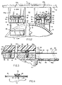
- the drawings show a suction device in the form of a pipe 10.
- the pipe 10 has a longitudinal opening 12 extending transversely with respect to the path of travel "P" of an overlying felt 14.
- the pipe 10 is adapted for connection, in a conventional well known manner, to a source of suction (not shown).
- Stationary elongated lands 16 extend along opposite sides of the opening 12.
- the lands 16 define mounting surfaces 18.
- Identical elongated wear strips 20a and 20b are adapted to be supported on the mounting surfaces 18.
- the wear strips 20a and 20b are spaced apart to define an elongated suction slot 22 which overlies, and is in alignment with, the pipe opening 12.
- the wear strips 20a and 20b are made from ceramic or plastics material, with their upper surfaces 24a and 24b being arranged to support the felt 14 as it moves along the paper making machine.
- the ends of the suction slot 22 may be blocked by conventional closure elements such as deckles (not shown).
- Each wear strip 20a or 20b is provided with a channel 26 facing downwardly toward its respective mounting surface 18.
- the channels 26 have interior ledges 28 formed by inwardly protruding shoulders 30.
- Adjusting and locking assemblies 32 are located within the channels 26.
- Each assembly 32 includes a plurality of guide members 34 spaced along the lands 16.
- the guide members 34 protrude upwardly from the mounting surfaces 18 between the interior channel shoulders 30.
- the guide members 34 conveniently comprise shoulder screws with enlarged heads 36.
- Elongate adjusting plates 38 extend through the channels 26.
- the adjusting plates 38 are supported on the ledges 28, and are provided with cam slots 40 which extend obliquely with respect to the longitudinal axis of the suction slot 22.
- the adjusting plates 38 are prevented from moving laterally in relation to their respective wear strips 20a and 20b by the side walls of the channels 26.
- Locking plates 42 lie on the adjusting plates 38.
- the locking plates 42 have elongate locking slots 44 whose longitudinal axes are parallel to the longitudinal axis of the suction slot 22 and to the longitudinal axes of the channels 26.
- the locking slots 42 are at least partially in registration with the underlying cam slots 40.
- the locking slots 42 are at least partially bounded by upwardly-inclined, resilient locking ears 46.
- the ears 46 are stamped, or otherwise integrally formed, from the locking plate material.
- the guide members 34 protrude through both the cam slots 40 and the locking slots 46, with their heads 36 being located adjacent to the locking ears 46.
- the adjusting plates 38 and the locking plates 42 have ends which protrude beyond the ends of the wear strips 20a and 20b to overlie brackets 48 fixed to the end of the suction pipe 10.
- the brackets 48 are each provided with a set of locking holes 48a, and with a set of adjusting holes 48b.
- the protruding end of each adjusting plate 38 has an adjusting hole 50, and an elongate access slot 52.
- the protruding end of each locking plate 42 has a locking hole 54.
- Each locking plate 42 is movable longitudinally between a "clamp” position, as shown in Fig. 4 and the right-hand side of Fig. 1, and a "release” position, as shown in Fig. 3 and the left-hand side of Fig. 1.
- a locking plate 42 When in the clamp position, a locking plate 42 has been moved to the right (as seen in Fig. 4), thereby pulling the locking ears 46 beneath the enlarged heads 36 of the guide members 34.
- the locking ears 46 coact resiliently with the heads 36 to produce a downward force which acts, through the underlying adjusting plate 38 and its supporting ledges 28, to clamp the associated wear strip 20a or 20b in a fixed position on its mounting surface 18.
- the associated adjusting plate 38 With a locking plate 42 in its release position, the associated adjusting plate 38 can be moved longitudinally in either direction within its channel 26. As this occurs, the guide members 34 coact with the oblique cam slots 40 to move the adjusting plate 38 and the associated wear strip 20a or 20b laterally, thereby changing the width of the suction slot 22. Once the proper adjustment is achieved, the locking plate 42 is returned to its clai,:p position to fix all components in place.
- Each locking plate 42 can moved manually by first inserting a tool 56 (see Fig. 3) through the locking hole 54 and through the access slot 52 in the underlying adjustment plate 38 and into one of the locking holes 48a in the bracket 48, and then simply rocking the tool in the appropriate direction.
- the adjusting plate 38 can be shifted in the same way by inserting the tool 56 through the adjusting hole 50 into one of the underlying holes 48b in the bracket 48.
- the wear strips 20a and 20b are identical, they can be interchanged one for the other at any location along the machine.
- the longitudinal channels 26 enable worn wear strips 20a and 20b to be withdrawn from their respective mounting surfaces 18, while allowing the adjusting and locking assemblies 32 to remain in place; and enable new wear strips to be inserted thereafter, again without having to dismantle the assemblies 32.
- the wear strips 20a and 20b may be withdrawn and replaced by moving them longitudinally in directions parallel to the suction slot 22, thus further facilitating maintenance procedures.
Landscapes
- Paper (AREA)
Applications Claiming Priority (2)
| Application Number | Priority Date | Filing Date | Title |
|---|---|---|---|
| US440961 | 1982-11-12 | ||
| US06/440,961 US4459176A (en) | 1982-11-12 | 1982-11-12 | Dewatering system with adjustable width suction slots |
Publications (2)
| Publication Number | Publication Date |
|---|---|
| EP0109290A2 true EP0109290A2 (de) | 1984-05-23 |
| EP0109290A3 EP0109290A3 (de) | 1985-05-15 |
Family
ID=23750924
Family Applications (1)
| Application Number | Title | Priority Date | Filing Date |
|---|---|---|---|
| EP83306919A Ceased EP0109290A3 (de) | 1982-11-12 | 1983-11-11 | System zum Entwässern mit einem Saugspalt mit regelbarer Breite |
Country Status (5)
| Country | Link |
|---|---|
| US (1) | US4459176A (de) |
| EP (1) | EP0109290A3 (de) |
| JP (1) | JPS6035475B2 (de) |
| BR (1) | BR8306220A (de) |
| CA (1) | CA1218548A (de) |
Families Citing this family (15)
| Publication number | Priority date | Publication date | Assignee | Title |
|---|---|---|---|---|
| US5830322A (en) * | 1996-02-13 | 1998-11-03 | Thermo Fibertek Inc. | Velocity induced drainage method and unit |
| US5922173A (en) * | 1997-04-22 | 1999-07-13 | Thermo Fibertek Inc. | Paper forming activity control with lifting variable inertial stimulation blades with limited-vent indented-surfaces |
| US5980692A (en) * | 1997-12-22 | 1999-11-09 | Thermo Web Systems, Inc. | Removable doctor blade holder |
| US6312563B1 (en) | 1997-12-22 | 2001-11-06 | Thermo Web Systems, Inc. | Removable doctor blade holder |
| AU2001296693A1 (en) * | 2000-10-10 | 2002-04-22 | Appleton International, Inc. | Variable frequency fourdrinier gravity foil box |
| DE10115422A1 (de) * | 2001-03-29 | 2002-10-02 | Voith Paper Patent Gmbh | Befestigungsvorrichtung |
| US6372093B1 (en) | 2001-04-26 | 2002-04-16 | Wilbanks International, Inc. | Adjustable foil apparatus for papermaking machine |
| US20060185812A1 (en) * | 2005-02-22 | 2006-08-24 | John Rotherham | Removable doctor blade holder with lockable mount |
| WO2007090045A1 (en) * | 2006-01-31 | 2007-08-09 | Kadant Inc. | Keep for doctor blade holder |
| HUE025276T2 (en) | 2006-02-03 | 2016-02-29 | Y Lopez Caram Luis Fernando Cabrera | Fibreboard making equipment and method for maintaining hydrodynamic processes for producing paper sheets |
| US7867364B2 (en) * | 2006-08-16 | 2011-01-11 | Kadant Inc. | Doctor blade holder permitting efficient assembly of doctor assemblies and replacement of doctor blades |
| CN101821450B (zh) * | 2007-12-06 | 2013-04-24 | 卡登特网络体系股份有限公司 | 刮刀刀架 |
| US8163136B2 (en) | 2010-12-16 | 2012-04-24 | FC Papel LLC | Energy saving papermaking forming apparatus system, and method for lowering consistency of fiber suspension |
| MX2014000730A (es) | 2011-07-21 | 2015-05-15 | Fcpapel Llc | Aparato, sistema y metodo formadores para la fabricacion de papel ahorradores de energia para disminuir la consistencia de la suspension de fibras. |
| US9593451B2 (en) * | 2014-11-10 | 2017-03-14 | Richard L House | Movable foil blade for papermaking on a fourdrinier, including the lead blade on the forming board box |
Family Cites Families (7)
| Publication number | Priority date | Publication date | Assignee | Title |
|---|---|---|---|---|
| US3645844A (en) * | 1968-04-22 | 1972-02-29 | Lodding Engineering Corp | Mounting means for foil type and similar elements |
| GB1229514A (de) * | 1969-08-04 | 1971-04-21 | ||
| US3836428A (en) * | 1972-08-25 | 1974-09-17 | Albany Int Corp | Adjustable slot suction box cover |
| FI256373A7 (de) * | 1973-08-15 | 1975-02-16 | Ahlstroem Oy | |
| GB1559277A (en) * | 1975-11-06 | 1980-01-16 | Jwi Ltd | Stock formation in a paper making process |
| US4278497A (en) * | 1980-02-14 | 1981-07-14 | Albany International Corp. | Suction dewatering system with automatically adjusting suction slot |
| US4280869A (en) * | 1980-02-14 | 1981-07-28 | Albany International Corp. | Suction dewatering system with cam actuated adjustable slot |
-
1982
- 1982-11-12 US US06/440,961 patent/US4459176A/en not_active Expired - Fee Related
-
1983
- 1983-11-10 CA CA000440949A patent/CA1218548A/en not_active Expired
- 1983-11-11 BR BR8306220A patent/BR8306220A/pt unknown
- 1983-11-11 EP EP83306919A patent/EP0109290A3/de not_active Ceased
- 1983-11-12 JP JP58211726A patent/JPS6035475B2/ja not_active Expired
Also Published As
| Publication number | Publication date |
|---|---|
| JPS6035475B2 (ja) | 1985-08-14 |
| BR8306220A (pt) | 1984-06-19 |
| US4459176A (en) | 1984-07-10 |
| JPS59100787A (ja) | 1984-06-11 |
| EP0109290A3 (de) | 1985-05-15 |
| CA1218548A (en) | 1987-03-03 |
Similar Documents
| Publication | Publication Date | Title |
|---|---|---|
| EP0109290A2 (de) | System zum Entwässern mit einem Saugspalt mit regelbarer Breite | |
| DE60110685T2 (de) | Montageanordnung für Ventile | |
| US4909906A (en) | Cover piece for a suction box with wavelike or zigzag passage | |
| EP0438685B1 (de) | Former in einer Papiermaschine | |
| US3337394A (en) | Foil type drainage apparatus for paper making machines | |
| EP0232604B1 (de) | Stoffauflauf für eine Papiermaschine | |
| EP0659224B1 (de) | Vorrichtung zum befestigen einer schiene | |
| US3645844A (en) | Mounting means for foil type and similar elements | |
| US5630910A (en) | Clip fastener for a dewatering box | |
| WO2006007913A1 (de) | Sammelschienenhalter | |
| US4846387A (en) | Paper guide assembly for photographic processor | |
| DE19702647C1 (de) | Vorrichtung zum Herstellen von Querrippen-Rohren | |
| US4558398A (en) | Printed circuit board storage cabinet | |
| US5860373A (en) | Module for tufting tools | |
| DE19814771C2 (de) | Hauptleitungsabzweigklemme | |
| EP0103687B1 (de) | Klischeehalter für Tampondruckmaschinen | |
| US3713610A (en) | Mounting means for foil type and similar elements | |
| US4790245A (en) | Support assembly for a cylinder groove | |
| DE3636944C2 (de) | Montageeinrichtung für die Anbringung eines Gestelles von NH-Sicherungstrennern, NH-Sicherungsunterteilen oder dergleichen | |
| US4545273A (en) | Partition wall battery box puncher | |
| SU1357179A1 (ru) | Устройство дл регулировки плоских направл ющих | |
| ATE62796T1 (de) | Schublade od. dgl. mit mindestens einem verstellbaren trennschied. | |
| KR200360928Y1 (ko) | 직물 운반용 가이드 레일 | |
| DE3738655A1 (de) | Nadelbett fuer flach- und rundstrickmaschinen | |
| JP2505415Y2 (ja) | 織機における機掛装置 |
Legal Events
| Date | Code | Title | Description |
|---|---|---|---|
| PUAI | Public reference made under article 153(3) epc to a published international application that has entered the european phase |
Free format text: ORIGINAL CODE: 0009012 |
|
| AK | Designated contracting states |
Designated state(s): AT BE CH DE FR GB IT LI LU NL SE |
|
| PUAL | Search report despatched |
Free format text: ORIGINAL CODE: 0009013 |
|
| AK | Designated contracting states |
Designated state(s): AT BE CH DE FR GB IT LI LU NL SE |
|
| 17P | Request for examination filed |
Effective date: 19851014 |
|
| 17Q | First examination report despatched |
Effective date: 19861021 |
|
| R17C | First examination report despatched (corrected) |
Effective date: 19870310 |
|
| STAA | Information on the status of an ep patent application or granted ep patent |
Free format text: STATUS: THE APPLICATION HAS BEEN REFUSED |
|
| 18R | Application refused |
Effective date: 19880609 |
|
| RIN1 | Information on inventor provided before grant (corrected) |
Inventor name: GOODNOW, RONALD F. |