EP0108047B1 - Pusher-type oven - Google Patents
Pusher-type oven Download PDFInfo
- Publication number
- EP0108047B1 EP0108047B1 EP83890165A EP83890165A EP0108047B1 EP 0108047 B1 EP0108047 B1 EP 0108047B1 EP 83890165 A EP83890165 A EP 83890165A EP 83890165 A EP83890165 A EP 83890165A EP 0108047 B1 EP0108047 B1 EP 0108047B1
- Authority
- EP
- European Patent Office
- Prior art keywords
- sliding
- rails
- furnace
- pusher
- shoes
- Prior art date
- Legal status (The legal status is an assumption and is not a legal conclusion. Google has not performed a legal analysis and makes no representation as to the accuracy of the status listed.)
- Expired
Links
Images

Classifications
-
- F—MECHANICAL ENGINEERING; LIGHTING; HEATING; WEAPONS; BLASTING
- F27—FURNACES; KILNS; OVENS; RETORTS
- F27B—FURNACES, KILNS, OVENS, OR RETORTS IN GENERAL; OPEN SINTERING OR LIKE APPARATUS
- F27B9/00—Furnaces through which the charge is moved mechanically, e.g. of tunnel type; Similar furnaces in which the charge moves by gravity
- F27B9/14—Furnaces through which the charge is moved mechanically, e.g. of tunnel type; Similar furnaces in which the charge moves by gravity characterised by the path of the charge during treatment; characterised by the means by which the charge is moved during treatment
- F27B9/20—Furnaces through which the charge is moved mechanically, e.g. of tunnel type; Similar furnaces in which the charge moves by gravity characterised by the path of the charge during treatment; characterised by the means by which the charge is moved during treatment the charge moving in a substantially straight path tunnel furnace
- F27B9/26—Furnaces through which the charge is moved mechanically, e.g. of tunnel type; Similar furnaces in which the charge moves by gravity characterised by the path of the charge during treatment; characterised by the means by which the charge is moved during treatment the charge moving in a substantially straight path tunnel furnace on or in trucks, sleds, or containers
-
- F—MECHANICAL ENGINEERING; LIGHTING; HEATING; WEAPONS; BLASTING
- F27—FURNACES; KILNS; OVENS; RETORTS
- F27B—FURNACES, KILNS, OVENS, OR RETORTS IN GENERAL; OPEN SINTERING OR LIKE APPARATUS
- F27B9/00—Furnaces through which the charge is moved mechanically, e.g. of tunnel type; Similar furnaces in which the charge moves by gravity
- F27B9/14—Furnaces through which the charge is moved mechanically, e.g. of tunnel type; Similar furnaces in which the charge moves by gravity characterised by the path of the charge during treatment; characterised by the means by which the charge is moved during treatment
- F27B9/20—Furnaces through which the charge is moved mechanically, e.g. of tunnel type; Similar furnaces in which the charge moves by gravity characterised by the path of the charge during treatment; characterised by the means by which the charge is moved during treatment the charge moving in a substantially straight path tunnel furnace
- F27B9/22—Furnaces through which the charge is moved mechanically, e.g. of tunnel type; Similar furnaces in which the charge moves by gravity characterised by the path of the charge during treatment; characterised by the means by which the charge is moved during treatment the charge moving in a substantially straight path tunnel furnace on rails, e.g. under the action of scrapers or pushers
-
- F—MECHANICAL ENGINEERING; LIGHTING; HEATING; WEAPONS; BLASTING
- F27—FURNACES; KILNS; OVENS; RETORTS
- F27D—DETAILS OR ACCESSORIES OF FURNACES, KILNS, OVENS, OR RETORTS, IN SO FAR AS THEY ARE OF KINDS OCCURRING IN MORE THAN ONE KIND OF FURNACE
- F27D3/00—Charging; Discharging; Manipulation of charge
- F27D3/02—Skids or tracks for heavy objects
- F27D3/022—Skids
- F27D3/024—Details of skids, e.g. riders
Definitions
- the invention relates to a push furnace with rails for sliding shoes that carry the material to be transported through the furnace, and with sliding elements that reduce the friction between the rails and the sliding shoes.
- Such pusher furnaces are generally used for the annealing treatment of bars made of aluminum or aluminum alloys, the bars, which can have a weight of several tons, are usually foamed through the furnace with the aid of a hydraulic pusher.
- FR-A-2498308 which have an essentially U-shaped cross section of sliding shoes to be provided on its inner web side with at least one sliding element, which is preferably designed as a sliding strip running lengthwise in the thrust direction and consisting of an alloy with colloidal graphite as a self-lubricant.
- the arrangement or attachment of the sliding elements on the sliding shoes has various disadvantages.
- the sliding shoes are loaded outside the furnace, then have to pass through the furnace and finally have to leave the furnace again, they are exposed to a shock-like temperature change, which places considerable stress on the sliding elements. If there are differences in height at the unavoidable rail joints, the sliding elements can easily break out on their end faces. There is also a risk of breakage for the sliding elements due to shock loads, e.g. when placing heavy ingots on the sliding shoes. The material waste that occurs when the sliding elements break out on the one hand and the normal material abrasion on the other hand inevitably remain on the rails and naturally impair the sliding properties of the sliding elements of the subsequent sliding shoes. Finally, there is a risk that loosening the fasteners, e.g. the screws for which the sliding elements on the sliding shoes block the transport of shoes inside or outside the furnace, which can result in severe damage to the entire furnace by the upright bars being tipped over.
- the fasteners e.g. the screws for which the sliding elements on the sliding shoes block the transport of shoes inside or outside the furnace,
- the invention is therefore based on the object of eliminating these deficiencies and creating a pusher furnace of the type described in the introduction, in which the friction between the rails and the slide shoes and also the breakaway forces at the start of the pusher process are significantly reduced without endangering the slide elements or have to accept an impairment of their sliding properties or other damage.
- the invention solves this problem in that the sliding elements are designed as a plurality of sliding plates inserted one behind the other in flat recesses on the upper side of the rails.
- the sliding elements are no longer on the inside or Bottom of the web of the slide shoes attached, but arranged on the top of the rails. They therefore always remain in the same place, i.e. at the same operating temperature, and are not subjected to shock-like changes in temperature.
- the sliding plates arranged in two longitudinal rows have surface grooves that run obliquely to the longitudinal direction of the rails, the surface grooves of the sliding plates in one longitudinal row being arranged in mirror image of the surface grooves of the sliding plates forming the other longitudinal row.
- the abrasion and the like. discharged from the sliding shoes over it into the free space outside the relevant sliding plate, the mirror-image arrangement of the surface grooves causing a cancellation of frictional forces occurring transversely to the longitudinal direction of the rail.
- a particularly advantageous embodiment is achieved in that the sliding plates each cover the rail joint, so that slight differences in height of the rail pieces in the joint region are compensated for.
- Heating burners 2 are installed in the ceiling of a furnace 1.
- a ceiling fan 3 and gas baffles 4 are provided for circulating the furnace gases.
- Rails 5 are mounted on supports on the bottom of the furnace 1, on which sliding shoes 6 can be moved, which hit the material to be treated, for example rolled bars 7. 2, the rails 5 have flat recesses 8 on their upper side, in which sliding elements in the form of sliding plates 9 are inserted.
- the sliding plates 9 are arranged on each rail 5 in two longitudinal rows and are spaced within the rows and between them, so that free spaces are formed in which abrasion and the like. can collect without affecting the sliding properties.
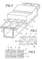
- the rails 5 consist of sections 5a (Fig. 3), wherein the rail joint is bridged by sliding plates 9. As shown in FIG. 4, the sliding plates 9 forming one longitudinal row can also be offset in the longitudinal direction of the rail compared to the sliding plates 9a arranged in the other longitudinal row.
- the cross-sectional shape of the rails can be selected differently, the only important thing is that there is a flange on both long sides, which the shoes can grip under.
- the sliding plates 9 and 9a preferably consist of a sintered material in a special alloy.
Description
Die Erfindung bezieht sich auf einen Stoßofen mit Schienen für Gleitschuhe, die das durch den Ofen zu transportierende Behandlungsgut tragen, und mit die Reibung zwischen den Schienen und den Gleitschuhen verringernden Gleitelementen.The invention relates to a push furnace with rails for sliding shoes that carry the material to be transported through the furnace, and with sliding elements that reduce the friction between the rails and the sliding shoes.
Derartige Stoßöfen dienen in der Regel zur Glühbehandlung von Barren aus Aluminium oder Aluminiumlegierungen, wobei die Barren, die ein Gewicht von mehreren Tonnen aufweisen können, meist mit Hilfe einer hydraulischen Stoßvorrichtung durch den Ofen geschohen werden. Um die bei Beginn des Stoßvorganges auftretenden Losbrechkräfte herabzusetzen, eine ruckfreie Verschiehung der hochbelasteten Gleitschuhe auf den Schienen zu erreichen und eine Ver-schleißminderung herbeizuführen, ist bereits vorgeschlagen worden (FR-A- 2498308), die einen im wesentlichen U-förmigen Querschnitt besitzenden Gleitschuhe auf ihrer inneren Stegseite mit mindestens einem Gleitelement zu versehen, das vorzugsweise als in Schubrichtung längsverlaufende Gleitleiste ausgebildet ist und aus einer Legierung mit Kolloidalgraphit als Selbstschmiermittel besteht. Die Anordnung bzw. Befestigung der Gleitelemente an den Gleitschuhen bringt aber verschiedene Nachteile mit sich.Such pusher furnaces are generally used for the annealing treatment of bars made of aluminum or aluminum alloys, the bars, which can have a weight of several tons, are usually foamed through the furnace with the aid of a hydraulic pusher. In order to reduce the breakaway forces that occur at the start of the impact process, to achieve a jolt-free displacement of the highly loaded sliding shoes on the rails and to reduce wear, it has already been proposed (FR-A-2498308), which have an essentially U-shaped cross section of sliding shoes to be provided on its inner web side with at least one sliding element, which is preferably designed as a sliding strip running lengthwise in the thrust direction and consisting of an alloy with colloidal graphite as a self-lubricant. The arrangement or attachment of the sliding elements on the sliding shoes has various disadvantages.
Da die Gleitschuhe außerhalb des Ofens beladen werden, dann den Ofen durchlaufen und schließlich den Ofen wieder verlassen müssen, sind sie einem schockartigen Temperaturwechsel ausgesetzt, der eine beträchtliche Beanspruchung der Gleitelemente mit sich bringt. Bei Höhenunterschieden an den unvermeidbaren Schienenstößen können die Gleitelemente an ihren Stirnflächen leicht ausbrechen. Bruchgefahr für die Gleitelemente besteht auch durch Stoßbelastungen, z.B. beim Auflegen von tonnenschweren Barren auf die Gleitschuhe. Der bei einem Ausbrechen der Gleitelemente auftretende Materialabfall einerseits und der normale Materialabrieb anderseits bleiben zwangsläufig auf den Schienen liegen und beeinträchtigen selbstverständlich die Gleiteigenschaften der Gleitelemente der nachfolgenden Gleitschuhe. Schließlich besteht die Gefahr, daß es durch Lockerung der Befestigungsmittel, z.B. der Schrauben, für die Gleitelemente an den Gleitschuhen zu einem Blockieren des Schuhtransportes innerhalb oder außerhalb des Ofens kommt, was schwere Beschädigungen des ganzen Ofens durch Umkippen der hochkant stehenden Barren zur Folge haben kann.Since the sliding shoes are loaded outside the furnace, then have to pass through the furnace and finally have to leave the furnace again, they are exposed to a shock-like temperature change, which places considerable stress on the sliding elements. If there are differences in height at the unavoidable rail joints, the sliding elements can easily break out on their end faces. There is also a risk of breakage for the sliding elements due to shock loads, e.g. when placing heavy ingots on the sliding shoes. The material waste that occurs when the sliding elements break out on the one hand and the normal material abrasion on the other hand inevitably remain on the rails and naturally impair the sliding properties of the sliding elements of the subsequent sliding shoes. Finally, there is a risk that loosening the fasteners, e.g. the screws for which the sliding elements on the sliding shoes block the transport of shoes inside or outside the furnace, which can result in severe damage to the entire furnace by the upright bars being tipped over.
Somit liegt der Erfindung die Aufgabe zugrunde, diese Mängel zu beseitigen und einen Stoßofen der eingangs geschilderten Art zu schaffen, bei dem die Reibung zwischen den Schienen und den Gleitschuhen und auch die Losbrechkräfte bei Beginn des Stoßvorganges wesentlich herabgesetzt sind, ohne eine Gefährdung der Gleitelemente oder eine Beeinträchtigung ihrer Gleiteigenschaften oder sonstige Beschädigungen in Kauf nehmen zu müssen.The invention is therefore based on the object of eliminating these deficiencies and creating a pusher furnace of the type described in the introduction, in which the friction between the rails and the slide shoes and also the breakaway forces at the start of the pusher process are significantly reduced without endangering the slide elements or have to accept an impairment of their sliding properties or other damage.
Die Erfindung löst die gestellte Aufgabe dadurch, daß die Gleitelemente als eine Mehrzahl von in flachen Ausnehmungen an der Oberseite der Schienen hintereinander eingesetzten Gleitplatten ausgebildet sind.The invention solves this problem in that the sliding elements are designed as a plurality of sliding plates inserted one behind the other in flat recesses on the upper side of the rails.
Die Gleitelemente sind also nicht mehr an der Innenbzw. Unterseite des Steges der Gleitschuhe befestigt, sondern an der Oberseite der Schienen angeordnet. Sie verbleiben daher immer an derselben Stelle, also auf gleichbleibender Betriebstemperatur, und werden nicht durch schockartigen Temperat urwechsel beansprucht. Zwischen den Gleitelementen bzw. Gleitplatten verbleibt genug Freiraum zur Aufnahme des Materialabriebs und von körnigem Materialabfall, so daß die Gleiteigenschaften nicht beeinträchtigt werden, da die Gleitschuhe auf der von Verunreinigungen freien Oberfläche der Gleitplatten gleiten und sich der Abrieb u.dgl. in dem von der Gleitfläche überragten Freiraum sammeln kann. Eine Beschädigung der Gleitplatten im Bereich der Schienenstöße ist selbstverständlich ausgeschlossen, da die Gleitplatten in den Schienen selbst angeordnet sind und nicht über diese hinweg bewegt werden müssen. Sollten sich die Befestigungsschrauben od.dgl. lockern, so wird dadurch der Schubvorgang der Gleitschuhe durch den Ofen nicht beeinträchtigt, da die bei der Bewegung der Gleitschuhe an den Gleitplatten auftretenden Reibungskräften von der Ausnehmungswand auf die Schiene übertragen und die Befestigungselemente selbst nicht beansprucht werden. Selbst zu Bruch gegangene Gleitplatten erfüllen in den für sie vorgesehenen Ausnehmungen problemlos ihre Aufgabe.The sliding elements are no longer on the inside or Bottom of the web of the slide shoes attached, but arranged on the top of the rails. They therefore always remain in the same place, i.e. at the same operating temperature, and are not subjected to shock-like changes in temperature. There is enough space between the sliding elements or sliding plates to accommodate the material abrasion and granular material waste, so that the sliding properties are not impaired, since the sliding shoes slide on the surface of the sliding plates free of contaminants and the abrasion and the like. can collect in the space dominated by the sliding surface. Damage to the slide plates in the area of the rail joints is, of course, ruled out, since the slide plates are arranged in the rails themselves and do not have to be moved over them. If the mounting screws or the like. loosen, the pushing process of the sliding shoes through the furnace is not impaired, since the frictional forces occurring during the movement of the sliding shoes on the sliding plates are transmitted from the recess wall to the rail and the fastening elements themselves are not stressed. Even sliding plates that have broken can easily do their job in the recesses provided for them.
In weiterer Ausbildung der Erfindung weisen die in zwei Längsreihen angeordneten Gleitplatten schräg zur Schienenlängsrichtung verlaufende Oberflächennuten auf, wobei die Oberflächennuten der Gleitplatten in der einen Längsreihe spiegeldbildlich zu den Oberflächennuten der die andere Längsreihe bildenden Gleitplatten angeordnet sind. Durch diese Oberflächennuten wird der Abrieb u.dgl. von den darübergleitenden Gleitschuhen in den Freiraum außerhalb der betreffenden Gleitplatte abgeführt, wobei die spiegelbildliche Anordnung der Oberflächennuten eine Aufhebung von quer zur Schienenlängsrichtung auftretenden Reibungskräften bewirkt.In a further embodiment of the invention, the sliding plates arranged in two longitudinal rows have surface grooves that run obliquely to the longitudinal direction of the rails, the surface grooves of the sliding plates in one longitudinal row being arranged in mirror image of the surface grooves of the sliding plates forming the other longitudinal row. Through these surface grooves, the abrasion and the like. discharged from the sliding shoes over it into the free space outside the relevant sliding plate, the mirror-image arrangement of the surface grooves causing a cancellation of frictional forces occurring transversely to the longitudinal direction of the rail.
Eine besonders vorteilhafte Ausbildung wird dadurch erreicht, daß die Gleitplatten jewe'ls den Schienenstoß überdecken, so daß geringe Höhenunterschiede der Schienenstücke im Stoßbereich ausgeglichen werden.A particularly advantageous embodiment is achieved in that the sliding plates each cover the rail joint, so that slight differences in height of the rail pieces in the joint region are compensated for.
In der Zeichnung ist der Erfindungsgegenstand beispielsweise dargestellt, und zwar zeigen
- Fig. 1 einen erfindungsgemäßen Stoßofen schematisch im Querschnitt,
- Fig. 2 eine Schiene mit aufgesetztem Gleitschuh im größeren Maßstab schaubildlich,
- Fig. 3 einen Schienenstoß in Seitenansicht bei verändertem Maßstab,
- Fig. 4 eine Schiene mit anders angeordneten Gleitplatten in Draufsicht und
- Fig. 5 eine Schiene mit genuteten Gleitplatten, ebenfalls in Draufsicht.
- 1 shows a push oven according to the invention schematically in cross section,
- 2 shows a rail with a slide shoe attached on a larger scale,
- Fig. 3 shows a rail joint in side view changed scale,
- Fig. 4 is a rail with differently arranged sliding plates in plan view and
- Fig. 5 is a rail with grooved sliding plates, also in plan view.
In der Decke eines Ofens 1 sind Heizungsbrenner 2 eingebaut. Für die Umwälzung der Ofengase sind ein Deckenventilator 3 und Gasleitbleche 4 vorgesehen. Auf dem Boden des Ofens 1 sind auf Stützen Schienen 5 gelagert, auf denen Gleitschuhe 6 verschiebbar sind, die das zu behandelnde Gut, beispielsweise Walzbarren 7, trafen. Gemäß Fig. 2 weisen die Schienen 5 an ihrer Oberseite flache Ausnehmungen 8 auf, in denen Gleitelemente in Form von Gleitplatten 9 eingesetzt sind. Die Gleitplatten 9 sind auf jeder Schiene 5 in zwei Längsreihen angeordnet und weisen innerhalb der Reihen und zwischen diesen Abstände auf, so daß Freiräume gebildet sind, in denen sich Abrieb u.dg1. sammeln kann, ohne die Gleiteigenschaften zu beeinträchtigen.
Die Schienen 5 bestehen aus Teilstücken 5a (Fig. 3), wobei jeweils der Schienenstoß durch Gleitplatten 9 überbrückt ist. Wie Fig. 4 zeigt, können auch die die eine Längsreihe bildenden Gleitplatten 9 gegenüber den in der anderen Längsreihe angeordneten Gleitplatten 9a in Schienenlängsrichtung versetzt sein.The
Die Gleitplatten 9 gemäß Fig. 5 weisen schräg zur Schienenlängsrichtung verlaufende Oberflächennuten 10 auf, wobei die Oberflächennuten 10 der Gleitplatten 9 in der einen Längsreihe spiegelbildlich zu den Oberflächennuten 10 der die andere Längsreihe bildenden Gleitplatten 9 angeordnet sind.5 have
Die Querschnittsform der Schienen kann verschieden gewählt sein, wesentlich ist nur, daß an beiden Längsseiten je ein Flansch vorhanden ist, den die Schuhe untergreifen können. Die Gleitplatten 9 bzw. 9a bestehen bevorzugt aus einem Sinterwerkstoff in Sonderlegierung.The cross-sectional shape of the rails can be selected differently, the only important thing is that there is a flange on both long sides, which the shoes can grip under. The
Claims (3)
Applications Claiming Priority (2)
| Application Number | Priority Date | Filing Date | Title |
|---|---|---|---|
| AT0363582A AT382956B (en) | 1982-10-01 | 1982-10-01 | SHOCK OVEN |
| AT3635/82 | 1982-10-01 |
Publications (2)
| Publication Number | Publication Date |
|---|---|
| EP0108047A1 EP0108047A1 (en) | 1984-05-09 |
| EP0108047B1 true EP0108047B1 (en) | 1986-02-26 |
Family
ID=3553248
Family Applications (1)
| Application Number | Title | Priority Date | Filing Date |
|---|---|---|---|
| EP83890165A Expired EP0108047B1 (en) | 1982-10-01 | 1983-09-21 | Pusher-type oven |
Country Status (9)
| Country | Link |
|---|---|
| US (1) | US4540364A (en) |
| EP (1) | EP0108047B1 (en) |
| JP (1) | JPS59100210A (en) |
| AT (1) | AT382956B (en) |
| CA (1) | CA1170448A (en) |
| DE (1) | DE3362325D1 (en) |
| ES (1) | ES526162A0 (en) |
| IN (1) | IN158243B (en) |
| NO (1) | NO157632C (en) |
Cited By (3)
| Publication number | Priority date | Publication date | Assignee | Title |
|---|---|---|---|---|
| DE4420464A1 (en) * | 1994-06-13 | 1995-12-14 | Loi Ind Ofenanlagen | Furnace for heating workpieces |
| DE19949406A1 (en) * | 1999-10-13 | 2001-05-03 | Junker Gmbh O | Pusher furnace |
| DE102015220908A1 (en) | 2015-09-15 | 2017-03-16 | Sms Group Gmbh | Method of operating a furnace and oven |
Families Citing this family (4)
| Publication number | Priority date | Publication date | Assignee | Title |
|---|---|---|---|---|
| CH684124A5 (en) * | 1991-11-21 | 1994-07-15 | Gautschi Electro Fours Sa | Transport means for pushing or furnaces. |
| JPH0752830A (en) * | 1994-03-22 | 1995-02-28 | Iseki & Co Ltd | Fender of tractor |
| US7674109B2 (en) * | 2005-12-07 | 2010-03-09 | Ajax Tocco Magnethermic Corporation | Guidance system for pusher plate for use in pusher furnaces |
| CN108036641A (en) * | 2017-12-25 | 2018-05-15 | 江苏三恒高技术窑具有限公司 | A kind of high temperature pusher kiln high-strength wearable push plate |
Family Cites Families (11)
| Publication number | Priority date | Publication date | Assignee | Title |
|---|---|---|---|---|
| DE597928C (en) * | 1934-06-05 | Johannes Rothe | Water-cooled slide rail | |
| US1647665A (en) * | 1925-02-16 | 1927-11-01 | Jacob P Riche | Support for metal trays |
| US1851913A (en) * | 1931-02-24 | 1932-03-29 | Edward A Lange | Heat treating apparatus |
| DE925950C (en) * | 1952-01-10 | 1955-04-04 | Degussa | Process for the production of slideways in furnace hearths, especially in metallurgical furnaces |
| GB931261A (en) * | 1960-10-01 | 1963-07-17 | Kloeckner Werke Ag | Improvements in or relating to slide rails for furnaces |
| DE2039507C3 (en) * | 1970-08-08 | 1973-12-06 | Huettenwerk Oberhausen Ag, 4200 Oberhausen | Attachment pieces for water-cooled supporting tubes of a pusher-type furnace |
| DE2508206A1 (en) * | 1975-02-26 | 1976-09-09 | Koppers Wistra Ofenbau Gmbh | SUPPORT RAIL FOR HEATER STOVES |
| DE2656989A1 (en) * | 1976-12-16 | 1978-06-22 | Riedhammer Ludwig Fa | Tunnel kiln for sintering ferrite(s) - using conveyors consisting of heat insulating plates fitted with skids gliding along rails |
| US4125365A (en) * | 1977-04-07 | 1978-11-14 | Oliver Machinery Company | Roll through billet heater |
| JPS58730B2 (en) * | 1979-12-26 | 1983-01-07 | ロザイ工業株式会社 | pusher type heating furnace |
| CH651919A5 (en) * | 1981-01-16 | 1985-10-15 | Gautschi Electro Fours Sa | SLIDING SHOE FOR OVEN. |
-
1982
- 1982-10-01 AT AT0363582A patent/AT382956B/en not_active IP Right Cessation
-
1983
- 1983-09-21 DE DE8383890165T patent/DE3362325D1/en not_active Expired
- 1983-09-21 EP EP83890165A patent/EP0108047B1/en not_active Expired
- 1983-09-23 US US06/535,156 patent/US4540364A/en not_active Expired - Lifetime
- 1983-09-23 IN IN1166/CAL/83A patent/IN158243B/en unknown
- 1983-09-26 NO NO833461A patent/NO157632C/en unknown
- 1983-09-30 CA CA000438083A patent/CA1170448A/en not_active Expired
- 1983-09-30 ES ES526162A patent/ES526162A0/en active Granted
- 1983-09-30 JP JP58180904A patent/JPS59100210A/en active Pending
Cited By (3)
| Publication number | Priority date | Publication date | Assignee | Title |
|---|---|---|---|---|
| DE4420464A1 (en) * | 1994-06-13 | 1995-12-14 | Loi Ind Ofenanlagen | Furnace for heating workpieces |
| DE19949406A1 (en) * | 1999-10-13 | 2001-05-03 | Junker Gmbh O | Pusher furnace |
| DE102015220908A1 (en) | 2015-09-15 | 2017-03-16 | Sms Group Gmbh | Method of operating a furnace and oven |
Also Published As
| Publication number | Publication date |
|---|---|
| ATA363582A (en) | 1986-09-15 |
| NO157632B (en) | 1988-01-11 |
| EP0108047A1 (en) | 1984-05-09 |
| NO157632C (en) | 1988-04-20 |
| NO833461L (en) | 1984-04-02 |
| ES8407104A1 (en) | 1984-08-16 |
| CA1170448A (en) | 1984-07-10 |
| DE3362325D1 (en) | 1986-04-03 |
| IN158243B (en) | 1986-10-04 |
| AT382956B (en) | 1987-05-11 |
| JPS59100210A (en) | 1984-06-09 |
| ES526162A0 (en) | 1984-08-16 |
| US4540364A (en) | 1985-09-10 |
Similar Documents
| Publication | Publication Date | Title |
|---|---|---|
| DD232539B5 (en) | Rostbodenelement to build a Rostflaeche | |
| EP0108047B1 (en) | Pusher-type oven | |
| EP0004072B1 (en) | Grate, especially for large furnace installations | |
| EP0738380B1 (en) | Plate for a sliding cooler grate | |
| EP0317494A2 (en) | Coke oven door with a ceramic shield construction | |
| DE3444507C2 (en) | ||
| DE2000631C3 (en) | Heat exchanger with continuous bulk material conveyance | |
| CH615847A5 (en) | ||
| EP1242780B1 (en) | Pusher furnace rails with plate-shaped sliding supports and sliding shoes | |
| DE2819704A1 (en) | FLOWBED FOR FLUID BEDS | |
| DE10133973B4 (en) | Grate and method for constructing a grate consisting of lamellar bodies which are positively connected to one another | |
| DE2039508A1 (en) | Pusher furnace - having angled sliding furnace grids | |
| DE3725607A1 (en) | COOLED PIPELINE FOR INDUSTRIAL HEATING OVENS | |
| EP0531859B1 (en) | Firing furnace, in particular for ceramic articles | |
| EP1074806A1 (en) | Cooling element | |
| DE3344976A1 (en) | LIGHTWEIGHT COOKING DOOR | |
| DE580568C (en) | Cooling furnace for glass plates | |
| DE10042556C2 (en) | kiln cars | |
| WO1993023714A1 (en) | Industrial furnace with roller components and running surfaces for transporting material to be burnt | |
| AT46260B (en) | Rust. | |
| DE413205C (en) | Chain grate | |
| DE1671322C (en) | Device for isolating Heizwan the one Koksofenbattene | |
| DE3605726C1 (en) | Continuous furnace for heating and then cooling workpieces | |
| DE8610567U1 (en) | Sliding grate cooler | |
| DE874113C (en) | Drive with differential effect for sliding doors or the like. |
Legal Events
| Date | Code | Title | Description |
|---|---|---|---|
| PUAI | Public reference made under article 153(3) epc to a published international application that has entered the european phase |
Free format text: ORIGINAL CODE: 0009012 |
|
| AK | Designated contracting states |
Designated state(s): BE CH DE FR GB IT LI LU NL SE |
|
| 17P | Request for examination filed |
Effective date: 19840831 |
|
| GRAA | (expected) grant |
Free format text: ORIGINAL CODE: 0009210 |
|
| AK | Designated contracting states |
Designated state(s): BE CH DE FR GB IT LI LU NL SE |
|
| REF | Corresponds to: |
Ref document number: 3362325 Country of ref document: DE Date of ref document: 19860403 |
|
| ET | Fr: translation filed | ||
| ITF | It: translation for a ep patent filed |
Owner name: MODIANO & ASSOCIATI S.R.L. |
|
| RAP2 | Party data changed (patent owner data changed or rights of a patent transferred) |
Owner name: EBNER-INDUSTRIEOFENBAU GESELLSCHAFT M.B.H. |
|
| BECN | Be: change of holder's name |
Effective date: 19860226 |
|
| PLBE | No opposition filed within time limit |
Free format text: ORIGINAL CODE: 0009261 |
|
| STAA | Information on the status of an ep patent application or granted ep patent |
Free format text: STATUS: NO OPPOSITION FILED WITHIN TIME LIMIT |
|
| 26N | No opposition filed | ||
| NLT2 | Nl: modifications (of names), taken from the european patent patent bulletin |
Owner name: EBNER-INDUSTRIEOFENBAU GESELLSCHAFT M.B.H. TE LEON |
|
| NLS | Nl: assignments of ep-patents |
Owner name: EBNER-INDUSTRIEOFENBAU GESELLSCHAFT M.B.H. TE LEON |
|
| REG | Reference to a national code |
Ref country code: FR Ref legal event code: TP |
|
| ITTA | It: last paid annual fee | ||
| EPTA | Lu: last paid annual fee | ||
| EAL | Se: european patent in force in sweden |
Ref document number: 83890165.0 |
|
| PGFP | Annual fee paid to national office [announced via postgrant information from national office to epo] |
Ref country code: GB Payment date: 19970908 Year of fee payment: 15 |
|
| PGFP | Annual fee paid to national office [announced via postgrant information from national office to epo] |
Ref country code: SE Payment date: 19970910 Year of fee payment: 15 |
|
| PGFP | Annual fee paid to national office [announced via postgrant information from national office to epo] |
Ref country code: NL Payment date: 19970929 Year of fee payment: 15 |
|
| PGFP | Annual fee paid to national office [announced via postgrant information from national office to epo] |
Ref country code: LU Payment date: 19970930 Year of fee payment: 15 |
|
| PGFP | Annual fee paid to national office [announced via postgrant information from national office to epo] |
Ref country code: BE Payment date: 19971013 Year of fee payment: 15 |
|
| PG25 | Lapsed in a contracting state [announced via postgrant information from national office to epo] |
Ref country code: LU Free format text: LAPSE BECAUSE OF NON-PAYMENT OF DUE FEES Effective date: 19980921 Ref country code: GB Free format text: LAPSE BECAUSE OF NON-PAYMENT OF DUE FEES Effective date: 19980921 |
|
| PG25 | Lapsed in a contracting state [announced via postgrant information from national office to epo] |
Ref country code: SE Free format text: LAPSE BECAUSE OF NON-PAYMENT OF DUE FEES Effective date: 19980922 |
|
| PG25 | Lapsed in a contracting state [announced via postgrant information from national office to epo] |
Ref country code: BE Free format text: LAPSE BECAUSE OF NON-PAYMENT OF DUE FEES Effective date: 19980930 |
|
| BERE | Be: lapsed |
Owner name: EBNER-INDUSTRIEOFENBAU G.M.B.H. Effective date: 19980930 |
|
| PG25 | Lapsed in a contracting state [announced via postgrant information from national office to epo] |
Ref country code: NL Free format text: LAPSE BECAUSE OF NON-PAYMENT OF DUE FEES Effective date: 19990401 |
|
| GBPC | Gb: european patent ceased through non-payment of renewal fee |
Effective date: 19980921 |
|
| EUG | Se: european patent has lapsed |
Ref document number: 83890165.0 |
|
| NLV4 | Nl: lapsed or anulled due to non-payment of the annual fee |
Effective date: 19990401 |
|
| PGFP | Annual fee paid to national office [announced via postgrant information from national office to epo] |
Ref country code: DE Payment date: 20020910 Year of fee payment: 20 |
|
| PGFP | Annual fee paid to national office [announced via postgrant information from national office to epo] |
Ref country code: FR Payment date: 20020927 Year of fee payment: 20 |
|
| PGFP | Annual fee paid to national office [announced via postgrant information from national office to epo] |
Ref country code: CH Payment date: 20021029 Year of fee payment: 20 |
|
| PG25 | Lapsed in a contracting state [announced via postgrant information from national office to epo] |
Ref country code: LI Free format text: LAPSE BECAUSE OF EXPIRATION OF PROTECTION Effective date: 20030920 Ref country code: CH Free format text: LAPSE BECAUSE OF EXPIRATION OF PROTECTION Effective date: 20030920 |
|
| REG | Reference to a national code |
Ref country code: CH Ref legal event code: PL |