EP0108010A1 - Transformateur d'émission, à large bande, pour télécommunications H.F. - Google Patents
Transformateur d'émission, à large bande, pour télécommunications H.F. Download PDFInfo
- Publication number
- EP0108010A1 EP0108010A1 EP83402040A EP83402040A EP0108010A1 EP 0108010 A1 EP0108010 A1 EP 0108010A1 EP 83402040 A EP83402040 A EP 83402040A EP 83402040 A EP83402040 A EP 83402040A EP 0108010 A1 EP0108010 A1 EP 0108010A1
- Authority
- EP
- European Patent Office
- Prior art keywords
- coil
- transformer
- winding
- turns
- magnetic circuit
- Prior art date
- Legal status (The legal status is an assumption and is not a legal conclusion. Google has not performed a legal analysis and makes no representation as to the accuracy of the status listed.)
- Withdrawn
Links
- 229910000859 α-Fe Inorganic materials 0.000 claims abstract description 17
- 238000004804 winding Methods 0.000 claims abstract description 8
- 239000004020 conductor Substances 0.000 claims description 12
- 230000005540 biological transmission Effects 0.000 claims description 3
- 230000000712 assembly Effects 0.000 claims 1
- 238000000429 assembly Methods 0.000 claims 1
- 238000010586 diagram Methods 0.000 description 5
- 238000004519 manufacturing process Methods 0.000 description 5
- 239000004033 plastic Substances 0.000 description 2
- 239000004809 Teflon Substances 0.000 description 1
- 229920006362 Teflon® Polymers 0.000 description 1
- 238000009413 insulation Methods 0.000 description 1
- 239000002184 metal Substances 0.000 description 1
- -1 polytetrafluoroethylene Polymers 0.000 description 1
- 229920001343 polytetrafluoroethylene Polymers 0.000 description 1
- 239000004810 polytetrafluoroethylene Substances 0.000 description 1
- 239000000843 powder Substances 0.000 description 1
- 238000007789 sealing Methods 0.000 description 1
- 238000010626 work up procedure Methods 0.000 description 1
Images
Classifications
-
- H—ELECTRICITY
- H03—ELECTRONIC CIRCUITRY
- H03H—IMPEDANCE NETWORKS, e.g. RESONANT CIRCUITS; RESONATORS
- H03H7/00—Multiple-port networks comprising only passive electrical elements as network components
- H03H7/42—Networks for transforming balanced signals into unbalanced signals and vice versa, e.g. baluns
-
- H—ELECTRICITY
- H01—ELECTRIC ELEMENTS
- H01F—MAGNETS; INDUCTANCES; TRANSFORMERS; SELECTION OF MATERIALS FOR THEIR MAGNETIC PROPERTIES
- H01F19/00—Fixed transformers or mutual inductances of the signal type
- H01F19/04—Transformers or mutual inductances suitable for handling frequencies considerably beyond the audio range
Definitions
- the present invention relates to transmission transformers, broadband, used for HF telecommunications, that is to say transformers with a power usually more than 300 watts and whose working frequency band ranges from 2 MHz to around 30 MHz.
- transformers whose magnetic circuit consists of four to six blocks, in the form of parallelepipeds, arranged so as to constitute a closed magnetic circuit.
- the blocks are high quality ferrite blocks, selected after baking in the oven and machined with great precision.
- Such transformers are relatively small and can be designed to constitute emission transformers as defined in the previous paragraph.
- the object of the present invention is to avoid the problems associated with transformers in an oil bath and to allow the production of transformers of the type indicated. At the start of this description without the need for the ferrite blocks which have been discussed above. and without requiring other elements whose supply could pose problems.
- the transformers according to the invention are air transformers designed, most generally, to be cooled by natural convection in a closed circuit; the choice of this type of transformers was guided by the desire not to have to face the problems of oil with, in particular, the problems of sealing and, possibly, the use of porous foundries.
- transformers which will be described below have been studied to have as long winding lengths as possible while nevertheless making it possible to work up to frequencies of the order of 30 MHz.
- the following transformers include a magnetic circuit designed to improve their performance at low frequencies until they can work at 2 MHz; this is obtained in the embodiments below by means of open magnetic circuits, standard manufacturing ferrite bars, molded but not machined, and of H.F. quality.
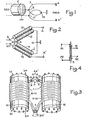
- FIG. 1 is a block diagram of a balun 1 (balun in the English literature) intended to allow the passage from the characteristic impedance of 50 ohms of a coaxial cable, 2, to a characteristic impedance of 200 ohms .
- the coaxial cable 2 whose external conductor is grounded constitutes a supply line asymmetrical with respect to ground and is connected, by its internal and external conductors, respectively to the terminals B and M 'of the primary circuit of the balun 1.
- the balun 1 is an autotransformer schematized by a conductor forming two turns, whose midpoint, M, is grounded and whose ends A and A 'constitute the terminals of the secondary circuit.
- the terminals B and M ' are respectively located in the middle of the two turns of the balun.
- the winding of the balun 1 is constituted by the inner conductors of cables 10, 11, 12 and 13 connected in series in this order.
- FIG. 3 An embodiment of the transformer according to FIGS. 1 and 2 is given in FIG. 3.
- This figure shows that the joined cables 10-12 and 11-13 are placed under the same plastic sheath and are wound respectively on two hollow coils 14 and 15 made up each by a cylinder closed at each of its ends by a cover pierced with eight holes.
- These coils are made of polytetrafluoroethylene (better known under the trademark Teflon) and have a length of 250 mm for a diameter of 150 mm.
- Teflon polytetrafluoroethylene
- the adjoining cables 10-12 and 11-13 are wound to form substantially eight turns around their coil. As it follows from what has been indicated above, the number of turns has been chosen as large as possible to allow operation at relatively low frequencies while also allowing operation at 30 MHz.
- Eight ferrite bars are arranged in each of the coils 14 and 15, parallel to the major axis not shown of these coils, passing through the holes drilled for this purpose in the end covers of the coils.
- These bars are cylindrical bars with a length of 300 mm and a diameter of 10 mm; they are marketed by the French company L. ⁇ .C - CICE which manufactures them in a ferrite powder whose reference is H30. Thanks to these ferrite bars which constitute, for each coil, an open type magnetic circuit, the characteristics of the balun are improved at low frequencies so as to cover a frequency band up to 2 MHz.
- connection K produced by metal wire, between the external conductors of the cables 10-12 and 11 -13.
- the coaxial cable is a cable whose inner conductor, insulation and outer conductor have a diameter of 2 mm, 7, respectively. 8 mm and 8 mm.
- the balun thus produced is designed for a normal operating power of 10 kW.
- the block diagram according to FIG. 4 relates to another example of a transformer according to the invention.
- This transformer, 3, is an autotransformer which comprises, between the terminals P1 P2 of its primary circuit, 13 turns and, between the terminals SI, S2 of its secondary circuit, 16 turns, that is to say the 13 common turns with the primary circuit and, on either side of these 13 turns, one and a half turns; these two times a turn and a half are, as shown in Figure 4, wound not in the extension of the 13 turns but over the 13 turns in order to be crossed by the maximum of the field created by the primary circuit; in fact, in the embodiment of this autotransformer, as in the embodiment according to FIG.
- the magnetic circuit is an open magnetic circuit, formed of eight ferrite bars and these bars are identical to those described with the help of FIG. 3
- the single coil used to support the turns and the bars is a coil similar to that of the balun of FIG. 3 but with a length reduced to 160 mm, which means that the ferrite bars exceed 70 mm on either side. of the coil.
- a notch three millimeters deep, traced helically on the coil with a pitch equal to 5 mm, is used to maintain the 13 turns of the primary circuit; these turns consist of a bare wire 3 mm in diameter.
- the two and a half turns relating to the secondary circuit of the autotransformer they are made of insulated wire whose diameter of the conductor is 2 mm; these turns are wound on eight insulating bars, parallel to the long axis of the coil and regularly arranged around the coil to which they are fixed by screws; notches in the insulating bars determine the position of the two and a half turns.
- the autotransformer, 3, which has just been described with the aid of FIG. 4 operates in the frequency band going from 2 to 30 MHz with a normal power of use of 10 kW and is intended to allow the passage of '' an impedance of 200 ohms to an impedance of 300 ohms.
- the present invention is not limited to the examples described; it applies to both autotransformers and transformers with separate primary and secondary circuits; it also applies to the case where the number of ferrite bars of the magnetic circuit is different from eight and in particular to the case where this number is reduced to 2, it being understood that, as regards the problem of the dissipation of calories , it is preferable, for an equal volume of ferrite, to take several bars.
- the invention applies, in particular, to the production of all transmission transformers for HF telecommunications unless space or weight problems arise, but this is rarely the case. It should also be noted that the transformers according to the invention can be cooled by forced air, which obviously allows, at equal power, to reduce their weight and their volume.
Landscapes
- Engineering & Computer Science (AREA)
- Power Engineering (AREA)
- Multimedia (AREA)
- Coils Or Transformers For Communication (AREA)
Applications Claiming Priority (2)
| Application Number | Priority Date | Filing Date | Title |
|---|---|---|---|
| FR8218237 | 1982-10-29 | ||
| FR8218237A FR2535515A1 (fr) | 1982-10-29 | 1982-10-29 | Transformateur d'emission, a large bande, pour telecommunications h.f. |
Publications (1)
| Publication Number | Publication Date |
|---|---|
| EP0108010A1 true EP0108010A1 (fr) | 1984-05-09 |
Family
ID=9278767
Family Applications (1)
| Application Number | Title | Priority Date | Filing Date |
|---|---|---|---|
| EP83402040A Withdrawn EP0108010A1 (fr) | 1982-10-29 | 1983-10-21 | Transformateur d'émission, à large bande, pour télécommunications H.F. |
Country Status (3)
| Country | Link |
|---|---|
| EP (1) | EP0108010A1 (OSRAM) |
| FR (1) | FR2535515A1 (OSRAM) |
| IT (1) | IT8321668V0 (OSRAM) |
Cited By (1)
| Publication number | Priority date | Publication date | Assignee | Title |
|---|---|---|---|---|
| EP0399975A3 (en) * | 1989-05-22 | 1991-04-17 | Nokia Mobile Phones Ltd. | Rf connector for the connection of a radiotelephone to an external antenna |
Citations (3)
| Publication number | Priority date | Publication date | Assignee | Title |
|---|---|---|---|---|
| FR1231183A (fr) * | 1959-04-09 | 1960-09-27 | Thomson Houston Comp Francaise | Perfectionnements aux réseaux radioélectriques transformateurs d'impédance |
| DE1207980B (de) * | 1960-01-15 | 1965-12-30 | Amalgamated Wireless Australas | Hochfrequenz-Kopplungstransformator |
| DE1516030A1 (de) * | 1966-01-03 | 1969-10-23 | Telefunken Patent | Breitbanduebertrager |
-
1982
- 1982-10-29 FR FR8218237A patent/FR2535515A1/fr active Granted
-
1983
- 1983-04-28 IT IT2166883U patent/IT8321668V0/it unknown
- 1983-10-21 EP EP83402040A patent/EP0108010A1/fr not_active Withdrawn
Patent Citations (3)
| Publication number | Priority date | Publication date | Assignee | Title |
|---|---|---|---|---|
| FR1231183A (fr) * | 1959-04-09 | 1960-09-27 | Thomson Houston Comp Francaise | Perfectionnements aux réseaux radioélectriques transformateurs d'impédance |
| DE1207980B (de) * | 1960-01-15 | 1965-12-30 | Amalgamated Wireless Australas | Hochfrequenz-Kopplungstransformator |
| DE1516030A1 (de) * | 1966-01-03 | 1969-10-23 | Telefunken Patent | Breitbanduebertrager |
Cited By (1)
| Publication number | Priority date | Publication date | Assignee | Title |
|---|---|---|---|---|
| EP0399975A3 (en) * | 1989-05-22 | 1991-04-17 | Nokia Mobile Phones Ltd. | Rf connector for the connection of a radiotelephone to an external antenna |
Also Published As
| Publication number | Publication date |
|---|---|
| FR2535515B1 (OSRAM) | 1985-02-01 |
| FR2535515A1 (fr) | 1984-05-04 |
| IT8321668V0 (it) | 1983-04-28 |
Similar Documents
| Publication | Publication Date | Title |
|---|---|---|
| FR2701156A1 (fr) | Conducteur isolé, dispositif à bobine électrique comportant un tel conducteur et méthode d'optimisation mettant en Óoeuvre un tel conducteur. | |
| US6750752B2 (en) | High power wideband balun and power combiner/divider incorporating such a balun | |
| EP0523588B1 (fr) | Bobinage de transformateur constitué d'un ruban isolant comportant des motifs électriquement conducteurs permettant de réaliser une mise en parallèle des motifs lors du pliage en accordéon de ce ruban | |
| EP0129464B1 (fr) | Transformateur d'impédance, à large bande, de rapport de transformation voisin de trois, pour radiofréquences | |
| FR2597266A1 (fr) | Antenne a large bande | |
| CA2294109C (fr) | Procede de bobinage en deux plans d'encoche pour une machine electrique tournante | |
| EP0108010A1 (fr) | Transformateur d'émission, à large bande, pour télécommunications H.F. | |
| US3783415A (en) | Transformer | |
| CA2240768C (en) | Triple core toroidal transformer | |
| FR2525022A1 (fr) | Transformateur a basse frequence | |
| JP2001503201A (ja) | インダクタ | |
| JP6724887B2 (ja) | バルントランスおよびその製造方法 | |
| EP0258362A1 (fr) | Transformateur haute tension | |
| FR3073972A1 (fr) | Procede d'assemblage d'un inducteur magnetique et inducteur magnetique susceptible d'etre obtenu avec un tel procede | |
| EP0420337A1 (fr) | Mélangeur hyperfréquence équilibré à circuit "balun" | |
| CA2031076A1 (fr) | Filtre eliminateur de bande pour guide d'ondes hyperfrequences | |
| JP7005113B2 (ja) | 同軸避雷器 | |
| FR2823365A1 (fr) | Enroulement electrique, son procede de realisation et composant electromagnetique integrant au moins un tel enroulement | |
| FR3103625A1 (fr) | Bobinage, procédé de réalisation correspondant et aéronef comportant un tel bobinage | |
| FR2656951A1 (fr) | Transformateur de type torique. | |
| GB1417093A (en) | Balun transformers | |
| CN116206888A (zh) | 一种用于高速高频连接器的线圈绕线方法及结构 | |
| FR2526232A1 (fr) | Perfectionnements apportes aux cavites resonnantes du type lignes de transmission | |
| JP6930403B2 (ja) | バルントランスおよびその製造方法 | |
| JP2024175719A (ja) | 高周波バラン |
Legal Events
| Date | Code | Title | Description |
|---|---|---|---|
| PUAI | Public reference made under article 153(3) epc to a published international application that has entered the european phase |
Free format text: ORIGINAL CODE: 0009012 |
|
| AK | Designated contracting states |
Designated state(s): CH DE GB LI NL |
|
| 17P | Request for examination filed |
Effective date: 19840922 |
|
| STAA | Information on the status of an ep patent application or granted ep patent |
Free format text: STATUS: THE APPLICATION IS DEEMED TO BE WITHDRAWN |
|
| 18D | Application deemed to be withdrawn |
Effective date: 19860301 |
|
| RIN1 | Information on inventor provided before grant (corrected) |
Inventor name: LEFEBVRE-ALBARET, CLAUDE |