EP0107791A1 - Méthode de fabrication des dérivations de guides d'ondes lumineuses et des multi-démultiplexeurs à l'aide du principe de séparation des rayons lumineux - Google Patents
Méthode de fabrication des dérivations de guides d'ondes lumineuses et des multi-démultiplexeurs à l'aide du principe de séparation des rayons lumineux Download PDFInfo
- Publication number
- EP0107791A1 EP0107791A1 EP83109570A EP83109570A EP0107791A1 EP 0107791 A1 EP0107791 A1 EP 0107791A1 EP 83109570 A EP83109570 A EP 83109570A EP 83109570 A EP83109570 A EP 83109570A EP 0107791 A1 EP0107791 A1 EP 0107791A1
- Authority
- EP
- European Patent Office
- Prior art keywords
- filter
- mirror
- parallel
- optical fibers
- optical
- Prior art date
- Legal status (The legal status is an assumption and is not a legal conclusion. Google has not performed a legal analysis and makes no representation as to the accuracy of the status listed.)
- Granted
Links
Images

Classifications
-
- G—PHYSICS
- G02—OPTICS
- G02B—OPTICAL ELEMENTS, SYSTEMS OR APPARATUS
- G02B6/00—Light guides; Structural details of arrangements comprising light guides and other optical elements, e.g. couplings
- G02B6/24—Coupling light guides
- G02B6/26—Optical coupling means
- G02B6/28—Optical coupling means having data bus means, i.e. plural waveguides interconnected and providing an inherently bidirectional system by mixing and splitting signals
- G02B6/293—Optical coupling means having data bus means, i.e. plural waveguides interconnected and providing an inherently bidirectional system by mixing and splitting signals with wavelength selective means
- G02B6/29379—Optical coupling means having data bus means, i.e. plural waveguides interconnected and providing an inherently bidirectional system by mixing and splitting signals with wavelength selective means characterised by the function or use of the complete device
- G02B6/2938—Optical coupling means having data bus means, i.e. plural waveguides interconnected and providing an inherently bidirectional system by mixing and splitting signals with wavelength selective means characterised by the function or use of the complete device for multiplexing or demultiplexing, i.e. combining or separating wavelengths, e.g. 1xN, NxM
-
- G—PHYSICS
- G02—OPTICS
- G02B—OPTICAL ELEMENTS, SYSTEMS OR APPARATUS
- G02B6/00—Light guides; Structural details of arrangements comprising light guides and other optical elements, e.g. couplings
- G02B6/24—Coupling light guides
- G02B6/26—Optical coupling means
- G02B6/28—Optical coupling means having data bus means, i.e. plural waveguides interconnected and providing an inherently bidirectional system by mixing and splitting signals
- G02B6/293—Optical coupling means having data bus means, i.e. plural waveguides interconnected and providing an inherently bidirectional system by mixing and splitting signals with wavelength selective means
- G02B6/29346—Optical coupling means having data bus means, i.e. plural waveguides interconnected and providing an inherently bidirectional system by mixing and splitting signals with wavelength selective means operating by wave or beam interference
- G02B6/29361—Interference filters, e.g. multilayer coatings, thin film filters, dichroic splitters or mirrors based on multilayers, WDM filters
- G02B6/29368—Light guide comprising the filter, e.g. filter deposited on a fibre end
-
- Y—GENERAL TAGGING OF NEW TECHNOLOGICAL DEVELOPMENTS; GENERAL TAGGING OF CROSS-SECTIONAL TECHNOLOGIES SPANNING OVER SEVERAL SECTIONS OF THE IPC; TECHNICAL SUBJECTS COVERED BY FORMER USPC CROSS-REFERENCE ART COLLECTIONS [XRACs] AND DIGESTS
- Y10—TECHNICAL SUBJECTS COVERED BY FORMER USPC
- Y10T—TECHNICAL SUBJECTS COVERED BY FORMER US CLASSIFICATION
- Y10T29/00—Metal working
- Y10T29/49—Method of mechanical manufacture
- Y10T29/49799—Providing transitory integral holding or handling portion
Definitions
- the present invention relates to a method for the production of optical waveguides and multi / demultiplexers according to the beam splitter principle according to the preamble of claim 1.
- the body connection step is carried out first by adjusting the body and the further body relative to one another and cementing them together. Then the process step for the production of the body is carried out with a filter or mirror, a separation at an angle of 45 ° or 70 ° to the fiber axes being carried out.
- the separating surface on the separating part which also has the optical waveguide of the further body, must be ground very carefully to such an extent that after connecting the separating parts, the light reflected by the filter or mirror from an optical waveguide of one body by the assigned optical waveguide of the further body can be detected. This step is time-consuming and critical with regard to the yield of branching elements.
- the object of the invention is therefore to improve the method of the type mentioned in that the time-consuming and critical in terms of yield There is no need to grind one parting surface.
- the adjustment effort in the body connection step can be greatly reduced if, according to claim 2, bodies are used with reference surfaces which can be placed on a stop surface in the body connection step and are parallel to the planes spanned by the paired optical waveguides. As a result, the entire adjustment can be reduced to a linear displacement in the direction of the severed optical fiber axes, which can also be controlled by means of microprocessors.
- a body is preferably produced in accordance with claim 3.
- Base bodies which are preferably used for the bodies are specified in claim 8.
- the wavelength-selective filter or the partially transparent mirror is usually applied by vapor deposition. Difficulties arise in the manufacture of branches and multi- or demultiplexers with fiber tails because the fiber tails interfere with the recipient. To avoid these difficulties, the procedure can be as set out in claim 9. Due to the double severing, a fiber-tail-free separating part with a polished separating surface to be steamed can be obtained, which can be steamed without interference in the recipient. Additional coupling losses have to be accepted with this method, but these are low.
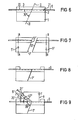
- FIGS. 6 to 9 show individual process steps of a process for producing an optical waveguide branch or multiplexer / demultiplexer with fiber tails using the example of a multiplexer / demultiplexer with a 70 "filter.
- Figures 1 and 2 show in a side or fragmentary end view the one body used in the manufacture of the branch or multi / demultiplexer with 45 ° mirror or filter.
- This has a base body, which consists of a support body 1, for example made of quartz glass, to which a silicon plate 2 is glued.
- a plurality of equidistant, V-shaped grooves 21 have been produced in the silicon wafer 2 by anisotropic etching, which grooves run parallel according to FIGS. 1 to 5 and are arranged in the flat side surface 20 of the silicon wafer facing away from the support body 1.
- Optical waveguides 4 in the form of glass fibers, in particular core-cladding glass fibers, are cemented into these grooves 21 with the aid of a glass cover plate 3.
- the body according to FIGS. 1 and 2 is severed vertically to the plane of the drawing along the section line I - I drawn in FIG. 1 and enclosing an angle of 45 ° with the fiber axes, and the separation Surfaces 51 and 61 ground and optically polished on the resulting separating parts shown in FIG. 3.
- the cut can expediently also be made at an angle of, for example, 70 ° to the fiber axes.
- a partially transparent mirror layer or filter layer is vapor-deposited, which must be wavelength-selective in multi / demultiplexers. This layer is designated by 7 in FIG.
- the cover plate 3 is ground off from the body with filter or mirror shown in FIG. To reduce reflection losses, part of the fiber cladding of the fibers 4 can also be ground off if necessary.
- the further body can basically be constructed in the same way as the one body according to FIGS. 1 and 2. That is, it can consist of a base body, for example a support body 1 ', onto which a silicon plate 2' is glued, in the free surface of which by anisotropy Etching several equidistant V-shaped grooves 21 'have been produced, in which optical fibers 4' are cemented with the aid of a cover body 3 '. But it is important that the optical waveguides 4 ′ end in a side surface 81 of the further body 8, ie this surface 81 has fiber end faces. This surface 81 is ground and polished together with the fiber end faces.
- the further body 8 is placed with its end face 81 on the ground surface 82 of the body with the filter or mirror 7 and then the two bodies are adjusted to one another so that the light coupled out of a fiber 4 on the filter or mirror 7 into the its associated fiber 4 'of the further body 8 is coupled.
- the two bodies are cemented to one another, so that the branch or multi- / demultiplexer shown in FIG. 5 has arisen.
- the assembled body according to FIG. 5 can be sawn into individual branches or multi / demultiplexers parallel to a plane spanned by a fiber 4 and the fiber 4 ′ assigned to it.
- glass bodies or other plastically deformable bodies can also be used as the base body, into which V-shaped grooves are scored, sawn, pressed or embossed.
- FIG. 6 shows in the same side view as in FIG. 1 the one body used in this production, which is identical to the carrier body according to FIGS. 1 and 2 except for the fiber tails projecting beyond the body on both sides.
- the fibers projecting beyond a body are designated 9 and 9 'in FIGS. 6 to 9.
- the body according to FIG. 1 is severed along the section line II-II enclosing an angle of 70 ° with the fiber axes, vertical to the plane of the drawing, so that the two separating parts 5 ', 6' shown in FIG. 7 with the separating surfaces 51 'and 61' are produced .
- a frequency-selective filter layer 7 ' is evaporated onto one of the two ground and polished separating surfaces, for example the separating surface 51', and then the two separating parts 5 'and 6' are reassembled and connected to one another in such a way that a body identical to that of FIG filter layer is created.
- the one body can first be cut along the section line A - A or B - B at an angle of 70 ° or 45 ° before cutting. After vapor deposition, all three or four parts of the body have to be adjusted to each other again. If the body is cut both along the section line A - A and the section line B - B, the structure of the taps or multi- / demultiplexers can be carried out as in the method according to FIGS. 1 to 5, by initially only using the one between the Cut lines A - A and B - B lying middle section of the body worked becomes. Only when a composite body corresponding to FIG.
- the cover plate 3 of the body formed in both cases with a filter or mirror and at least one additional construction joint is ground down to put on the further body 8.
- a complete grinding of the cover plate 3 must be avoided here because of the risk of breaking the protruding fibers.
- the cover plate 3 is therefore only removed in a central section of the body in which the further body is to be placed. In end sections of one body, remnants of the small plate remain, so that the body shown in FIG. 8 is formed. In the middle section, a part of the jacket of the fibers can also be removed if necessary.
- the removal of the cover plate 3 and possibly the fiber sheaths in some areas can be accomplished, for example, with a fine-grained diamond disc.
- Figure 9 shows the finished end product after the body joining step.
- the fibers 9 'of the further body 8 of the end product branch off in accordance with the law of reflection and the 70 ° angle between the fibers 9 and the filter 7' at an angle of 40 ° to the fibers 9.
Landscapes
- Physics & Mathematics (AREA)
- General Physics & Mathematics (AREA)
- Optics & Photonics (AREA)
- Optical Integrated Circuits (AREA)
- Optical Couplings Of Light Guides (AREA)
Applications Claiming Priority (2)
| Application Number | Priority Date | Filing Date | Title |
|---|---|---|---|
| DE3236149 | 1982-09-29 | ||
| DE19823236149 DE3236149A1 (de) | 1982-09-29 | 1982-09-29 | Verfahren zur herstellung von lichtwellenleiter-abzweigern und -multi-/demultiplexern nach dem strahlteilerprinzip |
Publications (2)
| Publication Number | Publication Date |
|---|---|
| EP0107791A1 true EP0107791A1 (fr) | 1984-05-09 |
| EP0107791B1 EP0107791B1 (fr) | 1987-12-16 |
Family
ID=6174520
Family Applications (1)
| Application Number | Title | Priority Date | Filing Date |
|---|---|---|---|
| EP83109570A Expired EP0107791B1 (fr) | 1982-09-29 | 1983-09-26 | Méthode de fabrication des dérivations de guides d'ondes lumineuses et des multi-démultiplexeurs à l'aide du principe de séparation des rayons lumineux |
Country Status (4)
| Country | Link |
|---|---|
| US (1) | US4541159A (fr) |
| EP (1) | EP0107791B1 (fr) |
| JP (1) | JPS5983109A (fr) |
| DE (2) | DE3236149A1 (fr) |
Cited By (2)
| Publication number | Priority date | Publication date | Assignee | Title |
|---|---|---|---|---|
| EP0292331A2 (fr) * | 1987-05-22 | 1988-11-23 | The Furukawa Electric Co., Ltd. | Elément à fibres optiques multiples et son procédé de fabrication |
| EP0646812A1 (fr) * | 1993-10-01 | 1995-04-05 | Nippon Hoso Kyokai | Coupleur optique avec des surfaces terminales inclinées |
Families Citing this family (9)
| Publication number | Priority date | Publication date | Assignee | Title |
|---|---|---|---|---|
| EP0204980A1 (fr) * | 1985-06-03 | 1986-12-17 | Siemens Aktiengesellschaft | Méthode de fabrication d'un connecteur pour des guides d'ondes optiques comportant trois portes ou plus utilisant le principe de division du faisceau |
| EP0234280A1 (fr) * | 1986-01-31 | 1987-09-02 | Siemens Aktiengesellschaft | Commutateur de lumière pour un système de communication avec trois raccordements de lumière |
| FR2608785B1 (fr) * | 1986-12-19 | 1989-08-04 | Thomson Csf | Dispositif de connexion de fibres optiques a un circuit optique integre et procede de realisation |
| JPH0284601A (ja) * | 1988-06-29 | 1990-03-26 | Furukawa Electric Co Ltd:The | 光部品とその製造方法 |
| JPH0321905A (ja) * | 1989-06-19 | 1991-01-30 | Fujitsu Ltd | 偏波カプラ |
| GB9203128D0 (en) * | 1992-02-14 | 1992-04-01 | Lucas Ind Plc | Alignment device for optical fibre |
| US5562657A (en) * | 1994-09-19 | 1996-10-08 | Griffin; Stephen E. | Side fire laser catheter method and apparatus |
| US6819871B1 (en) * | 2001-03-16 | 2004-11-16 | 4 Wave, Inc. | Multi-channel optical filter and multiplexer formed from stacks of thin-film layers |
| WO2013176135A1 (fr) * | 2012-05-22 | 2013-11-28 | 日本電気株式会社 | Convertisseur de chemin optique et procédé de fabrication dudit convertisseur |
Citations (4)
| Publication number | Priority date | Publication date | Assignee | Title |
|---|---|---|---|---|
| EP0012188A1 (fr) * | 1978-11-29 | 1980-06-25 | Siemens Aktiengesellschaft | Procédé pour la fabrication d'un séparateur à fibre-optique |
| EP0026379A1 (fr) * | 1979-09-25 | 1981-04-08 | Siemens Aktiengesellschaft | Dispositif pour coupler latéralement la lumière dans un guide d'ondes optiques en fibre de verre |
| EP0037057A1 (fr) * | 1980-03-28 | 1981-10-07 | Siemens Aktiengesellschaft | Branchement de guides d'ondes optiquesà faibles effets de polarisation |
| GB2072876A (en) * | 1980-04-02 | 1981-10-07 | Int Standard Electric Corp | Bidirectional coupler for communication over a single fibre |
Family Cites Families (7)
| Publication number | Priority date | Publication date | Assignee | Title |
|---|---|---|---|---|
| US3820396A (en) * | 1971-04-22 | 1974-06-28 | A Gamer | Fluid signal indicator |
| DE2851667A1 (de) * | 1978-11-29 | 1980-07-10 | Siemens Ag | Abzweigelement fuer monomode-lichtwellenleiter und verfahren zu seiner herstellung |
| DE2920957C2 (de) * | 1979-05-23 | 1984-08-23 | Siemens AG, 1000 Berlin und 8000 München | Verfahren zur Herstellung eines Verzweigerelements |
| DE3008106A1 (de) * | 1980-03-03 | 1981-09-10 | Siemens AG, 1000 Berlin und 8000 München | Vielfach-verzweigerelement |
| DE3008029A1 (de) * | 1980-03-03 | 1981-09-10 | Siemens AG, 1000 Berlin und 8000 München | Optischer baustein fuer multiplexer/demultiplexer |
| US4336047A (en) * | 1981-01-02 | 1982-06-22 | The United States Of America As Represented By The Secretary Of The Navy | Method for fabricating single-mode and multimode fiber optic access couplers |
| DE3112801A1 (de) * | 1981-03-31 | 1982-10-14 | Siemens AG, 1000 Berlin und 8000 München | Verfahren zur herstellung von faserverzweigern nach dem strahlteilerprinzip |
-
1982
- 1982-09-29 DE DE19823236149 patent/DE3236149A1/de not_active Withdrawn
-
1983
- 1983-07-08 US US06/511,840 patent/US4541159A/en not_active Expired - Fee Related
- 1983-09-26 DE DE8383109570T patent/DE3374963D1/de not_active Expired
- 1983-09-26 EP EP83109570A patent/EP0107791B1/fr not_active Expired
- 1983-09-28 JP JP58180067A patent/JPS5983109A/ja active Pending
Patent Citations (4)
| Publication number | Priority date | Publication date | Assignee | Title |
|---|---|---|---|---|
| EP0012188A1 (fr) * | 1978-11-29 | 1980-06-25 | Siemens Aktiengesellschaft | Procédé pour la fabrication d'un séparateur à fibre-optique |
| EP0026379A1 (fr) * | 1979-09-25 | 1981-04-08 | Siemens Aktiengesellschaft | Dispositif pour coupler latéralement la lumière dans un guide d'ondes optiques en fibre de verre |
| EP0037057A1 (fr) * | 1980-03-28 | 1981-10-07 | Siemens Aktiengesellschaft | Branchement de guides d'ondes optiquesà faibles effets de polarisation |
| GB2072876A (en) * | 1980-04-02 | 1981-10-07 | Int Standard Electric Corp | Bidirectional coupler for communication over a single fibre |
Cited By (5)
| Publication number | Priority date | Publication date | Assignee | Title |
|---|---|---|---|---|
| EP0292331A2 (fr) * | 1987-05-22 | 1988-11-23 | The Furukawa Electric Co., Ltd. | Elément à fibres optiques multiples et son procédé de fabrication |
| EP0292331A3 (en) * | 1987-05-22 | 1989-07-12 | The Furukawa Electric Co., Ltd. | Multiple-fiber optical component and method for manufacturing the same |
| US4900118A (en) * | 1987-05-22 | 1990-02-13 | Furukawa Electric Co., Ltd. | Multiple-fiber optical component and method for manufacturing of the same |
| EP0646812A1 (fr) * | 1993-10-01 | 1995-04-05 | Nippon Hoso Kyokai | Coupleur optique avec des surfaces terminales inclinées |
| US5497438A (en) * | 1993-10-01 | 1996-03-05 | Nippon Hoso Kyokai | Optical transmission and reception module having coupled optical waveguide chips |
Also Published As
| Publication number | Publication date |
|---|---|
| JPS5983109A (ja) | 1984-05-14 |
| DE3236149A1 (de) | 1984-03-29 |
| EP0107791B1 (fr) | 1987-12-16 |
| DE3374963D1 (en) | 1988-01-28 |
| US4541159A (en) | 1985-09-17 |
Similar Documents
| Publication | Publication Date | Title |
|---|---|---|
| EP0037057B1 (fr) | Branchement de guides d'ondes optiquesà faibles effets de polarisation | |
| DE69924051T2 (de) | Faseroptischer Wellenlängenfilter und Verfahren zu dessen Herstellung | |
| DE2910291A1 (de) | Bauelement mit optischen lichtwellenleitern | |
| DE3413703A1 (de) | Optischer multiplexer/demultiplexer | |
| DE3038048A1 (de) | Faseroptische richtungs-kopplungseinrichrung und verfahren zu deren herstellung | |
| EP0723670B9 (fr) | Procede de fabrication de prismes, notamment de microprismes et de separateurs de rayonnement | |
| DE2840493A1 (de) | Frequenzselektives optisches lichtverteilerelement und verfahren zu seiner herstellung | |
| DE3920416A1 (de) | Optisches bauteil, und verfahren zu seiner herstellung | |
| EP0631159A1 (fr) | Couplage entre un guide d'ondes optique planaire et une fibre optique de fabrication d'un guide d'ondes approprié | |
| EP0012188B1 (fr) | Procédé pour la fabrication d'un séparateur à fibre-optique | |
| EP0107791A1 (fr) | Méthode de fabrication des dérivations de guides d'ondes lumineuses et des multi-démultiplexeurs à l'aide du principe de séparation des rayons lumineux | |
| DE2851625C2 (fr) | ||
| DE2920957A1 (de) | Verzweigerelement und verfahren zu seiner herstellung | |
| EP0204980A1 (fr) | Méthode de fabrication d'un connecteur pour des guides d'ondes optiques comportant trois portes ou plus utilisant le principe de division du faisceau | |
| EP0388642A2 (fr) | Elément micromécanique | |
| EP0012901B1 (fr) | Procédé de fabrication de coupleurs de guides d'ondes optiques | |
| DE3801764A1 (de) | Wellenlaengenmultiplexer oder -demultiplexer, sowie verfahren zur herstellung des wellenlaengenmultiplexers oder -demultiplexers | |
| EP0090999B1 (fr) | Procédé pour la fabrication d'un corps présentant un agencement de guides d'ondes optiques | |
| EP0123865A2 (fr) | Branchement de guides d'ondes lumineuses, son application et procédé de fabrication | |
| DE2851654C2 (fr) | ||
| EP0576999A1 (fr) | Méthode et dispositif pour produire des éléments optiques | |
| DE2930454A1 (de) | Verfahren zur herstellung von lichtleiter-richtkopplern | |
| DE3402258A1 (de) | Farbenzerlegendes bauelement | |
| DE3413704A1 (de) | Optischer leistungsteiler | |
| DE2942664A1 (de) | Verfahren zur herstellung eines optischen strahlteilers |
Legal Events
| Date | Code | Title | Description |
|---|---|---|---|
| PUAI | Public reference made under article 153(3) epc to a published international application that has entered the european phase |
Free format text: ORIGINAL CODE: 0009012 |
|
| AK | Designated contracting states |
Designated state(s): DE FR GB |
|
| 17P | Request for examination filed |
Effective date: 19841109 |
|
| 17Q | First examination report despatched |
Effective date: 19860613 |
|
| GRAA | (expected) grant |
Free format text: ORIGINAL CODE: 0009210 |
|
| AK | Designated contracting states |
Kind code of ref document: B1 Designated state(s): DE FR GB |
|
| REF | Corresponds to: |
Ref document number: 3374963 Country of ref document: DE Date of ref document: 19880128 |
|
| ET | Fr: translation filed | ||
| GBT | Gb: translation of ep patent filed (gb section 77(6)(a)/1977) | ||
| PLBE | No opposition filed within time limit |
Free format text: ORIGINAL CODE: 0009261 |
|
| STAA | Information on the status of an ep patent application or granted ep patent |
Free format text: STATUS: NO OPPOSITION FILED WITHIN TIME LIMIT |
|
| 26N | No opposition filed | ||
| PG25 | Lapsed in a contracting state [announced via postgrant information from national office to epo] |
Ref country code: GB Effective date: 19890926 |
|
| GBPC | Gb: european patent ceased through non-payment of renewal fee | ||
| PG25 | Lapsed in a contracting state [announced via postgrant information from national office to epo] |
Ref country code: FR Effective date: 19900531 |
|
| PG25 | Lapsed in a contracting state [announced via postgrant information from national office to epo] |
Ref country code: DE Effective date: 19900601 |
|
| REG | Reference to a national code |
Ref country code: FR Ref legal event code: ST |