EP0107752B1 - Process and device for producing variable grain size materials from mixtures - Google Patents
Process and device for producing variable grain size materials from mixtures Download PDFInfo
- Publication number
- EP0107752B1 EP0107752B1 EP83106667A EP83106667A EP0107752B1 EP 0107752 B1 EP0107752 B1 EP 0107752B1 EP 83106667 A EP83106667 A EP 83106667A EP 83106667 A EP83106667 A EP 83106667A EP 0107752 B1 EP0107752 B1 EP 0107752B1
- Authority
- EP
- European Patent Office
- Prior art keywords
- container
- coarse
- fine
- spiral
- screen
- Prior art date
- Legal status (The legal status is an assumption and is not a legal conclusion. Google has not performed a legal analysis and makes no representation as to the accuracy of the status listed.)
- Expired
Links
Images

Classifications
-
- B—PERFORMING OPERATIONS; TRANSPORTING
- B07—SEPARATING SOLIDS FROM SOLIDS; SORTING
- B07B—SEPARATING SOLIDS FROM SOLIDS BY SIEVING, SCREENING, SIFTING OR BY USING GAS CURRENTS; SEPARATING BY OTHER DRY METHODS APPLICABLE TO BULK MATERIAL, e.g. LOOSE ARTICLES FIT TO BE HANDLED LIKE BULK MATERIAL
- B07B13/00—Grading or sorting solid materials by dry methods, not otherwise provided for; Sorting articles otherwise than by indirectly controlled devices
- B07B13/14—Details or accessories
- B07B13/16—Feed or discharge arrangements
-
- B—PERFORMING OPERATIONS; TRANSPORTING
- B22—CASTING; POWDER METALLURGY
- B22C—FOUNDRY MOULDING
- B22C5/00—Machines or devices specially designed for dressing or handling the mould material so far as specially adapted for that purpose
- B22C5/06—Machines or devices specially designed for dressing or handling the mould material so far as specially adapted for that purpose by sieving or magnetic separating
Definitions
- the invention relates to a method and a device for processing foundry sand, in particular from hot, previously used foundry material mixtures bonded with synthetic resin and reinforced with metal parts, which vibrates on increasing surfaces, is crushed and from a higher entrance area, in the direction of the Bottom of a container and then is conveyed against its gravity to a higher-lying exit area, the foundry sand first being crushed in the interior of the container, sifted and / or coarsely screened in order to achieve fine grain, oversize grain and waste product, and then the falling material is finely screened and the fine grain is removed is withdrawn from the cycle.
- a method of this type and an apparatus for carrying out this method are known from DE-A-30 21 490.
- a rotationally symmetrical break pot is disclosed, the outer surface of which is designed as a sieve wall for coarse screening of the foundry sand.
- Behind the screen wall is a housing ring space, which is delimited by a cylindrical outer wall.
- two helical surfaces with a rectangular cross-section are arranged one above the other at a distance.
- the upper spiral surface consists of sections or a total of slotted sieves, whereas the lower spiral bottom is closed.
- the coarsely screened oversize remaining on the upper spiral surface is extracted from the process in a second discharge, likewise arranged in the upper region of the break pot.
- the waste product retained by the cylindrical sieve wall of the crushing pot is discharged discontinuously from the lowerable container bottom via a chute.
- the foundry sand reaches after a coarse screening at the bottom of a container through a passage opening in a wall on a rising surface, above which bumpers are arranged at regular intervals to one another and to the inclined surface.
- the container, the rising surface and the bumpers are vibrated together by a vibration exciter.
- the mixture of substances climbs up the ascending surface, whereby the bump rods, which have the shape of a comb, are crushed, circulated and finally pressed in uncontrollable grain size over the exit area at the end of the ascending surface and fed to a device connected for further treatment.
- this method In addition to a great expenditure on equipment, this method also requires a considerable amount of space, which can amount to a depth of 5 m and a length of 10 m and more from the zero level near the upper edge of the container. In order to process the foundry sand using this method, several drives which are to be operated independently of one another and correspondingly high operating costs are also required.
- the invention is based on the object Preparation process and an apparatus for carrying out this process of the type mentioned at the outset, which ensures the high efficiency of continuously operated comminution and separation of foundry sand into the finished product, intermediate product and waste product and, due to strong friction, impact and impact forces, almost complete recovery of the fine grain fraction.
- This new functional principle can also not be achieved by transferring the principle of a scrubbing drum according to DE-A-29 07 727 to the subject matter of DE-AS 30 21 490, since its expansive drum wall, which is required for its circulating movement, does not conform to a device the DE-OS 30 21 490 can be used with a lowerable chute bottom for the waste product.
- DE-A-14 56 805 describes a device with a rotationally symmetrical, from above with crumbly or brittle goods, e.g. Waffles, biscuits or confectionery pieces are known to be loaded, which has in its interior a greenscreen extending over its cross-sectional area and inclined from the center towards the inner wall, and an inner helix surface rising from the edge of the coarse sieve to the inner wall of the container, which extends to the upper one Output area of the container forming edge leads.
- This device is only suitable for the separation of finished products and waste products and for further conveying the finished products out of the container.
- This device is not suitable for carrying out a recirculation process in the sense of the invention and does not suggest such a device, since it merely has the task of correctly feeding finished products which have already been filled in to a conveyor ramp which rises in a helical turn, only the finished products being dust and crumbs should be cleaned. A downsizing of substances with this device is undesirable and the preparation of an intermediate product from a mixture of substances of different grain sizes is not possible.
- DE-A-30 21 490 discussed at the outset of the state of the art in process engineering, there is a device with a coarse screen. a downstream fine sieve and a rising first outer spiral surface for the oversize grain attached to the outer wall of a rotationally symmetrical container, which reaches the first outer spiral surface through a first through opening in the container wall. Furthermore, this known device is provided with a discharge for the finished product with a second outer spiral surface arranged on the outer wall of the container.
- the problem underlying the invention is solved in terms of the device in that the coarse sieve in the interior of the container extends over its cross-sectional area and is inclined from the center towards the inner wall and an increasing from the edge of this coarse sieve on the inner wall of the container
- Their exit area from the container is provided with an internal spiral surface and that the fine sieve is arranged in the container below the coarse sieve, under which there is a second through opening for the finished product and that at the upper end of the first outer helical surface above the coarse sieve there is a third through opening to the interior of the Container is located.
- the fine screen is advantageously provided on its surface with a guide spiral in the form of a logarithmic spiral, the origin of which is arranged in the region below the central opening of the funnel and the end of which is guided approximately tangentially into the first through opening to the first outer spiral.
- this guide spiral Depending on the number of turns of this guide spiral, the sifted, coarsely screened material falling through the central opening of the funnel can be guided over a considerable distance on the fine screen be, whereby not only a screening, but also a crushing screening process.
- this arrangement desirably increases the throughput path of the recirculation process of the oversize in a compact arrangement before the oversize gets into the first passage opening to the first outer helix and from there through the third passage opening into the container space above the coarse screen.
- a closed base plate is arranged below the fine sieve in the container and at the edge of it there is a second through opening in the container wall, which is followed by the rising second outer helix surface attached to the outer wall of the container, which leads to an exit area for the fine grain is led.
- the first and second outer helix surfaces are designed as channels known per se, under the bottom surfaces of which cavities are arranged for heat transfer. Such channels suitable for heat transfer, for example for a cooling process, are known from DE-PS 10 80 927 both in a side-by-side arrangement and in a top-down arrangement.
- the inner helix surface consists of a flat steel, the surface of which is inclined at an angle of 5 ° to 10 ° towards the inner wall of the container. In terms of conveying technology, this inner helix surface is ultimately only suitable for the upward transport of waste products that are inaccessible to size reduction through screening and coarse screening.
- the inner helix surface also has the function of a comminution or refraction element.
- the width of the inner helix surface increases in the direction of its slope and it is provided on its free edge with tines that break the mixture of substances.
- strong comminution and refraction are achieved on the rough, abrasive teeth on the one hand and the protruding edges of the widening inner helix surface on the other hand during the circulation process.
- the waste products are cleaned shortly before leaving the container in that the inner helix surface near its exit area from the container is designed as a sieve and in front of it a locking flap which blocks the inner helix surface and can be actuated from the outside is arranged .
- the latter is designed as an abrasion plate with longitudinal slots running perpendicular to the conveying direction of the mixture of materials and / or sharp-edged ridges, knobs, crescent-shaped, sharp-edged notches similar to a grater or rasp.
- the container is covered above the exit area of the inner spiral surface and the first and second outer spiral surfaces by a perforated grate which is detachably connected to it.
- the new device 1 for performing the method according to the invention consists essentially of a cylindrical container 2, in which a coarse sieve 3, a funnel 4 with a central opening 5, a guide spiral 6, a fine sieve 7 and a final one Floor plate 8 are arranged.
- a tensioning device 10 for the fine sieve 7, which can be adjusted via the nuts 9, is detachably attached.
- an inner helical surface 11 which rises from the edge 3' of the coarse sieve 3 which is inclined from the center towards the inner wall 2 'to the upper edge forming the exit region 2 "of the container 2.
- a first outer helical surface 12 for receiving the mixture of substances with oversize grain, abbreviated oversize, retained by the fine sieve 7, and underneath a second outer helical surface 12 for accommodating the product with fine grain size, hereinafter referred to as fine grain, let through the fine sieve 7.
- the first outer spiral surface 12 conveys the oversize particles retained by the fine sieve 7 and guided by the guide spiral 6 to the first outlet opening 14 above the coarse sieve 3 through a third through opening 15 into the interior of the container 2 arises from the interior of the container 2 via the coarse sieve 3, the funnel 4 with the central opening 5 and from there via the fine sieve 7 and the guide spiral 6 and finally via the first outer spiral surface 12, a recirculation circuit for the oversize particles.
- a second through opening 16 is arranged in the container wall at the edge 8 'of the bottom plate 8.
- This second through opening 16 is followed by the second, rising outer helix surface 13 for the upward conveyance of the fine grain let through the fine sieve 7.
- This second outer helical surface 13 is provided on its base 13 'with a cavity 17 for the flow of a heat transfer medium.
- the fine grain picked up by the second outer helical surface 13 can be cooled on the way to the discharge 18, from there into a sifter 19 and finally via a, e.g. pneumatic conveyor 20 are conveyed in the direction of arrow 21 to a silo, not shown.
- the container 2 is arranged on a central base 22, to which two vibration exciters 24, spaced 90 'apart with their longitudinal axes 23, and a plurality of feet 27 having supports 26 which are elastic toward the bottom surface 25 are fastened.
- the vibration exciter 24 can be designed both electromagnetically, electrodynamically and as a resonance oscillator.
- the container 2 is covered above the inner spiral surface 11 and the first and second outer spiral surfaces 12, 13 by a perforated grate 28, which is detachably connected to it and is indicated by dash-dotted lines.
- the origin 6 ', the guide spiral 6 consisting of a sheet metal strip is arranged below the central opening 5 of the funnel 4, while the end 6 "of the guide spiral is approximately tangential in the first through opening 14 ends in the container 2, which in turn is connected to the first outer helical surface 12.
- the inner spiral surface 11 consists of a flat steel, the surface of which is inclined by an angle "A of 5" to 10 "to the inner wall 2 'of the container.
- the width B of the inner spiral surface 11 increases Towards its slope and is provided on its free round edge 11 'with abrasive tines 29.
- the latter is designed as a sieve 31 and in front of it a locking flap 32 which blocks the inner spiral surface 11 and can be actuated from the outside
- the inner spiral surface 11 and the first and second outer spiral surfaces 12, 13 are detachably fastened to the container 2 or are provided with detachable, not shown wear pads.
- the coarse screen 3 is designed as an abrasion plate, similar to a grater or rasp.
- the abrasion effect can be increased on the one hand by longitudinal slots 34 running perpendicular to the conveying direction in the direction of arrow 33 and / or with sharp-edged ridges or knobs 35 and / or with crescent-shaped, sharp-edged notches 36.
- any design of the coarse sieve 3 is suitable which increases the abrasion effect of the mixture of substances that is constantly circulated by the vibrations.
- the coarse sieve 3 must be considered not only as a sieve device, but also as a viewing device which crushes the mixture of substances.
- FIG. 5 shows the top view of the base plate 8 along the section line V / V of FIG. 2.
- the fine grain located on it is guided by the oscillating and vibrating movements of the device 1 along a guide plate 37 to the second passage opening 16 into the container 2, from where it rises to the second outer helix surface 13 to be discharged 18 and from there into the sifter 19.
- waste product not falling through the coarse sieve travels upwards on the inner helical surface 11 rising from the edge 3 'of the coarse sieve 3 in the direction of the exit region 30.
- the metal parts serving for reinforcement would be conveyed upwards.
- the term "waste product" is not to be taken literally, but to be understood to include substances whose grain size is larger than the largest sieve opening of the coarse sieve 3.
- the blocking flap 32 shown in FIG. 4 assumes the blocking position shown therein. As a result, the exit region 30 of the inner helical surface 11 is blocked. As soon as the coarse components that do not fall through the coarse sieve 3, called waste products for short, are to be conveyed out of the container 2, the locking flap 32 is pivoted in the direction of the arrow 38 according to FIG. 4 and the path from the inner helix surface 11 to its exit region 30 is thus cleared . However, before the waste product conveyed up on the inner helix surface 11 reaches the exit area 30, it is forced to pass through the sieve surface 31, on which it is cleaned of adhering fine grain constituents.
- the waste product falls onto the slide 39 indicated in FIGS. 1 and 2 and from there in the direction of the arrow 40 to a designated depot.
- this is inclined at an angle * A to the inner wall 2 'of the container so that it forms a groove with the latter despite its flat design.
- An angle * A of 5 ° to 10 ° is particularly advantageous.
- the new process and the new device are characterized by a special compactness, a small space requirement and a high efficiency with regard to the comminution of material mixtures - here from foundry sands.
- the entire method and the entire device are operated by only a single vibration source, namely the vibration exciters 24, considerable savings in operating costs can be achieved, which must also be provided for comparable conveyor methods for additional conveying devices.
- the above device also permits various modifications, depending on the type of substance mixture to be treated therein.
- the fine sieve 7 can be replaced by the base plate 8 and the second outer helical surface 13 can cease to exist.
- the device according to the invention also permits the arrangement of a plurality of screens 7, which may possibly be designed like the coarse screen 3, as well as additional outer helix surfaces arranged with one another and next to one another.
- the pitch angle of the outer helix surfaces 12, 13, which generally increase in the same direction, can also be adapted to the grain sizes of the individual material components of the intermediate and finished products.
Abstract
Description
Die Erfindung betrifft ein Verfahren und eine Vorrichtung zur Aufbereitung von Gießereialtsand, insbesondere aus heißen, bereits einmal verwendeten, mit Kunstharz gebundenen und mit Metallteilen armierten Gießereiformstoffgemischen, der auf ansteigenden Flächen in Schwingungen versetzt, zerkleinert und von einem höher gelegenen Eingangsbereich, in Richtung auf den Boden eines Behälters und dann entgegen seiner Schwerkraft auf einen höher gelegenen Ausgangsbereich gefördert wird, wobei der Gießereialtsand zunächst im Innenraum des Behälters zerkleinert, zur Erzielung von Feinkorn, Überkorn und Abfallprodukt darin gesichtet und/oder grobgesiebt und sodann das durchfallende Material feingesiebt und das Feinkorn aus dem Kreislauf abgezogen wird.The invention relates to a method and a device for processing foundry sand, in particular from hot, previously used foundry material mixtures bonded with synthetic resin and reinforced with metal parts, which vibrates on increasing surfaces, is crushed and from a higher entrance area, in the direction of the Bottom of a container and then is conveyed against its gravity to a higher-lying exit area, the foundry sand first being crushed in the interior of the container, sifted and / or coarsely screened in order to achieve fine grain, oversize grain and waste product, and then the falling material is finely screened and the fine grain is removed is withdrawn from the cycle.
Ein Verfahren dieser Art sowie eine Vorrichtung zur Durchführung dieses Verfahrens ist aus der DE-A-30 21 490 bekannt. In dieser Druckschrift ist ein rotationssymmetrischer Brechtopf offenbart, dessen Mantelfläche als Siebwand zur Grobsiebung des Gießereialtsandes ausgebildet ist. Hinter der Siebwand schließt sich ein Gehäuseringraum an, der von einer zylindrischen Außenwand begrenzt ist. An dieser Außenwand sind in einem Abstand übereinander zwei Wendelflächen mit rechteckigem Querschnitt angeordnet. Die obere Wendelfläche besteht streckenweise oder insgesamt aus Spaltsieben, wohingegen der untere Wendelboden geschlossen ausgebildet ist. Durch die Siebwand gelangt Feinkorn und Überkorn auf einen Wendelboden, durch den das Feinkorn auf den darunter gelegenen Wendelboden fallen kann und an einem Feinkornaustrag ausgetragen wird. Das auf der oberen Wendelfläche verbleibende grobgesiebte Überkorn wird bei einem zweiten, gleichfalls im oberen Bereich des Brechtopfes angeordneten Austrag aus dem Verfahrensvorgang entzogen. Das von der zylindrischen Siebwand des Brechtopfes zurückgehaltene Abfallprodukt wird diskontinuierlich vom absenkbaren Behälterboden über eine Schurre ausgetragen.A method of this type and an apparatus for carrying out this method are known from DE-A-30 21 490. In this publication, a rotationally symmetrical break pot is disclosed, the outer surface of which is designed as a sieve wall for coarse screening of the foundry sand. Behind the screen wall is a housing ring space, which is delimited by a cylindrical outer wall. On this outer wall, two helical surfaces with a rectangular cross-section are arranged one above the other at a distance. The upper spiral surface consists of sections or a total of slotted sieves, whereas the lower spiral bottom is closed. Through the sieve wall, fine grain and oversize grain arrives at a spiral bottom through which the fine grain can fall onto the underlying spiral bottom and is discharged at a fine grain discharge. The coarsely screened oversize remaining on the upper spiral surface is extracted from the process in a second discharge, likewise arranged in the upper region of the break pot. The waste product retained by the cylindrical sieve wall of the crushing pot is discharged discontinuously from the lowerable container bottom via a chute.
Dem Verfahren und der vorbeschriebenen Vorrichtung haften folgende erhebliche Nachteile an:
- a) Die Siebung an der Siebwand wird im wesentlichen durch den statischen Druck des Haufwerkes bestimmt, der erheblich kleiner ist als dessen Eigengewicht. Aus diesem Grund sind die Zertrümmerungskräfte und der Wirkungsgrad der Siebung an der Siebwand erheblich geringer als beispielsweise bei einer Bodensiebung.
- b) Der Boden des Behälters ist glatt ausgebildet, da er andernfalls nicht als Gleitboden mit der Schurre zusammenwirken kann. Ein glatter Boden bedingt jedoch aufgrund seiner Form keinen Zerkleinerungseffekt. Auch die sich am glatten Boden des Behälters ansammelnden schweren Metallteile erfahren eine nur unwesentliche Verlagerung.
- c) Aufgrund des undurchlässigen sowie glatt ausgebildeten Behälterbodens und der seitlichen Siebung der inneren Behälterwandung "schwimmen" von unten nach oben aufgrund ihrer unterschiedlichen spezifischen Gewichte das Abfallprodukt, das Überkorn und das Feinkorn in unterschiedlichen Schichthöhen übereinander, ohne daß eine nennenswerte Durchmischung mit hohen Reibungsoder gar Zertrümmerungskräften auftreten könnte.
- d) Das Verfahren und damit die Vorrichtung können nur im diskontinuierlichen Betrieb arbeiten, da bei der Absenkung des Behälterbodens in Richtung auf die Schurre kein Haufwerk in den Behälter geschüttet werden darf und somit das Aufbereitungsverfahren während dieses Vorganges unterbrochen bleiben muß.
- e) Auf dem oberen Wendelboden für das Überkorn gelangt über dessen Austrag auch ein erheblicher Feinkornanteil aus dem Verfahrensvorgang, da auf einer ansteigenden Siebfläche, hier der oberen Wendelfläche, ein Gemisch die Eigenschaft hat, daß sich die groberen Bestandteile unten und die feineren Bestandteile oben absetzen und somit sozusagen auf den groberen Bestandteilen "schwimmen". Auf diese Weise entsteht einerseits eine Siebung mit äußerst schlechtem Wirkungsgrad und andererseits gelangt ein erheblicher Feinkornanteil über den Austrag des Überkorns in den Abfall statt zur Wiederverwendung in den Austrag für das Feinkorn.
- a) The screening on the screen wall is essentially determined by the static pressure of the pile, which is considerably smaller than its own weight. For this reason, the shattering forces and the efficiency of the screening on the screen wall are considerably lower than, for example, in the case of soil screening.
- b) The bottom of the container is smooth, otherwise it cannot interact with the chute as a sliding bottom. A smooth floor, however, does not require a crushing effect due to its shape. Even the heavy metal parts that collect on the smooth bottom of the container experience only an insignificant shift.
- c) Due to the impermeable and smooth container bottom and the lateral sieving of the inner container wall "float" from bottom to top due to their different specific weights, the waste product, the oversize and the fine grain in different layer heights without any significant mixing with high friction or even Shattering forces could occur.
- d) The method and thus the device can only work in discontinuous operation, since when the container bottom is lowered in the direction of the chute, no piles may be poured into the container and the preparation process must therefore be interrupted during this process.
- e) On the upper spiral bottom for the oversize grain, a significant amount of fine grain from the process also passes through its discharge, since on a rising sieve surface, here the upper spiral surface, a mixture has the property that the coarser constituents settle below and the finer constituents settle above and thus "floating" on the coarser components, so to speak. In this way, on the one hand, a sieving with extremely poor efficiency is created and, on the other hand, a considerable proportion of fine grains are discharged into the waste via the discharge of the oversize grain instead of being reused in the discharge for the fine grain.
An diesem Ergebnis würde sich bei diesem vorbekannten Verfahren auch dann nichts ändern, wenn das Überkorn an seinem Austrag in den Behäter zurückgeführt würde, da aufgrund der vorbeschriebenen Gegegebenheiten dann ein besseres Ergebnis nicht erwartet werden kann. Denn dann verdoppelt sich die Durchlaufzeit des Überkornanteils bei nicht erwähnenswerter Mehrmenge an Feinkorn aufgrund des zweiten Durchlaufes des Überkorns.This result would not change in this known method even if the oversize grain was returned to the container at its discharge, since a better result cannot be expected due to the circumstances described above. Because then the throughput time of the oversize fraction doubles if there is no significant amount of fine grain due to the second pass of the oversize.
Bei einem bekannten Verfahren anderer Art nach der DE-A- 27 39 941 gelangt der Gießereialtsand nach einer Grobsiebung am Boden eines Behälters durch eine Durchlaßöffnung in einer Wand auf eine ansteigende Fläche, oberhalb derer in regelmäßigen Abständen zueinander sowie zur geneigten Fläche Prellstangen angeordnet sind. Der Behälter, die ansteigende Fläche und die Prellstangen werden gemeinsam von einem Schwingungsrereger in Schwingungen versetzt. Dadurch klettert das Stoffgemisch die ansteigende Fläche hinauf, wobei des von den die Form eines Kammes aufweisenden Prellstangen zerkleinert, umgewälzt und schließlich in inkontrollierbarer Korngröße über den Ausgangsbereich am Ende der ansteigenden Fläche gedrückt und zur Weiterbehandlung einer daran angeschlossenen Vorrichtung zugeführt wird. Dieses Verfahren erfordert neben einem großen gerätetechnischen Aufwand auch einen erheblichen Raumbedarf, der sich vom Nullniveau in der Nähe des oberen Randes des Behälters auf eine Tiefe von 5 m und auf eine Länge von 10 m und mehr belaufen kann. Zur Aufbereitung des Gießereialtsandes mittels dieses Verfahrens sind ferner mehrere, unabhängig voneinander zu betreibende Antriebe mit entsprechend hohen Betriebskosten erforderlich.In a known method of another type according to DE-A-27 39 941, the foundry sand reaches after a coarse screening at the bottom of a container through a passage opening in a wall on a rising surface, above which bumpers are arranged at regular intervals to one another and to the inclined surface. The container, the rising surface and the bumpers are vibrated together by a vibration exciter. As a result, the mixture of substances climbs up the ascending surface, whereby the bump rods, which have the shape of a comb, are crushed, circulated and finally pressed in uncontrollable grain size over the exit area at the end of the ascending surface and fed to a device connected for further treatment. In addition to a great expenditure on equipment, this method also requires a considerable amount of space, which can amount to a depth of 5 m and a length of 10 m and more from the zero level near the upper edge of the container. In order to process the foundry sand using this method, several drives which are to be operated independently of one another and correspondingly high operating costs are also required.
Von diesem Stand der Technik ausgehend liegt der Erfindung die Aufgabe zugrunde, ein Aufbereitungsverfahren und eine Vorrichtung zur Durchführung dieses Verfahrens der eingangs genannten Gattung zu schaffen, das bzw. die einen hohen Wirkungsgrad einer kontinuierlich betriebenen Zerkleinerung und Trennung von Gießereialtsand in Fertigprodukt, Zwischenprodukt und Abfallprodukt gewährleistet und aufgrund starker Reibungs-, Schlag und Stoßkräfte eine nahezu restlose Rückgewinnung des Feinkornanteils sicherstellt.Starting from this prior art, the invention is based on the object Preparation process and an apparatus for carrying out this process of the type mentioned at the outset, which ensures the high efficiency of continuously operated comminution and separation of foundry sand into the finished product, intermediate product and waste product and, due to strong friction, impact and impact forces, almost complete recovery of the fine grain fraction.
Diese Aufgabe wird mit dem eingangs genannten Gattungsbegriff verfahrenstechnisch erfindungsgemäß dadurch gelöst, daß das bei der Grob- und Feinsiebung zurückgehaltene Überkorn und Abfallprodukt auf getrennten Wendelflächen zur weiteren Zerkleinerung sowie erneuten Sichtung und/oder Grob- und Feinsiebung in den Eingangsbereich des Behälters zurückgeführt werden.This object is achieved with the generic term mentioned at the outset in terms of process technology according to the invention in that the oversize and waste product retained in the course of coarse and fine screening are returned to the input region of the container on separate spiral surfaces for further comminution and further screening and / or coarse and fine screening.
Durch die Zurückführung des Überkorns und des Abfallproduktes auf getrennten Wendelflächen in den Eingangsbereich des Behälters entstehen zwei voneinander getrennte Rezirkulationskreisläufe, wohingegen lediglich das die Feinsiebung durchlaufende Feinkorn aus dem Verfahrensprozeß abgezogen wird. Vom Eingangsbereich des Behälters poltern das Überkorn und das Abfallprodukt in den Behälter zurück und üben erhebliche Schlag-, Stoß- und Reibungskräfte auf das darin befindliche Stoffgemisch aus. Aufgrund dieser Umwälzung kommt dem Überkorn und insbesondere den groben, zumeist metallischen Abfallprodukten nicht nur die Wirkung von "Kollersteinen", sondern auch von "Schlag- und Stoßkörpern" zu. Dabei wird sowohl das Überkorn als auch das Feinkorn verfahrensmäßig gezwungen, die gesamte Schicht des starke Reibungs- und Schlagkräfte ausübenden Abfallproduktes von oben nach unten zu durchlaufen, ohne daß der zum Stand der Technik vorbeschriebene "Schwimmeffekt bei seitlicher Siebung" auftreten könnte. Dabei ist das der Feinsiebung vorgeschaltete Verfahren ein Mischprozeß zwischen Sichtung und Grobsiebung mit dem Ziel einer Verkleinerung des Stoffgemisches derart, daß im Endergebnis nur das Feinkorn sowie das Abfallprodukt übrigbleiben.By returning the oversize and the waste product on separate spiral surfaces in the entrance area of the container, two separate recirculation circuits are created, whereas only the fine grain passing through the fine screening is withdrawn from the process. The oversize grain and waste product rumble back into the container from the entrance area of the container and exert considerable impact, impact and frictional forces on the mixture of substances contained therein. Because of this upheaval, oversize and in particular the coarse, mostly metallic waste products not only have the effect of "koller stones", but also of "impact and impact bodies". Both the oversize and the fine grain are procedurally forced to pass through the entire layer of the waste product, which exerts strong friction and impact forces, from top to bottom, without the "floating effect with side sieving" described above being able to occur. The process upstream of the fine screening is a mixing process between screening and coarse screening with the aim of reducing the mixture of materials in such a way that only the fine grain and the waste product remain in the end result.
Dieses neue Funktionsprinzip kann auch nicht durch eine Übertragung des Prinzips einer Scheuertrommel nach der DE-A- 29 07 727 auf den Gegenstand der DE-AS 30 21 490 erzielt werden, da sich deren ausladende, zu deren Umwälzbewegung erforderliche Trommelwand nicht auf eine Vorrichtung gemäß der DE-OS 30 21 490 mit absenkbarem Schurrenboden für das Abfallprodukt anwenden läßt.This new functional principle can also not be achieved by transferring the principle of a scrubbing drum according to DE-A-29 07 727 to the subject matter of DE-AS 30 21 490, since its expansive drum wall, which is required for its circulating movement, does not conform to a device the DE-OS 30 21 490 can be used with a lowerable chute bottom for the waste product.
Aus der DE-A- 14 56 805 ist eine Vorrichtung mit einem rotationssymmetrischen, von oben mit mürben oder brüchigen Warenstücken, z.B. Waffeln, Keksen oder Süßwarenstücken zu beschickenden Behälter bekannt, der in seinem Innenraum ein über dessen Querschnittsfläche reichendes sowie von der Mitte zur Innenwandung hin geneigtes Grebsieb sowie eine vom Rand des Grobsiebes an der Innenwandung des Behälters ansteigende Innenwendelfläche aufweist, die bis an den oberen, den Ausgangsbereich des Behälters bildenden Rand führt. Diese Vorrichtung ist nur zur Trennung von Fertigprodukten und Abfallprodukten sowie zur Weiterförderung der Fertigprodukte aus dem Behälter heraus geeignet. Zur Durchführung eines Rezirkulationsprozesses im Sinne der Erfindung ist diese Vorrichtung nicht geeignet und legt einen solchen auch nicht nahe, da ihr lediglich die Aufgabe einer lagerichtigen Zuführung von bereits eingefüllten Fertigprodukten zu einer in schraubenförmiger Windung ansteigenden Förderrampe zukommt, wobei lediglich die Fertigprodukte von Staub und Krümeln gesäubert werden sollen. Eine Verkleinerung von Stoffen mit dieser Vorrichtung ist gar unerwünscht und die Aufbereitung eines Zwischenproduktes aus einem Gemisch von Stoffen unterschiedlicher Korngröße nicht möglich.DE-A-14 56 805 describes a device with a rotationally symmetrical, from above with crumbly or brittle goods, e.g. Waffles, biscuits or confectionery pieces are known to be loaded, which has in its interior a greenscreen extending over its cross-sectional area and inclined from the center towards the inner wall, and an inner helix surface rising from the edge of the coarse sieve to the inner wall of the container, which extends to the upper one Output area of the container forming edge leads. This device is only suitable for the separation of finished products and waste products and for further conveying the finished products out of the container. This device is not suitable for carrying out a recirculation process in the sense of the invention and does not suggest such a device, since it merely has the task of correctly feeding finished products which have already been filled in to a conveyor ramp which rises in a helical turn, only the finished products being dust and crumbs should be cleaned. A downsizing of substances with this device is undesirable and the preparation of an intermediate product from a mixture of substances of different grain sizes is not possible.
In der zum verfahrenstechnischen Stand der Technik eingangs erörterten DE-A- 30 21 490 ist eine Vorrichtung mit einem Grobsieb. einem nachgeordneten Feinsieb und einer an der Außenwandung eines rotationssymmetrischen Behälters angebrachten, ansteigenden ersten Außenwendelfläche für das Überkorn offenbart, welches durch eine erste Durchgangsöffnung in der Behälterwandung auf die erste Außenwendelfläche gelangt. Ferner ist diese vorbekannte Vorrichtung mit einer an der Außenwandung des Behälters angeordneten zweiten Außenwendelfläche mit einem Austrag für das Fertigprodukt versehen.In DE-A-30 21 490 discussed at the outset of the state of the art in process engineering, there is a device with a coarse screen. a downstream fine sieve and a rising first outer spiral surface for the oversize grain attached to the outer wall of a rotationally symmetrical container, which reaches the first outer spiral surface through a first through opening in the container wall. Furthermore, this known device is provided with a discharge for the finished product with a second outer spiral surface arranged on the outer wall of the container.
Von einer derartigen Vorrichtung ausgehend wird das der Erfindung zugrundeliegende Problem vorrichtungsmäßig dadurch gelöst, daß sich das Grobsieb im Innenraum des Behälters über dessen Querschnittsfläche erstreckt sowie von der Mitte zur Innenwandung hin geneigt ist und vom Rand dieses Grobsiebes an der Innenwandung des Behälters eine ansteigende, vor ihrem Ausgangsbereich aus dem Behälter absperrbare Innenwendelfläche vorgesehen ist und daß unterhalb des Grobsiebes das Feinsieb in dem Behälter angeordnet ist, unter dem sich eine zweite Durchgangsöffnung für das Fertigprodukt befindet und daß sich am oberen Ende der ersten Außenwendelfläche oberhalb des Grobsiebes eine dritte Durchgangsöffnung zum Innenraum des Behälters hin befindet. Dadurch wird eine Vorrichtung geschaffen, mit der oberhalb des Grobsiebes eine Sichtung und effektive Verkleinerung bei starken Schlag-, Stoß- und Reibungskräften mittels der Innenwendelfläche und der damit verbundenen Rezirkulation des Abfallproduktes stattfindet und zugleich für das oberhalb des Feinsiebes abgezogene Überkorn ein weiterer Rezirkulationsprozeß erzielt werden kann, der sich bei kompakter Anordnung gleichwohl durch einen relativ langen, wegen des Zerkleinerungseffektes erwünschten Reibungs- und Umwälzungsweg auszeichnet. Zwischen dem Grob- und dem Feinsieb ist ein konisch zur Mitte hin geneigter, mit einer zentralen Öffnung versehener Trichter angeordnet, dem sowohl eine Schlag- als auch eine Leitfunktion des durchfallenden Gemisches zukommt. Denn das Feinsieb ist vorteilhaft an seiner Oberfläche mit einer Führungsspirale in Form einer logarithmischen Spirale versehen, deren Ursprung im Bereich unterhalb der zentralen Öffnung des Trichters angeordnet und deren Ende etwa tangential in die erste Durchgangsöffnung zur ersten Außenwendel geführt ist. Je nach Anzahl der Windungen dieser Führungsspirale kann das durch die zentrale Öffnung des Trichters fallende, gesichtete und grobgesiebte Gut über eine erhebliche Strecke auf dem Feinsieb geführt werden, wodurch nicht nur ein Sieb-, sondern auch ein zerkleinernder Sichtungsprozeß erfolgt. Zugleich wird durch diese Anordnung in erwünschter Weise der Durchlaufweg des Rezirkulationsprozesses des Überkorns bei gleichwohl kompakter Anordnung erheblich vergrößert, bevor das Überkorn in die erste Durchgangsöffnung zur ersten Außenwendel und von dort durch die dritte Durchgangsöffnung in den Behälterraum oberhalb des Grobsiehes zurückgelangt.Starting from such a device, the problem underlying the invention is solved in terms of the device in that the coarse sieve in the interior of the container extends over its cross-sectional area and is inclined from the center towards the inner wall and an increasing from the edge of this coarse sieve on the inner wall of the container Their exit area from the container is provided with an internal spiral surface and that the fine sieve is arranged in the container below the coarse sieve, under which there is a second through opening for the finished product and that at the upper end of the first outer helical surface above the coarse sieve there is a third through opening to the interior of the Container is located. This creates a device with which a screening and effective reduction in the event of strong impact, impact and frictional forces takes place above the coarse sieve by means of the inner helix surface and the associated recirculation of the waste product, and at the same time a further recirculation process is achieved for the oversize particles drawn off above the fine sieve can, which is characterized in a compact arrangement by a relatively long, because of the crushing effect desired friction and circulation path. Between the coarse and the fine sieve there is a funnel with a central opening, which is inclined conically towards the center and which has both an impact and a guiding function of the falling mixture. Because the fine screen is advantageously provided on its surface with a guide spiral in the form of a logarithmic spiral, the origin of which is arranged in the region below the central opening of the funnel and the end of which is guided approximately tangentially into the first through opening to the first outer spiral. Depending on the number of turns of this guide spiral, the sifted, coarsely screened material falling through the central opening of the funnel can be guided over a considerable distance on the fine screen be, whereby not only a screening, but also a crushing screening process. At the same time, this arrangement desirably increases the throughput path of the recirculation process of the oversize in a compact arrangement before the oversize gets into the first passage opening to the first outer helix and from there through the third passage opening into the container space above the coarse screen.
Nach einer vorteilhaften Weiterbildung der Erfindung ist unterhalb des Feinsiebes im Behälter ein geschlossenes Bodenblech und an dessen Rand eine zweite Durchgangsöffnung in der Behälterwandung angeordnet, an die sich die, an der Behälteraußenwandung angebrachte, ansteigende zweite Außenwendelfläche anschließt, die bis zu einem Ausgangsbereich für das Feinkorn geführt ist. Dadurch wird der Transportweg des Feinkorns in geschickter Anordnung in die erfindungsgemäße Vorrichtung integriert, ohne daß zur Aufwärtsförderung dieses Feinkorns, beispielsweise in einen Sichter mit anschließendem Förderer und Silo, ein zusätzliches Förderaggregat und damit ein zusätzlicher Antrieb mit den sich daraus ergebenden Betriebskosten erforderlich ist.According to an advantageous further development of the invention, a closed base plate is arranged below the fine sieve in the container and at the edge of it there is a second through opening in the container wall, which is followed by the rising second outer helix surface attached to the outer wall of the container, which leads to an exit area for the fine grain is led. As a result, the transport path of the fine grain is cleverly integrated into the device according to the invention without an additional conveying unit and thus an additional drive with the resulting operating costs being required for the upward conveyance of this fine grain, for example into a classifier with subsequent conveyor and silo.
Vorteilhaft ist am geschlossenen Bodenblech eine verstellbare, das Feinsieb straffende Spannvorrichtung angebracht. Die erste und zweite Außenwendelfläche sind als an sich bekannte Rinnen ausgebildet, unter deren Bodenflächen Hohlräume für eine Wärmeübertragung angeordnet sind. Derartige für eine Wärmeübertragung, beispielsweise für einen Abkühlungsprozeß, geeignete Rinnen sind sowohl in Nebeneinanderanordnung als auch in Übereinanderanordnung aus der DE-PS 10 80 927 bekannt. Demgegenüber besteht nach einer vorteilhaften Weiterbildung der Erfindung die Innenwendelfläche aus einem Flachstahl, dessen Fläche zur Behälterinnenwandung hin um einen Winkel von 5° bis 10° geneigt ist. Diese Innenwendelfläche ist fördertechnisch letztlich nur zum Aufwärtstransport von Abfallprodukten geeignet, die einer Zerkleinerung durch Sichtung und Grobsiebung unzugänglich sind.An adjustable tensioning device that tightens the fine sieve is advantageously attached to the closed base plate. The first and second outer helix surfaces are designed as channels known per se, under the bottom surfaces of which cavities are arranged for heat transfer. Such channels suitable for heat transfer, for example for a cooling process, are known from DE-PS 10 80 927 both in a side-by-side arrangement and in a top-down arrangement. In contrast, according to an advantageous development of the invention, the inner helix surface consists of a flat steel, the surface of which is inclined at an angle of 5 ° to 10 ° towards the inner wall of the container. In terms of conveying technology, this inner helix surface is ultimately only suitable for the upward transport of waste products that are inaccessible to size reduction through screening and coarse screening.
Derartige Abfallprodukte werden über diese Innenwendelfläche zu einem Ausgangsbereich gefördert. Bezüglich der Trennung des Gießereialtsandes kommt der Innenwendelfläche darüber hinaus die Funktion eines Zerkleinerungs- bzw Brechungselementes zu. Zu diesem Zweck nimmt die Breite der Innenwendelfläche in Richtung ihrer Steigung zu und sie ist an ihrer freien Randkante mit das Stoffgemisch zerreibenden Zacken versehen. Dadurch wird in Verbindung mit dem Schwingungsprozeß des oberhalb des Grobsiebes befindlichen Stoffgemisches während des Umwälzungsprozesses eine starke Zerkleinerung und Brechnung an den rauhen, zerreibenden Zacken einerseits und den überragenden Kanten der breiterwerdenden Innenwendelfläche andererseits erzielt.Such waste products are conveyed to an exit area via this inner helix surface. With regard to the separation of the foundry sand, the inner helix surface also has the function of a comminution or refraction element. For this purpose, the width of the inner helix surface increases in the direction of its slope and it is provided on its free edge with tines that break the mixture of substances. In connection with the vibration process of the mixture of substances located above the coarse sieve, strong comminution and refraction are achieved on the rough, abrasive teeth on the one hand and the protruding edges of the widening inner helix surface on the other hand during the circulation process.
Um die den groben Abfallprodukten anhaftenden Feinkornbestandteile im Rezirkulationsprozeß zu belassen, werden die Abfallprodukte kurz vor Verlassen des Behälters dadurch gereinigt, daß die Innenwendelfläche in der Nähe ihres Ausgangsbereiches aus dem Behälter als Sieb ausgebildet und davor eine die Innenwendelfläche sperrende sowie von außen betätigbare Sperrklappe angeordnet ist.In order to leave the fine grain constituents adhering to the coarse waste products in the recirculation process, the waste products are cleaned shortly before leaving the container in that the inner helix surface near its exit area from the container is designed as a sieve and in front of it a locking flap which blocks the inner helix surface and can be actuated from the outside is arranged .
Zur weiteren Erhöhung des Abrieb- und Zerkleinerungsprozesses oberhalb des Grobsiebes ist letzteres als Abriebblech mit senkrecht zur Förderrichtung des Stoffgemisches verlaufenden Längsschlitzen und/oder scharfkantigen Erhöhungen, Noppen, halbmondförmigen, scharfkantigen Ausklinkungen ähnlich einer Reibe bzw. Raspel ausgebildet.To further increase the abrasion and crushing process above the coarse sieve, the latter is designed as an abrasion plate with longitudinal slots running perpendicular to the conveying direction of the mixture of materials and / or sharp-edged ridges, knobs, crescent-shaped, sharp-edged notches similar to a grater or rasp.
Um den Gießereialtsand selbst ohne eine zusätzliche Förder- oder Ausschlageinrichtung in den Behälter fördern zu können, ist dieser oberhalb des Ausgangsbereiches der Innenwendelfläche und der ersten und zweiten Außenwendelfläche von einem mit ihm lösbar verbundenen Durchschlagrost abgedeckt.In order to be able to convey the foundry sand itself into the container without an additional conveying or deflecting device, the container is covered above the exit area of the inner spiral surface and the first and second outer spiral surfaces by a perforated grate which is detachably connected to it.
Das erfindungsgemäße Verfahren wird nachfolgend anhand einer neuen Vorrichtung zur Durchführung dieses Verfahrens beschrieben, die in den Zeichnungen dargestellt ist. Dabei zeigt
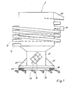
- Fig. die Seitenansicht der erfindungsgemäßen Vorrichtung,
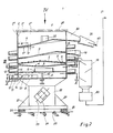
- Fig. die Ansicht von Fig. mit einer Schnittansicht durch den Behälter mit daneben angeordnetem Sichter und Förderer,
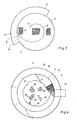
- Fig. 3 einen Schnitt nach der Linie III/III von Fig. 2 auf das Feinsieb mit der darauf angeordneten Führungsspirale,
- Fig. 4 eine Draufsicht in Richtung des Pfeiles IV von Fig. 2 auf den Behälter mit dem Grobsieb und der Innenwendelfläche, und
- Fig. 5 eine Schnittansicht in Richtung V/V von Fig-2 auf das geschlossene Bodenblech mit der Durchgangsöffnung zur zweiten Außenwendelfläche für das Feinkorn.
- Fig. The side view of the device according to the invention,
- 1 is a sectional view through the container with sifter and conveyor arranged next to it,
- 3 shows a section along the line III / III of FIG. 2 on the fine screen with the guide spiral arranged thereon,
- Fig. 4 is a plan view in the direction of arrow IV of Fig. 2 on the container with the coarse screen and the inner spiral surface, and
- Fig. 5 is a sectional view in the direction V / V of Fig-2 on the closed bottom plate with the through opening to the second outer spiral surface for the fine grain.
Gemäß den Fig. 1 und 2 besteht die neue Vorrichtung 1 zur Durchführung des erfindungsgemäßen Verfahrens im wesentlichen aus einem zylindrischen Behälter 2, in dem untereinander ein Grobsieb 3, ein Trichter 4 mit zentraler Öffnung 5, eine Führungsspirale 6, ein Feinsieb 7 und ein abschließendes Bodenblech 8 angeordnet sind. Im Bodenblech 8 ist lösbar eine über die Muttern 9 verstellbare Spannvorrichtung 10 für das Feinsieb 7 angebracht. Außerdem befindet sich an der Innenwandung 2' des Behälters 2 eine Innenwendelfläche 11, die vom Rand 3' des von der Mitte zur Innenwandung 2' hin geneigten Grobsiebes 3 bis an den oberen, den Ausgangsbereich 2" des Behälters 2 bildenden Rand ansteigt.1 and 2, the
An der Behälteraußenwandung 2"' ist eine erste Außenwendelfläche 12 zur Aufnahme des vom Feinsieb 7 zurückgehaltenen Stoffgemisches mit Überkorngröße, kurz Überkorn genannt, und darunter eine zweite Außenwendelfläche 12 zur Aufnahme des vom Feinsieb 7 durchgelassenen Produktes mit Feinkorngröße, nachfolgend kurz Feinkorn genannt, angeordnet. Die erste Außenwendelfläche 12 fördert das vom Feinsieb 7 zurückgehaltene und von der Führungsspirale 6 zu der ersten Austrittsöffnung 14 geleitete Überkorn oberhalb des Grobsiebes 3 durch eine dritte Durchgangsöffnung 15 in den Innenraum des Behälters 2 zurück. Dadurch entsteht vom Innenraum des Behälters 2 über das Grobsieb 3, den Trichter 4 mit der zentralen Öffnung 5 und von dort über das Feinsieb 7 und die Führungsspirale 6 und schließlich über die erste Außenwendelfläche 12 ein Rezirkulationskreislauf für das Überkorn. Darunter wird im vorliegenden Fall ein Produkt mit einer Korngröße verstanden, die größer als die Sieböffnungen 7' des Feinsiebes 7 ist.Arranged on the outer wall of the
Aberhalb des Bodenbleches 8 ist an dessen Rand 8' eine zweite Durchgangsöffnung 16 in der Behälterwandung angeordnet. An diese zweite Durchgangsöffnung 16 schließt sich die zweite, ansteigende Außenwendelfläche 13 für die Aufwärtsförderung des vom Feinsieb 7 durchgelassenen Feinkorns an. Diese zweite Außenwendelfläche 13 ist an ihrem Boden 13' mit einem Hohlraum 17 zur Durchströmung eines Wärmeübertragungsmediums versehen. Dadurch kann beispielsweise das von der zweiten Außenwendelfläche 13 aufgenommene Feinkorn auf dem Wege bis zum Austrag 18 gekühlt, von dort in einen Sichter 19 und daraus schließlich über einen, z.B. pneumatischen Förderer 20 in Richtung des Pfeiles 21 zu einem nichtdargestellten Silo gefördert werden.However, a second through opening 16 is arranged in the container wall at the edge 8 'of the
Der Behälter 2 ist auf einem zentralen Sockel 22 angeordnet, an dem zwei mit ihren Längsachsen 23 um 90' räumlich zueinander versetzte Schwingungserreger 24 und mehrere zur Bodenfläche 25 hin elastische Abstützungen 26 aufweisende Füße 27 befestigt sind. Der Schwingungserreger 24 kann sowohl elektromagnetisch elektrodynamisch als auch als Resonanzschwinger ausgebildet werden.The
Der Behälter 2 ist oberhalb der Innenwendelfläche 11 und der ersten und zweiten Außenwendelfläche 12, 13 von einem mit ihm lösbar verbundenen, strichpunktiert angedeuteten Durchschlagrost 28 abgedeckt.The
Wie aus der Fig. 3 in Verbindung mit Fig. 2 entnommen werden kann, ist der Ursprung 6', der aus einem Blechstreifen bestehenden Führungsspirale 6 unterhalb der zentralen Öffnung 5 des Trichters 4 angeordnet, während das Ende 6" der Führungsspirale etwa tangential in der ersten Durchgangsöffnung 14 im Behälter 2 endet, an die sich wiederum die erste Außenwendelfläche 12 anschließt.As can be seen from FIG. 3 in connection with FIG. 2, the origin 6 ', the
Wie aus Fig. 4 in Verbindung mit Fig. 2 entnehmbar ist, besteht die Innenwendelfläche 11 aus einem Flachstahl, dessen Fläche zur Behälterinnenwandung 2' um einen Winkel "A von 5' bis 10' geneigt ist. Die Breite B der Innenwendelfläche 11 nimmt in Richtung ihrer Steigung zu und ist an ihrer freien Rundkante 11' mit zerreibenden Zacken 29 versehen. In der Nähe des Ausgangsbereiches 30 der Innenwendelfläche 11 aus dem Behälter 2 ist letztere als Sieb 31 ausgebildet und davor eine die Innenwendelfläche 11 sperrende sowie von außen betätigbare Sperrklappe 32 angeordnet. Zur raschen Auswechselbarkeit sind die Innenwendelfläche 11 und die erste und zweite Außenwendelfläche 12, 13 lösbar am Behälter 2 befestigt oder mit lösbaren, nichtdargestellten Verschleißauflagen versehen.As can be seen from FIG. 4 in connection with FIG. 2, the
Wie ferner aus Fig. 4 entnommen werden kann, ist das Grobsieb 3 als Abriebblech, ähnlich einer Reibe bzw. Raspel, ausgebildet. Dabei kann der Abriebeffekt zum einen durch senkrecht zur Förderrichtung in Richtung des Pfeiles 33 verlaufende Längsschlitze 34 und/ oder mit scharfkantigen Erhöhungen bzw. Noppen 35 und/oder mit halbmondförmigen, scharfkantigen Ausklinkungen 36 erhöht werden. Grundsätzlich ist jede Ausbildung des Grobsiebes 3 geeignet, die den Abriebeffekt des permanent durch die Schwingungen umgewälzten Stoffgemisches erhöht. Insofern muß das Grobsieb 3 nicht nur als Sieb-, sondern auch als das Stoffgemisch zerkleinernde Sichtvorrichtung betrachtet werden.As can also be seen from FIG. 4, the
Fig. 5 zeigt die Draufsicht auf das Bodenblech 8 entlang der Schnittlinie V/V von Fig. 2. Das auf ihm befindliche Feinkorn wird durch die Schwing- und Rüttelbewegungen der Vorrichtung 1 entlang einem Leitblech 37 zur zweiten Durchgangsöffnung 16 in den Behälter 2 geleitet, von wo es auf die zweite Außenwendelfläche 13 ansteigend zu deren Austrag 18 und von dort in den Sichter 19 gefördert wird.5 shows the top view of the
Das neue Verfahren zur Aufbereitung von Gießereialtsand mit Bestandteilen unterschiedlicher Korngröße arbeitet folgendermaßen:
- Über den Durchschlagrost 28 gelangt der Gießereialtsand in den
Innenraum des Behälters 2. Da der Behälter 2 über dieSchwingungserreger 24 in Schwing- und Rüttelbewegungen versetzt wird, beginnt die Zerkleinerung des Gießereialtsandes bereits am Durchschlagrost 28, ohne daß für sein Einbringen eine zusätzliche Fördereinrichtung erforderlich ist. ImInnenraum des Behälters 2 wird das Gemisch des Gießereialtsandes oberhalb des Grobsiebes 3 durch ständige Kreis- und Schubbewegungen umgewälzt und anden zerreibenden Zacken 29der Innenwendelfläche 11 sowie ander Unterseite 11" der sich in Richtung aufden Ausgangsbereich 30 verbreiternden Innenwendelfläche 11 gebrochen. Für einen zusätzlichen Abrieb sorgtdas Grobsieb 3 mit seinen zu Fig. 4 beschriebenen Längsschlitzen 34, scharfkantigen Erhöhungen 35 und scharfkantigen Ausklinkungen 36, ähnlich einer Reibe bzw. einer Raspel. Dasdurch das Grobsieb 3 fallende Stoffgemisch aus Überkorn und Feinkorn fällt auf den Trichter 4, von wo es durch die zentrale Öffnung 5 auf das Feinsieb 7 gelangt. Das durch das Feinsieb 7 fallende Feinkorn gelangt überdas Bodenblech 8 auf diezweite Außenwendelfläche 13, auf der es durch dievon den Schwingungserregern 24 herrührenden Schwingungen aufwärts in Richtung des Austrages 18 und von dort inden Sichter 19 gefördert wird. Auf dem Wege von der zweiten Durchgangsöffnung 16bis zum Austrag 18 der zweiten Außenwendelfläche 13 kann das Feinkorn durch eindurch den Hohlraum 17 am Boden 13' strömendes Wärmeübertragungsmedium gekühlt werden. Letzeres gilt für das Feinkorn des Gießereiformsandes. Das auf dem Feinsieb 7 verbleibende Überkorn wird entlang der zu Fig-3beschriebenen Führungsspirale 6 auf möglichst langem Weg zur ersten Durchgangsöffnung 14 befördert. Der durch dieSpirale 6 bewirkte Führungsweg ist bewußt deshalb so lang gestaltet, um das auf dem Feinsieb 7 befindliche Überkorn einem Reibungseffekt zu unterziehen. Dadurch wird nicht nur ein reiner Sieb-, sondern ein zusätzlicher Reib- und damit Sichtungsprozeß erzwungen. Von der ersten Außenwendelfläche 12 gelangt das Überkorn zu der dritten Durchtrittsöffnung 15, von wo es in denInnenraum des Behälters 2 zurückfällt. Auf diese Weise entsteht für das Überkorn ein Rezirkulationskreislauf. Zur Nachspannung des Feinsiebes 7 dient dieSpannvorrichtung
- The foundry sand enters the interior of the
container 2 through the perforated grate 28. Since thecontainer 2 is set into oscillating and vibrating movements by means of thevibration exciters 24, the sanding of the foundry sand begins at the perforated grate 28 without an additional conveying device being required for its introduction . In the interior of thecontainer 2, the mixture of the foundry sand above thecoarse sieve 3 is circulated by constant circular and pushing movements and broken on theabrasive prongs 29 of theinner spiral surface 11 and on theunderside 11 "of theinner spiral surface 11 widening in the direction of theexit area 30 An additional abrasion is provided by thecoarse sieve 3 with its longitudinal slots 34 described in FIG. 4, sharp-edged elevations 35 and sharp-edgednotches 36, similar to a grater or a rasp. The mixture of oversize and fine grain falling through thecoarse sieve 3 falls onto the funnel 4, from where it reaches the fine sieve 7 through the central opening 5. The fine grain falling through the fine sieve 7 passes via thebase plate 8 to the second outerhelical surface 13, on which it moves upwards in the direction of thedischarge 18 and is promoted from there into theclassifier 19. On the way from the tw From the throughopening 16 to thedischarge 18 of the secondouter spiral surface 13, the fine grain can be cooled by a heat transfer medium flowing through thecavity 17 at the bottom 13 '. The latter applies to the fine grain of the foundry sand. The oversized grain remaining on the fine sieve 7 is conveyed along theguide spiral 6 described for FIG . 3 as long as possible to thefirst passage opening 14. The guide path effected by thespiral 6 is therefore deliberately designed to be long enough to subject the oversize material on the fine sieve 7 to a friction effect. This forces not only a pure sieving process, but an additional rubbing and therefore screening process. The oversize grain reaches the third passage opening 15 from the firstouter spiral surface 12, from where it falls back into the interior of thecontainer 2. This creates a recirculation cycle for the oversize. Thetensioning device
Das nicht durch das Grobsieb fallende Abfallprodukt wandert auf der vom Rand 3' des Grobsiebes 3 ansteigenden Innenwendelfläche 11 aufwärts in Richtung des Ausgangsbereiches 30. Bei einem Gießereiformstoffgemisch würden auf der Innenwendelfläche 11 beispielsweise die zur Armierung dienenden Metallteile hinaufbefördert. Da diese Metallteile jedoch zumindest zum Teil wiederverwendbar sind, ist der Ausdruck "Abfallprodukt" nicht wörtlich, sondern dahingehend zu verstehen, daß darunter solche Stoffe fallen, deren Korngröße größer als die größte Sieböffnung des Grobsiebes 3 ist.The waste product not falling through the coarse sieve travels upwards on the inner
Während der Dauer des Zerkleinerungsprozesses im Innenraum des Behälters 2 nimmt die aus Fig. 4 ersichtliche Sperrklappe 32 die darin eingezeichnete Sperrstellung ein. Dadurch ist der Ausgangsbereich 30 der Innenwendelfläche 11 gesperrt. Sobald die nicht durch das Grobsieb 3 fallenden groben Bestandteile, kurz Abfallprodukte genannt, aus dem Behälter 2 herausbefördert werden sollen, wird die Sperrklappe 32 in Richtung des Pfeiles 38 gemäß Fig. 4 verschwenkt und damit der Weg von der Innenwendelfläche 11 zu ihrem Ausgangsbereich 30 freigegeben. Bevor jedoch das auf den Innenwendelfläche 11 hinaufbeförderte Abfallprodukt den Ausgangsbereich 30 erreicht, wird es gezwungen, die Siebfläche 31 zu durchlaufen, auf der es von anhaftenden Feinkornbestandteilen gesäubert wird. Vom Ausgangsbereich 30 fällt das Abfallprodukt auf die in den Fig. 1 und 2 angedeutete Rutsche 39 und von dort in Richtung des Pfeiles 40 zu einem vorgesehenen Depot. Zur ünterstützung der Förderwirkung des Abfallproduktes auf der Innenwendelfläche 11 ist es von Vorteil, wenn diese unter einem Winkel *A zur Behälterinnenwandung 2' hin geneigt ist, so daß sie mit letzterer trotz ihrer flachen Ausbildung eine Rinne bildet. Dabei ist ein Winkel *A von 5° bis 10° besonders vorteilhaft.During the comminution process in the interior of the
Das neue Verfahren sowie die neue Vorrichtung zeichnen sich durch eine besondere Kompaktheit, einen geringen Raumbedarf und durch einen hohen Wirkungsgrad im Hinblick auf die Zerkleinerung von Stoffgemischen - hier von Gießereialtsanden - aus. Da zudem das gesamte Verfahren und die gesamte Vorrichtung von nur einer einzigen Schwingungsquelle, nämlich den Schwingungserregern 24, betrieben werden, können erhebliche Ersparnisse der Betriebskosten erzielt werden, die bei vergleichbaren bekannten Verfahren für zusätzliche Fördereinrichtungen auch zusätzlich erbracht werden müssen.The new process and the new device are characterized by a special compactness, a small space requirement and a high efficiency with regard to the comminution of material mixtures - here from foundry sands. In addition, since the entire method and the entire device are operated by only a single vibration source, namely the
Es versteht sich, daß die vorstehende Vorrichtung je nach der Art des darin zu behandelnden Stoffgemisches auch verschiedene Abwandlungen zuläßt. So kann beispielsweise bei einem aus nur zwei Komponenten bestehenden Stoffgemisch das Feinsieb 7 durch das Bodenblech 8 ersetzt werden und die zweite Außenwendelfläche 13 in Fortfall geraten. Bei mehr als drei Stoffkomponenten läßt die erfindungsgemäße Vorrichtung jedoch auch noch die Anordnung mehrerer Siebe 7, die unter Umständen wie das Grobsieb 3 ausgebildet sein können sowie untereinander als auch nebeneinander angeordnete, zusätzliche Außenwendelflächen zu. Der Steigungswinkel, der in der Regel gleichlaufend ansteigenden Außenwendelflächen 12, 13, kann gleichfalls den Korngrößen der einzelnen Stoffkomponenten der Zwischen-und Fertigprodukte angepaßt werden.It goes without saying that the above device also permits various modifications, depending on the type of substance mixture to be treated therein. For example, in the case of a material mixture consisting of only two components, the fine sieve 7 can be replaced by the


Claims (18)
Priority Applications (1)
| Application Number | Priority Date | Filing Date | Title |
|---|---|---|---|
| AT83106667T ATE22824T1 (en) | 1982-07-12 | 1983-07-07 | METHOD AND DEVICE FOR THE PRODUCTION OF SUBSTANCES OF DIFFERENT GRAIN SIZES FROM MIXTURES. |
Applications Claiming Priority (2)
| Application Number | Priority Date | Filing Date | Title |
|---|---|---|---|
| DE3226049 | 1982-07-12 | ||
| DE3226049A DE3226049C2 (en) | 1982-07-12 | 1982-07-12 | Method and device for the preparation of foundry sand |
Publications (2)
| Publication Number | Publication Date |
|---|---|
| EP0107752A1 EP0107752A1 (en) | 1984-05-09 |
| EP0107752B1 true EP0107752B1 (en) | 1986-10-15 |
Family
ID=6168263
Family Applications (1)
| Application Number | Title | Priority Date | Filing Date |
|---|---|---|---|
| EP83106667A Expired EP0107752B1 (en) | 1982-07-12 | 1983-07-07 | Process and device for producing variable grain size materials from mixtures |
Country Status (3)
| Country | Link |
|---|---|
| EP (1) | EP0107752B1 (en) |
| AT (1) | ATE22824T1 (en) |
| DE (1) | DE3226049C2 (en) |
Families Citing this family (12)
| Publication number | Priority date | Publication date | Assignee | Title |
|---|---|---|---|---|
| US4563268A (en) * | 1984-10-09 | 1986-01-07 | Polysar Financial Services S.A. | Method of discharging particles from a vibrating filter screen |
| US4906356A (en) * | 1988-09-30 | 1990-03-06 | General Kinematics Corporation | Material classifying apparatus |
| US6000644A (en) * | 1997-07-31 | 1999-12-14 | General Kinematics Corporation | Method and apparatus for reclaiming foundry sand |
| US6691765B2 (en) | 2001-08-07 | 2004-02-17 | Noram Technology, Ltd. | Products for the manufacture of molds and cores used in metal casting and a method for their manufacture and recycle from crushed rock |
| DE102009031277A1 (en) * | 2009-06-30 | 2011-01-13 | WEBAC Gesellschaft für Maschinenbau mbH | Method for cleaning used foundry sand, by separating the foundry sand in fractions according to the criterion of the grain size, where an old-sand fraction with small grain size and an overgrain fraction with large grain size are created |
| PL231029B1 (en) * | 2012-07-25 | 2019-01-31 | Akademia Gorniczo Hutnicza Im Stanislawa Staszica W Krakowie | Device for regeneration of the spent vibratory casting mass |
| CN106946000A (en) * | 2017-05-09 | 2017-07-14 | 新乡市东振机械制造有限公司 | A kind of cooled elevator |
| CN113402136B (en) * | 2021-06-17 | 2023-10-24 | 浙江宜可欧环保科技有限公司 | Oil-containing sludge screening and heat washing combined pretreatment method and device |
| CN113575999A (en) * | 2021-07-22 | 2021-11-02 | 漳州福荣饲料科技有限公司 | Cleaning device that pig feed production used |
| CN113617669A (en) * | 2021-08-11 | 2021-11-09 | 深圳市惠亿达电子科技有限公司 | Hardware screw intelligent sorting device for hardware sales |
| CN116674214B (en) * | 2023-05-21 | 2023-11-24 | 江苏万恒铸业有限公司 | Cast steel casting waste recycling device with screening function |
| CN116986914B (en) * | 2023-08-24 | 2024-02-13 | 衡阳凯新特种材料科技有限公司 | Preparation system and method of silicon nitride biological ceramic material |
Family Cites Families (6)
| Publication number | Priority date | Publication date | Assignee | Title |
|---|---|---|---|---|
| DE1456805A1 (en) * | 1966-01-08 | 1968-12-19 | Rose Forgrove Ltd | Cylindrical vibrating conveyor with a rising conveyor path |
| DE2037371C3 (en) * | 1969-07-22 | 1975-05-28 | General Kinematics Corp., Barrington, Ill. (V.St.A.) | Vertical vibratory conveyor for conveying lumpy or granular material |
| DE2739941A1 (en) * | 1977-04-15 | 1979-03-15 | Richards Structural Steel Co L | Vibratory conveyor with elastic mountings - has buffer rods spaced apart above inclined surface and inclined to it in comb pattern |
| US4205796A (en) * | 1978-03-03 | 1980-06-03 | Rexnord Inc. | Vibrating reclaimer of foundry mold material |
| US4267919A (en) * | 1979-05-21 | 1981-05-19 | Rexnord Inc. | Vibrating spiral conveyor drive |
| DE3021490C2 (en) * | 1980-06-07 | 1985-11-21 | Alb. Klein Gmbh & Co Kg, 5241 Niederfischbach | Method and device for preparing mixtures of sand bulbs |
-
1982
- 1982-07-12 DE DE3226049A patent/DE3226049C2/en not_active Expired
-
1983
- 1983-07-07 EP EP83106667A patent/EP0107752B1/en not_active Expired
- 1983-07-07 AT AT83106667T patent/ATE22824T1/en not_active IP Right Cessation
Also Published As
| Publication number | Publication date |
|---|---|
| ATE22824T1 (en) | 1986-11-15 |
| EP0107752A1 (en) | 1984-05-09 |
| DE3226049C2 (en) | 1984-08-30 |
| DE3226049A1 (en) | 1984-01-12 |
Similar Documents
| Publication | Publication Date | Title |
|---|---|---|
| DE2535382C3 (en) | Spreader | |
| EP2704838B1 (en) | Device for the impact crushing and dispensing of materials, in particular wood, in several fractions | |
| EP0107752B1 (en) | Process and device for producing variable grain size materials from mixtures | |
| DE2202311C2 (en) | Plant for the recovery of sand from the mixture resulting from the blasting of synthetic resin-bonded molds | |
| DE2519328C2 (en) | Device for the recovery of foundry sand from lumps of previously used foundry sand | |
| DE4033619C2 (en) | ||
| EP0975457B1 (en) | Device for fractionating and scattering specially fibrous particles | |
| DE3445366A1 (en) | DEVICE FOR GRINDING, GRINDING, CRUSHING, SCRUBBING, SORTING BY SIZE AND / OR CLASSIFYING MATERIAL | |
| EP0434995B1 (en) | Silo with a discharging device | |
| DE3305383C2 (en) | Pre-screen for separating mixed waste and procedures for operating the pre-screen | |
| DE3626044C2 (en) | ||
| CH664946A5 (en) | DEVICE TO PREVENT OVERLOAD OF CONVEYING EQUIPMENT. | |
| DE3328060A1 (en) | SORTING DEVICE | |
| DE2708961A1 (en) | METHOD AND DEVICE FOR REDUCING THE RESIN CONTENT OF USED FOUNDRY SAND | |
| DE4434748C2 (en) | Method and device for separating a bulk material mixture | |
| WO1994020229A1 (en) | Bulk material conveyor | |
| EP1063006A2 (en) | Process for mixing bulk material and mixing apparatus | |
| DE8219912U1 (en) | DEVICE FOR PRODUCING SUBSTANCES OF DIFFERENT GRAIN SIZE FROM MIXTURES | |
| DE4009696C2 (en) | ||
| DE912287C (en) | Feeding device for grist mills | |
| DE1300580B (en) | Cooling system for glazing and freezing solid particles | |
| DE3734270A1 (en) | Impact-head crusher having two rotors | |
| DE2651393C3 (en) | Device for processing residual concrete and other similar suspensions | |
| DE1220597B (en) | Device for pouring chipboard or the like. Moldings | |
| DE4221391C2 (en) | Device for the disposal of liquid material waste, comprising tufts of chips, core parts and small chips, from workpiece machining |
Legal Events
| Date | Code | Title | Description |
|---|---|---|---|
| PUAI | Public reference made under article 153(3) epc to a published international application that has entered the european phase |
Free format text: ORIGINAL CODE: 0009012 |
|
| AK | Designated contracting states |
Designated state(s): AT BE CH FR GB IT LI NL SE |
|
| 17P | Request for examination filed |
Effective date: 19840607 |
|
| GRAA | (expected) grant |
Free format text: ORIGINAL CODE: 0009210 |
|
| AK | Designated contracting states |
Kind code of ref document: B1 Designated state(s): AT BE CH FR GB IT LI NL SE |
|
| PG25 | Lapsed in a contracting state [announced via postgrant information from national office to epo] |
Ref country code: IT Free format text: LAPSE BECAUSE OF FAILURE TO SUBMIT A TRANSLATION OF THE DESCRIPTION OR TO PAY THE FEE WITHIN THE PRESCRIBED TIME-LIMIT;WARNING: LAPSES OF ITALIAN PATENTS WITH EFFECTIVE DATE BEFORE 2007 MAY HAVE OCCURRED AT ANY TIME BEFORE 2007. THE CORRECT EFFECTIVE DATE MAY BE DIFFERENT FROM THE ONE RECORDED. Effective date: 19861015 |
|
| REF | Corresponds to: |
Ref document number: 22824 Country of ref document: AT Date of ref document: 19861115 Kind code of ref document: T |
|
| ET | Fr: translation filed | ||
| PLBE | No opposition filed within time limit |
Free format text: ORIGINAL CODE: 0009261 |
|
| STAA | Information on the status of an ep patent application or granted ep patent |
Free format text: STATUS: NO OPPOSITION FILED WITHIN TIME LIMIT |
|
| 26N | No opposition filed | ||
| PGFP | Annual fee paid to national office [announced via postgrant information from national office to epo] |
Ref country code: SE Payment date: 19920626 Year of fee payment: 10 |
|
| PG25 | Lapsed in a contracting state [announced via postgrant information from national office to epo] |
Ref country code: SE Effective date: 19930708 |
|
| PGFP | Annual fee paid to national office [announced via postgrant information from national office to epo] |
Ref country code: AT Payment date: 19930730 Year of fee payment: 11 |
|
| PGFP | Annual fee paid to national office [announced via postgrant information from national office to epo] |
Ref country code: NL Payment date: 19930731 Year of fee payment: 11 |
|
| PGFP | Annual fee paid to national office [announced via postgrant information from national office to epo] |
Ref country code: CH Payment date: 19930804 Year of fee payment: 11 |
|
| PG25 | Lapsed in a contracting state [announced via postgrant information from national office to epo] |
Ref country code: AT Effective date: 19940707 |
|
| PG25 | Lapsed in a contracting state [announced via postgrant information from national office to epo] |
Ref country code: LI Effective date: 19940731 Ref country code: CH Effective date: 19940731 |
|
| PGFP | Annual fee paid to national office [announced via postgrant information from national office to epo] |
Ref country code: GB Payment date: 19940815 Year of fee payment: 12 |
|
| PGFP | Annual fee paid to national office [announced via postgrant information from national office to epo] |
Ref country code: BE Payment date: 19940817 Year of fee payment: 12 |
|
| PGFP | Annual fee paid to national office [announced via postgrant information from national office to epo] |
Ref country code: FR Payment date: 19940926 Year of fee payment: 12 |
|
| EUG | Se: european patent has lapsed |
Ref document number: 83106667.5 Effective date: 19940210 |
|
| PG25 | Lapsed in a contracting state [announced via postgrant information from national office to epo] |
Ref country code: NL Effective date: 19950201 |
|
| NLV4 | Nl: lapsed or anulled due to non-payment of the annual fee | ||
| REG | Reference to a national code |
Ref country code: CH Ref legal event code: PL |
|
| PG25 | Lapsed in a contracting state [announced via postgrant information from national office to epo] |
Ref country code: GB Effective date: 19950707 |
|
| PG25 | Lapsed in a contracting state [announced via postgrant information from national office to epo] |
Ref country code: BE Effective date: 19950731 |
|
| BERE | Be: lapsed |
Owner name: THAL HELMUT Effective date: 19950731 |
|
| GBPC | Gb: european patent ceased through non-payment of renewal fee |
Effective date: 19950707 |
|
| PG25 | Lapsed in a contracting state [announced via postgrant information from national office to epo] |
Ref country code: FR Effective date: 19960430 |
|
| REG | Reference to a national code |
Ref country code: FR Ref legal event code: ST |
|
| REG | Reference to a national code |
Ref country code: FR Ref legal event code: ST |
|
| REG | Reference to a national code |
Ref country code: FR Ref legal event code: ST |