EP0107699B1 - Cargo restraining device - Google Patents
Cargo restraining device Download PDFInfo
- Publication number
- EP0107699B1 EP0107699B1 EP83901511A EP83901511A EP0107699B1 EP 0107699 B1 EP0107699 B1 EP 0107699B1 EP 83901511 A EP83901511 A EP 83901511A EP 83901511 A EP83901511 A EP 83901511A EP 0107699 B1 EP0107699 B1 EP 0107699B1
- Authority
- EP
- European Patent Office
- Prior art keywords
- pallet
- serrated member
- platform
- cargo
- floor
- Prior art date
- Legal status (The legal status is an assumption and is not a legal conclusion. Google has not performed a legal analysis and makes no representation as to the accuracy of the status listed.)
- Expired
Links
- 230000000452 restraining effect Effects 0.000 title claims description 15
- 239000002783 friction material Substances 0.000 claims description 2
- 230000000903 blocking effect Effects 0.000 description 3
- 239000002184 metal Substances 0.000 description 3
- 229910000831 Steel Inorganic materials 0.000 description 1
- 230000001133 acceleration Effects 0.000 description 1
- 239000000969 carrier Substances 0.000 description 1
- 238000001816 cooling Methods 0.000 description 1
- 238000006073 displacement reaction Methods 0.000 description 1
- 230000000694 effects Effects 0.000 description 1
- 230000037431 insertion Effects 0.000 description 1
- 238000003780 insertion Methods 0.000 description 1
- 239000000463 material Substances 0.000 description 1
- 238000005057 refrigeration Methods 0.000 description 1
- 239000010959 steel Substances 0.000 description 1
- 238000006467 substitution reaction Methods 0.000 description 1
Images


Classifications
-
- B—PERFORMING OPERATIONS; TRANSPORTING
- B60—VEHICLES IN GENERAL
- B60P—VEHICLES ADAPTED FOR LOAD TRANSPORTATION OR TO TRANSPORT, TO CARRY, OR TO COMPRISE SPECIAL LOADS OR OBJECTS
- B60P7/00—Securing or covering of load on vehicles
- B60P7/06—Securing of load
- B60P7/08—Securing to the vehicle floor or sides
- B60P7/0892—Securing to the vehicle floor or sides by preventing lateral movement of the load, e.g. using stop blocks
Definitions
- This invention relates to a cargo restraining device and in particular to a device having a platform for association with a pallet loaded with cargo and for retraining the pallet against movement when placed in a vehicular carrier.
- United States Patent No. 4 147 112 discloses a cargo support brace comprising:
- the ground contacting surface portion of the lower floor contacting member may be provided with a plurality of surface gripping projections thereon. It is to be appreciated that the lower floor contacting member is located entirely below the pallet and its cargo load.
- the brace of United States Patent No. 4 147 112 is intended to avoid banding or blocking of palletized cargo loads, and is reasonably effective under certain conditions of use, it has been found inadequate for maintaining load integrity under a number of conditions, including when used in truck trailers mounted for piggy-back service on railraod cars.
- the palletized cargo load already on its respective brace is loaded onto the carrier.
- the spikes cannot be used on the metal floors which are found in refrigerated trucks and railroad cars; and further, it is found that the mere substitution of rubber pads for the spikes does not solve this problem.
- United States Patent No. 1,559,827 relates to a freight anti-creeping device including a platform having spikes in its underside for gripping the floor, and a projecting lug on its upper face to which the cargo is wired. This projecting lug requires an opening in the cargo, or else the cargo must be mounted around the lug.
- United States Patent No. 1,638,612 relates to a device for shipping boxes, which includes anti- skid plates between the boxes and the floor and clamp bars over the boxes, which are drawn to the floor by rods anchored adjacent the floor, blocks being secured to the boxes for preventing movement between the clamp bars and the boxes.
- United States Patent No. 2,420,640 to Acteson relates to a demountable pallet crib having frame members which enclose the perimeter of the pallet and form an open-work frame to enclose the cargo.
- United States Patent No. 3307658 discloses a cart apparatus comprising:
- a cargo restraining device for restraining a palletized cargo load mounted within a vehicular carrier, the pallet being of the type including an upper load supporting surface and a lower surface separated from the upper surface by cross-ties, the device comprising:
- handle means pivotally secured to the frame and to the assembly by a hinge pivotally connected to the frame at a first pivot and to the vertically-extending assembly at a second pivot, thereby to define a double pivot
- the handle means and hinge being movable to position whereat the lower end of the assembly is brought into contact with the underlying floor of the carrier and then extended below the level of the pallet to exert an upward jacking force on the adjacent end of the cargo supporting platform, to increase the contact force between the lower end of the assembly and the floor, thus increasing the frictional engagement with the floor
- the second pivot in this position being displaced past its vertically aligned lowermost point of rotation with respect to the first pivot and toward the vertical frame, the vertically-extending assembly being thereby angled with its lower end further away from the vertical frame and platform than its upper end, thereby locking the handle in this position.
- the device of the present invention can secure a palletized load within a vehicular carrier against movement such as creeping or shifting.
- the device of the present invention is simple to use both when fixing in position a palletized load already loaded onto a carrier, and when releasing the palletized load when it reaches its destination.
- the device of the present invention can satisfactorily secure and release a palletized load in a carrier, and requires very little effort to operate, and is simple to construct.
- the device can be used for securing and releasing a palletized load in a carrier of the type intended to refrigerate a load, which carrier is provided with a metal floor with ribs or spaced longitudinally-extending channels which allow cold air to circulate around the cargo.
- the lower end of the assembly comprises a horizontally-extending member at least the lower surface of which comprises a high friction material.
- the device may also include means for releasably and positively engaging a part of the pallet when the horizontal platform is received within the pallet, thereby locking the pallet to the device.
- the means for engaging the pallet may include a serrated member. The teeth may engage the pallet cross-tie.
- the pallet may also include a lever coupled to the serrated member and resiliently biased to tend to urge the serrated member to engage the pallet.
- the serrated member is pivotally connected with respect to a portion of the horizontal platform.
- a preferred embodiment of the device of the present invention is that wherein the means for releasably and positively engaging a part of the pallet includes a serrated member having teeth for engaging a pallet cross-tie member, the serrated member being pivotally secured to a portion of the platform, a movable lever connected to the serrated member, and resilient means tending to urge the lever in that direction which causes the serrated member to engage the pallet, whereby movement of the lever against the resilient means causes the serrated member to rotate, releasing the teeth of the serrated member from said cross-tie.
- the device When the device is brought into association with the pallet, the device may immediately be locked in place by a serrated member which engages a cross-tie or runner of the pallet.
- the pallet can only be released by disengaging the teeth of the serrated member. This can be accomplished by a resiliently biased lever coupled to the serrated member.
- the handle means is pushed downwardly, which pushes the vertically-extending assembly away from the vertical frame and horizontal platform, and toward the floor, i.e. the lower end of the assembly moves below the plane of the pallet. This in turn tends to lift one edge of the pallet in jack-like fashion, adding the weight of the cargo to the downward force on the vertically-extending assembly.
- the handle locks the vertically-extending member in its extended position restraining the pallet against movement. Since the pallet is also secured to the platform, the cargo is securely held in place.
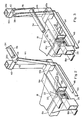
- a palletized load 10 is shown, supported on a conventional pallet 12, the load and pallet being associated with a cargo- restraining device 5 in accordance with the present invention.
- the load 10 can be regarded as being of a type requiring refrigeration in shipment. Usually, therefore, such loads are shipped in refrigerator truck bodies or refrigerated railway cars.
- the floors of these carriers commonly comprise steel or the like, and channels or troughs often extend lengthwise in the carrier floors to enable refrigerated air to be circulated for load cooling.
- the pallet 12 generally comprises an upper supporting surface 14 comprising a plurality of wooden planks, and a lower surface 16 comprised of similar planks, with the upper and lower surfaces being separated by cross-ties 15, one of which 15a ( Figures 2 and 3) is at approximately the centre of the pallet.
- the cross-tie 15a slides into a slot 17 between two generally triangular-shaped plates 18, 19 ( Figures 5 and 6), which comprise the horizontal portion of the generally L-shaped device 5, and which thus form a platform for the loaded pallet.
- the side walls 51 of plates 18 and 19 which abound slot 17 are bevelled at 53 toward their rear, to facilitate insertion of the platform into the space between the upper surface 14 and the lower surface 16 of the pallet.
- Cross-tie 15a is, in the illustrated embodiment, held or locked in its received position by a serrated member 20, which pivots about a pin 22, and has teeth 24 which pierce the wooden cross-tie 15a.
- each triangular-shaped plate is secured to a lower horizontal beam 26 of a generally rectangular vertical frame 28 (Figure 1) having upright legs 28a and 28b, and an upper cross-beam 30.
- the upper and lower cross-beams and upright legs of the vertical frame 28 are braced by diagonally extending members 32.
- a handle 34 is secured at each end to a hinge 46 which is pivotally secured to a plate 40 connected to the vertical legs 28a and 28b of the frame by a pin 42: the plate 46 is also pivotally secured by a pin 38 to members 44 of a vertically extending assembly; there is thus in effect formed a double pivot for the handle 34.
- the handle 34 is thus connected at each end, through hinge 46 and pins 38 and 42, to the generally vertically extending assembly which includes the members 44.
- the lower ends of the members 44 are surrounded by bumper guards 47a and 47b, and are connected to a cross-bar 48 carrying on its underside a horizontally extending member 50 secured to the cross-bar by a bolt 52.
- the cross-bar 48 With the handle 34 in the upper position ( Figure 2), the cross-bar 48, and in particular the member 50, is above the plane of the bottom of the pallet 12, and is thus above the carrier floor, or supporting surface.
- the member 50 When the handle 34 is moved to the lowered position ( Figures 1 and 3) however, the member 50 first contacts the underlying floor and then is extended below the pallet 12 and to a position laterally displaced to one side of the frame 28, to prevent movement of the device 5 with the load thereon.
- the horizontally extending member 50 comprises, or is covered with, a high frictional material such as rubber, in order to obtain a greater frictional force from its contact with the floor.
- the serrated member 20 In order to release the pallet after the handle 34 is raised, the serrated member 20 must be disengaged from cross-tie 15a. This is accomplished by moving a lever 54 to the right in a slot 56, the right end 56a of which is larger, or deeper, to allow the lever 54 to drop down.
- the lever 54 is connected to an arm 58 by a bolt or pin 59, the arm 58 being secured to the serrated member 20.
- moving the lever 54 to the right causes the serrated member 20 to pivot counter-clockwise about the pin 22, causing the teeth 24 to disengage the cross-tie 15a, permitting the device to be withdrawn from the pallet 12.
- the lever 54 In order that the cross-tie 15a of the pallet 12 may be engaged when the triangular-shaped plates 18 and 19 are located between the upper and lower surfaces 14 and 16 of the pallet, the lever 54 should, of course, be lifted and moved to the left in the slot 56.
- a spring 60 secured at one end by a hook 62 in an apertured plate 64, and at the other end to a pin 66 in a vertical bracket 68 to which arm 58 is secured by a bolt or pin 59, causes the serrated member 20 to rotate clockwise about the pin 22 so that it is ready to engage the cross-tie 15a.
- a palletized cargo load 10 When in practice, a palletized cargo load 10 is brought into a carrier by a fork-lift truck, it is placed in the desired position, and then a cargo restraining device is brought up so that the cross- tie 15a is placed between the triangular-shaped plates 18 and 19 so that it rests in the slot 17. If lever 54 has been returned to its original position (to the left in slot 56) as it should have been after the device was removed from a previous pallet, the teeth 24 of the serrated member 20 will pierce the wooden cross-tie 15a and firmly hold it in place.
- the handle 34 is grasped and displaced downwardly while pushing against the frame 28, which will result in the horizontal member 50 contacting the carrier floor and then slightly tilting the load as previously discussed, to restrain movement of the device 5. Frictional contact of the horizontal member 50 is increased by the weight of the load on the pallet 12 which has tilted upwardly at its rear end, placing further force on the horizontal member 50.
- the palletized cargo is firmly secured and prevented from moving while it is being transported.
- the handle 34 Upon reaching its destination, to release the pallet with its cargo load, the handle 34 is returned to its upper position which lifts the horizontal member 50 off the carrier floor.
- the lever 54 is moved to the right, e.g. by moving it with a foot, and this causes the serrated member 20 to move counter-clockwise, releasing the teeth 24 from the cross-tie 15a.
- the restraining device can now be removed from the pallet.
Landscapes
- Engineering & Computer Science (AREA)
- Transportation (AREA)
- Mechanical Engineering (AREA)
- Pallets (AREA)
- Air Bags (AREA)
- Handcart (AREA)
Priority Applications (1)
| Application Number | Priority Date | Filing Date | Title |
|---|---|---|---|
| AT83901511T ATE25043T1 (de) | 1982-04-20 | 1983-03-25 | Vorrichtung zum abstuetzen von lasten. |
Applications Claiming Priority (2)
| Application Number | Priority Date | Filing Date | Title |
|---|---|---|---|
| US370131 | 1982-04-20 | ||
| US06370131 US4515506B1 (en) | 1982-04-20 | 1982-04-20 | Pallet cargo restraining device |
Publications (3)
| Publication Number | Publication Date |
|---|---|
| EP0107699A1 EP0107699A1 (en) | 1984-05-09 |
| EP0107699A4 EP0107699A4 (en) | 1984-09-13 |
| EP0107699B1 true EP0107699B1 (en) | 1987-01-21 |
Family
ID=23458355
Family Applications (1)
| Application Number | Title | Priority Date | Filing Date |
|---|---|---|---|
| EP83901511A Expired EP0107699B1 (en) | 1982-04-20 | 1983-03-25 | Cargo restraining device |
Country Status (10)
| Country | Link |
|---|---|
| US (1) | US4515506B1 (it) |
| EP (1) | EP0107699B1 (it) |
| JP (1) | JPS59500561A (it) |
| AU (1) | AU565140B2 (it) |
| CA (1) | CA1208982A (it) |
| DE (1) | DE3369283D1 (it) |
| IT (1) | IT1200005B (it) |
| MX (1) | MX159480A (it) |
| WO (1) | WO1983003579A1 (it) |
| ZA (1) | ZA831770B (it) |
Families Citing this family (10)
| Publication number | Priority date | Publication date | Assignee | Title |
|---|---|---|---|---|
| KR860001735A (ko) * | 1984-08-13 | 1986-03-22 | 토마스 더블유·톰슨 | 화물 지지장치 |
| US4780034A (en) * | 1986-09-26 | 1988-10-25 | The Boeing Company | Restraint barrier |
| US4872794A (en) * | 1988-05-27 | 1989-10-10 | Halliburton Company | Tank mounting apparatus |
| US4944232A (en) * | 1989-04-25 | 1990-07-31 | Burlington Northern Railroad, A Wholly Owned Subsidiary Of Burlington Northern, Inc. | Dual-purpose depressed center railway flat car |
| US5096018A (en) * | 1991-02-14 | 1992-03-17 | Lifting Technologies, Inc. | Method and apparatus for securing a manbasket to a forklift |
| GB2268156B (en) * | 1992-06-30 | 1996-03-20 | James Edward Douglass | Support member |
| MX9501388A (es) * | 1994-03-16 | 1997-02-28 | H E Butt Grocery Company | Bloqueador de carga. |
| US8894037B1 (en) * | 2011-07-20 | 2014-11-25 | Jeffrey L. Brauer | Lift truck platform apparatus and methods for transporting rolling racks |
| CN111038908B (zh) * | 2019-12-23 | 2024-04-09 | 南京熊猫电子股份有限公司 | 一种可以锁定的浮动承载放置架及货物位置调整和锁定方法 |
| US11377019B1 (en) | 2020-04-07 | 2022-07-05 | The United States Of America As Represented By The Secretary Of The Navy | Container truckload restraint feature (CTRF) incorporated in extruded side wall (ESW) ordnance containers |
Citations (1)
| Publication number | Priority date | Publication date | Assignee | Title |
|---|---|---|---|---|
| US4147112A (en) * | 1977-08-01 | 1979-04-03 | Green Carlos J | Cargo support |
Family Cites Families (9)
| Publication number | Priority date | Publication date | Assignee | Title |
|---|---|---|---|---|
| US1142088A (en) * | 1914-10-16 | 1915-06-08 | Claude Greene | Load-supporting rack. |
| US1559827A (en) * | 1924-03-01 | 1925-11-03 | Wittman John | Freight-anticreeping device |
| US1638612A (en) * | 1924-06-14 | 1927-08-09 | Studebaker Corp | Shipping device |
| US2420640A (en) * | 1945-06-02 | 1947-05-20 | John J Acteson | Demountable pallet crib |
| US3290051A (en) * | 1964-10-15 | 1966-12-06 | Univ California | Pallet bin carrier |
| US3307658A (en) * | 1965-04-15 | 1967-03-07 | M H Equipment Co Inc | Brake apparatus for carts |
| FR1475891A (fr) * | 1966-02-23 | 1967-04-07 | Saxby | Perfectionnement aux transpalettes |
| US3685460A (en) * | 1970-07-08 | 1972-08-22 | Vincent J Steele Jr | Pallet prop |
| US4317645A (en) * | 1980-07-11 | 1982-03-02 | N. P. Marketing Corporation | Cargo retainer |
-
1982
- 1982-04-20 US US06370131 patent/US4515506B1/en not_active Expired - Fee Related
-
1983
- 1983-03-15 ZA ZA831770A patent/ZA831770B/xx unknown
- 1983-03-25 AU AU14800/83A patent/AU565140B2/en not_active Ceased
- 1983-03-25 JP JP58501487A patent/JPS59500561A/ja active Pending
- 1983-03-25 WO PCT/US1983/000421 patent/WO1983003579A1/en active IP Right Grant
- 1983-03-25 DE DE8383901511T patent/DE3369283D1/de not_active Expired
- 1983-03-25 EP EP83901511A patent/EP0107699B1/en not_active Expired
- 1983-04-06 CA CA000425301A patent/CA1208982A/en not_active Expired
- 1983-04-18 IT IT20636/83A patent/IT1200005B/it active
- 1983-04-20 MX MX196988A patent/MX159480A/es unknown
Patent Citations (1)
| Publication number | Priority date | Publication date | Assignee | Title |
|---|---|---|---|---|
| US4147112A (en) * | 1977-08-01 | 1979-04-03 | Green Carlos J | Cargo support |
Also Published As
| Publication number | Publication date |
|---|---|
| EP0107699A4 (en) | 1984-09-13 |
| IT1200005B (it) | 1989-01-05 |
| JPS59500561A (ja) | 1984-04-05 |
| MX159480A (es) | 1989-06-14 |
| ZA831770B (en) | 1983-11-30 |
| WO1983003579A1 (en) | 1983-10-27 |
| IT8320636A0 (it) | 1983-04-18 |
| AU1480083A (en) | 1983-11-04 |
| AU565140B2 (en) | 1987-09-03 |
| US4515506A (en) | 1985-05-07 |
| CA1208982A (en) | 1986-08-05 |
| US4515506B1 (en) | 1996-01-09 |
| DE3369283D1 (en) | 1987-02-26 |
| EP0107699A1 (en) | 1984-05-09 |
Similar Documents
| Publication | Publication Date | Title |
|---|---|---|
| US6099220A (en) | Cart lock | |
| US5312213A (en) | Wheel chocking system for arresting road vehicles during transportation | |
| US4077532A (en) | Airborne cargo container transporter and transfer system | |
| KR101539124B1 (ko) | 컨테이너를 운송차량의 플랫폼에 고정하기 위한 장치 | |
| US4147112A (en) | Cargo support | |
| EP0107699B1 (en) | Cargo restraining device | |
| US5431525A (en) | Recreational vehicle carrier | |
| US3160117A (en) | Container car | |
| US3653521A (en) | System and apparatus for holding freight containers of vehicles and the like | |
| US3612463A (en) | Wedging device for pallet loads | |
| US3993344A (en) | Transporting system | |
| US5020947A (en) | Automatic locking system | |
| US5378105A (en) | Cargo handling system | |
| US1830998A (en) | Freight handling skid | |
| US4317645A (en) | Cargo retainer | |
| US4756651A (en) | Cargo restraining device for palletized loads | |
| US3695471A (en) | Transport vehicle | |
| US2659914A (en) | Dockboard | |
| US3680491A (en) | Freight bracing system | |
| US3893705A (en) | Transportable rack construction | |
| US2828040A (en) | Safety pallet-storage aid | |
| US3504880A (en) | Truck trailer bracing arrangement for load transferring | |
| US3623688A (en) | Securing means in vehicle-transporting platforms | |
| WO1986001164A1 (en) | Cargo restraining device | |
| US5636952A (en) | Load blocker |
Legal Events
| Date | Code | Title | Description |
|---|---|---|---|
| PUAI | Public reference made under article 153(3) epc to a published international application that has entered the european phase |
Free format text: ORIGINAL CODE: 0009012 |
|
| 17P | Request for examination filed |
Effective date: 19831215 |
|
| AK | Designated contracting states |
Designated state(s): AT BE CH DE FR GB LI LU NL SE |
|
| GRAA | (expected) grant |
Free format text: ORIGINAL CODE: 0009210 |
|
| AK | Designated contracting states |
Kind code of ref document: B1 Designated state(s): AT BE CH DE FR GB LI LU NL SE |
|
| PG25 | Lapsed in a contracting state [announced via postgrant information from national office to epo] |
Ref country code: NL Effective date: 19870121 Ref country code: LI Effective date: 19870121 Ref country code: FR Free format text: THE PATENT HAS BEEN ANNULLED BY A DECISION OF A NATIONAL AUTHORITY Effective date: 19870121 Ref country code: CH Effective date: 19870121 Ref country code: BE Effective date: 19870121 Ref country code: AT Effective date: 19870121 |
|
| REF | Corresponds to: |
Ref document number: 25043 Country of ref document: AT Date of ref document: 19870215 Kind code of ref document: T |
|
| PG25 | Lapsed in a contracting state [announced via postgrant information from national office to epo] |
Ref country code: SE Effective date: 19870131 |
|
| REF | Corresponds to: |
Ref document number: 3369283 Country of ref document: DE Date of ref document: 19870226 |
|
| PG25 | Lapsed in a contracting state [announced via postgrant information from national office to epo] |
Ref country code: LU Free format text: LAPSE BECAUSE OF NON-PAYMENT OF DUE FEES Effective date: 19870331 |
|
| REG | Reference to a national code |
Ref country code: CH Ref legal event code: PL |
|
| EN | Fr: translation not filed | ||
| NLV1 | Nl: lapsed or annulled due to failure to fulfill the requirements of art. 29p and 29m of the patents act | ||
| PLBE | No opposition filed within time limit |
Free format text: ORIGINAL CODE: 0009261 |
|
| STAA | Information on the status of an ep patent application or granted ep patent |
Free format text: STATUS: NO OPPOSITION FILED WITHIN TIME LIMIT |
|
| 26N | No opposition filed | ||
| PGFP | Annual fee paid to national office [announced via postgrant information from national office to epo] |
Ref country code: GB Payment date: 19900331 Year of fee payment: 8 |
|
| PGFP | Annual fee paid to national office [announced via postgrant information from national office to epo] |
Ref country code: DE Payment date: 19900409 Year of fee payment: 8 |
|
| PG25 | Lapsed in a contracting state [announced via postgrant information from national office to epo] |
Ref country code: GB Effective date: 19910325 |
|
| GBPC | Gb: european patent ceased through non-payment of renewal fee | ||
| PG25 | Lapsed in a contracting state [announced via postgrant information from national office to epo] |
Ref country code: DE Effective date: 19920101 |