EP0107490A2 - Matrize - Google Patents
Matrize Download PDFInfo
- Publication number
- EP0107490A2 EP0107490A2 EP83306398A EP83306398A EP0107490A2 EP 0107490 A2 EP0107490 A2 EP 0107490A2 EP 83306398 A EP83306398 A EP 83306398A EP 83306398 A EP83306398 A EP 83306398A EP 0107490 A2 EP0107490 A2 EP 0107490A2
- Authority
- EP
- European Patent Office
- Prior art keywords
- base strip
- extruding
- metallic base
- strip
- plastics
- Prior art date
- Legal status (The legal status is an assumption and is not a legal conclusion. Google has not performed a legal analysis and makes no representation as to the accuracy of the status listed.)
- Granted
Links
- 239000011159 matrix material Substances 0.000 title claims abstract description 53
- 239000004033 plastic Substances 0.000 claims abstract description 73
- 229920003023 plastic Polymers 0.000 claims abstract description 73
- 239000000463 material Substances 0.000 claims abstract description 37
- 238000000034 method Methods 0.000 claims description 23
- 238000004519 manufacturing process Methods 0.000 claims description 16
- 238000001125 extrusion Methods 0.000 claims description 7
- 230000003750 conditioning effect Effects 0.000 claims 1
- 238000005238 degreasing Methods 0.000 claims 1
- 230000002093 peripheral effect Effects 0.000 abstract description 2
- 239000012530 fluid Substances 0.000 abstract 1
- 229910000831 Steel Inorganic materials 0.000 description 7
- 239000010959 steel Substances 0.000 description 7
- 238000010276 construction Methods 0.000 description 6
- 238000007796 conventional method Methods 0.000 description 5
- ATUOYWHBWRKTHZ-UHFFFAOYSA-N Propane Chemical compound CCC ATUOYWHBWRKTHZ-UHFFFAOYSA-N 0.000 description 4
- 238000005520 cutting process Methods 0.000 description 4
- 230000003466 anti-cipated effect Effects 0.000 description 3
- 230000000712 assembly Effects 0.000 description 2
- 238000000429 assembly Methods 0.000 description 2
- 230000001143 conditioned effect Effects 0.000 description 2
- 230000014759 maintenance of location Effects 0.000 description 2
- 239000001294 propane Substances 0.000 description 2
- 239000004727 Noryl Substances 0.000 description 1
- 239000004676 acrylonitrile butadiene styrene Substances 0.000 description 1
- 230000007423 decrease Effects 0.000 description 1
- 238000010586 diagram Methods 0.000 description 1
- 230000000694 effects Effects 0.000 description 1
- 238000005538 encapsulation Methods 0.000 description 1
- 239000002184 metal Substances 0.000 description 1
- 239000007769 metal material Substances 0.000 description 1
- 238000012986 modification Methods 0.000 description 1
- 230000004048 modification Effects 0.000 description 1
- 239000004417 polycarbonate Substances 0.000 description 1
- 229920000515 polycarbonate Polymers 0.000 description 1
- 239000004800 polyvinyl chloride Substances 0.000 description 1
- 229920000915 polyvinyl chloride Polymers 0.000 description 1
- 238000003825 pressing Methods 0.000 description 1
- 238000003303 reheating Methods 0.000 description 1
- 238000011144 upstream manufacturing Methods 0.000 description 1
- 238000004804 winding Methods 0.000 description 1
Images

Classifications
-
- B—PERFORMING OPERATIONS; TRANSPORTING
- B23—MACHINE TOOLS; METAL-WORKING NOT OTHERWISE PROVIDED FOR
- B23P—METAL-WORKING NOT OTHERWISE PROVIDED FOR; COMBINED OPERATIONS; UNIVERSAL MACHINE TOOLS
- B23P15/00—Making specific metal objects by operations not covered by a single other subclass or a group in this subclass
- B23P15/28—Making specific metal objects by operations not covered by a single other subclass or a group in this subclass cutting tools
- B23P15/40—Making specific metal objects by operations not covered by a single other subclass or a group in this subclass cutting tools shearing tools
-
- B—PERFORMING OPERATIONS; TRANSPORTING
- B29—WORKING OF PLASTICS; WORKING OF SUBSTANCES IN A PLASTIC STATE IN GENERAL
- B29C—SHAPING OR JOINING OF PLASTICS; SHAPING OF MATERIAL IN A PLASTIC STATE, NOT OTHERWISE PROVIDED FOR; AFTER-TREATMENT OF THE SHAPED PRODUCTS, e.g. REPAIRING
- B29C48/00—Extrusion moulding, i.e. expressing the moulding material through a die or nozzle which imparts the desired form; Apparatus therefor
- B29C48/03—Extrusion moulding, i.e. expressing the moulding material through a die or nozzle which imparts the desired form; Apparatus therefor characterised by the shape of the extruded material at extrusion
- B29C48/07—Flat, e.g. panels
- B29C48/08—Flat, e.g. panels flexible, e.g. films
-
- B—PERFORMING OPERATIONS; TRANSPORTING
- B29—WORKING OF PLASTICS; WORKING OF SUBSTANCES IN A PLASTIC STATE IN GENERAL
- B29C—SHAPING OR JOINING OF PLASTICS; SHAPING OF MATERIAL IN A PLASTIC STATE, NOT OTHERWISE PROVIDED FOR; AFTER-TREATMENT OF THE SHAPED PRODUCTS, e.g. REPAIRING
- B29C48/00—Extrusion moulding, i.e. expressing the moulding material through a die or nozzle which imparts the desired form; Apparatus therefor
- B29C48/03—Extrusion moulding, i.e. expressing the moulding material through a die or nozzle which imparts the desired form; Apparatus therefor characterised by the shape of the extruded material at extrusion
- B29C48/12—Articles with an irregular circumference when viewed in cross-section, e.g. window profiles
-
- B—PERFORMING OPERATIONS; TRANSPORTING
- B29—WORKING OF PLASTICS; WORKING OF SUBSTANCES IN A PLASTIC STATE IN GENERAL
- B29C—SHAPING OR JOINING OF PLASTICS; SHAPING OF MATERIAL IN A PLASTIC STATE, NOT OTHERWISE PROVIDED FOR; AFTER-TREATMENT OF THE SHAPED PRODUCTS, e.g. REPAIRING
- B29C48/00—Extrusion moulding, i.e. expressing the moulding material through a die or nozzle which imparts the desired form; Apparatus therefor
- B29C48/03—Extrusion moulding, i.e. expressing the moulding material through a die or nozzle which imparts the desired form; Apparatus therefor characterised by the shape of the extruded material at extrusion
- B29C48/13—Articles with a cross-section varying in the longitudinal direction, e.g. corrugated pipes
-
- B—PERFORMING OPERATIONS; TRANSPORTING
- B29—WORKING OF PLASTICS; WORKING OF SUBSTANCES IN A PLASTIC STATE IN GENERAL
- B29C—SHAPING OR JOINING OF PLASTICS; SHAPING OF MATERIAL IN A PLASTIC STATE, NOT OTHERWISE PROVIDED FOR; AFTER-TREATMENT OF THE SHAPED PRODUCTS, e.g. REPAIRING
- B29C48/00—Extrusion moulding, i.e. expressing the moulding material through a die or nozzle which imparts the desired form; Apparatus therefor
- B29C48/15—Extrusion moulding, i.e. expressing the moulding material through a die or nozzle which imparts the desired form; Apparatus therefor incorporating preformed parts or layers, e.g. extrusion moulding around inserts
- B29C48/154—Coating solid articles, i.e. non-hollow articles
- B29C48/155—Partial coating thereof
Definitions
- the present invention relates generally to the scoring or creasing of card-like material and, more particularly, relates to-a method for manufacturing a matrix assembly for use in forming creases or score lines in card-like material, and matrix assemblies manufactured according to the method.
- scoring material involves the partial cutting of the material whereas creasing of material generally does. not involve any cutting to the material. It will be understood that as used herein, the term "creasing" is intended to cover both the creasing or scoring of material.
- Card-like material is creased to facilitate being folded into its final shape by pressing the material between a creasing rule of a cutting and creasing press, and a creasing matrix.
- the creasing matrix comprises a long flexible strip having a channel formed longitudinally therein which is slightly wider than the creasing rule.
- the matrix strip is,fastened to a press platen so that its channel is aligned with the creasing rule edge so that on closing the press the rule edge urges the portion of the card comprising the crease into the matrix channel to provide a well-defined crease.
- Various matrix constructions are known. For example; reference is made to the following patents which disclose typical constructions of matrix strips: U.S.
- Patents 2,524,962 (Dalsemer), 2,765,716 (Andersson), 3,113,898 ( T ross), 3,213,767 (Tomak), 3,526,566 (McIlvain, Jr., et al.), 3,884,132 (Sncdgrass), 3,919,924 (Snodgrass) and U.K. Patents 681,632 (Andersson), 807,251, and 909,331 (Squire).
- the matrix strips proposed in the various patents iden- 'tified above include constructions wherein the matrix strip is formed as a one-piece integral member and, additionally, constructions wherein the matrix strip is formed as an assembly wherein one or more plastic strips are attached to a metallic base strip to form the longitudinal matrix channel.
- the present invention is directed to the latter type of construction wherein the matrix strip comprises an assembly including one or more plastic strips which are attached to a metallic base strip.
- a starting point of the present invention comprises the method disclosed in U.K. Patent 909,331 (Squire).
- This patent discloses a method of manufacturing a matrix base assembly wherein a metallic strip initially has two transversely spaced longitudinal lines of perforations formed in it, these lines of perforations each being adjacent to a respective edge-of the metallic strip.
- the perforations are formed so thatteeth-like projections extend substantially perpendicularly from the plane of the metallic strip around the periphery of each perforations.
- the metallic strip then travels around a heated roller whereby the metallic strip is heated.
- a pair of previously formed mutually spaced plastic strips are then fed between another roller and the heated roller whereupon the plastic strips are forced against the teeth-like projections of the heated metallic strip whereupon the plastic is partially melted to effect a bond between the plastic and metallic strips.
- the heat conducted to the metallic strip causes the plastic to melt and flow around the projections and into the apertures formed in the metallic strip. Alternatively, for scoring or creasing card material.
- Another object of the present invention is to provide a new and improved method of manufacturing a matrix assembly which alleviates the disadvantages inherent in the conventional method described above.
- a method of manufacturing a.matrix assembly comprising the steps of passing a metallic base strip in a direction parallel to its longitudinal axis, and extruding one or more plastic strips directly onto the metallic base strip to define a channel ext-e-nding along the longitudinal axis of the metallic base strip.
- the one or more plastic strips may be extruded onto the metallic base'strip in a direction transverse to the direction of travel of the metallic base strip and, in a preferred arrangement, the plastic material may be applied to the metallic base strip in a crosshead combining die.
- Two transversely spaced longitudinal rows of apertures may be intially formed in the metallic base strip adjacent to the respective edges of the strip whereupon two transversely spaced plastic strips are directly extruded onto the apertured regions of the metallic base strip.
- the side portions of the metallic base strip are encapsulated during the extrusion process in the transversely spaced plastic strips.
- the metallic strip is preferably conditioned and degreased the plastic strips can be re-heated by means other than by conductance from the metal strip to cause the plastic to flow into the apertues.
- the matrix assembly disclosed in U.K. Patent 909,331 is formed by reheating the previously formed plastic strips and then tamping them in a mutually spaced manner onto edge regions of the metallic strip to define a central channel extending longitudinally along the formed matrix assembly.
- This operation can be carried out using a propane torch or the like.
- the present invention also is constituted by a matrix assembly manufactured by the above-described method.
- a matrix assembly constructed in accordance with-the invention can be manufactured to required tolerances at much higher production speeds thereby reducing unit costs. Morepver, with automated production, higher output produces a superior product.
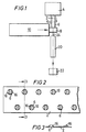
- a perforating machine 4 which forms two transversely spaced longitudinal rows of perforations or apertures 6 in the strip 2 adjacent to respective edges thereof.
- the steel base strip 2 is pierced in the perforating machine 4 in a manner such that peripheral projections or walls 16 extend upwardly therefrom, preferably angled towards each other.
- the particular configuration of the walls 15 dependson the nature of the piercing operation. performed by the perforating machine 4 so that it will be understood that the upwardly extending walls 16 can have configurations other than that shown in the figures.
- the perforated metallic base strip 2 is passed in a continuous manner through a cross-head extrusion/combining die 8 in a'direction parallel to the longitudinal axis of-the base strip 2.
- a suitable plastic material described below, is extruded by an extruder 10 in a direction perpendicular to the direction of travel of the metallic base strip 2 into the cross- head extrusion/combining die 8 so that the plastic material is extruded onto and through the perforations 6.
- the plastic material is directly extruded onto the.base strip 2 so that the heated plastic material flows into the apertures 6 under the projections or walls 16.
- the cross-head extrusion/combining die is designed and arranged so that the plastic material is extruded directly onto the metallic base strip 2 so as to form thereon two transversely spaced plastic strips 12 which define a central channel 14 extending longitudinally along the longitudinal axis of the base strip 2.
- the plastic material flows through the apertures 6 beneath the walls or projections 16 of the apertures or perforations 6.
- the walls 16 assist in retair ing the plastic strips 12 on the metallic base strip 2, such reten tion being even greater in the case where the walls 16 are angled upwardly towards each other.
- a matrix assembly 18 is formed which comprises the plastic strips 12 intimately bonded to the metallic base strip 2.
- the matrix assembly 18 is drawn from the cross-head extrusion/combining die 8 by a conventional caterpillar take-off mechanism 20 whereupon the matrix assembly 18 is wound onto a winding unit 22.
- the steel is preferably conditioned and degreased by means of a propane torch directed onto the strip upstream of the die 8.
- One of the important advantages of the present invention is that in view of the fact that the matrix assembly is formed by directly extruding plastic material onto the metallic base strip, various types of plastic can be used which will maximize wear resistance and, therefore, the anticipated life of the matrix assembly.
- plastic for example, polyvinylchloride, polycarbonate, N oryl and ABS are suitable for use in the manufacture of the matrix assembly in accordance with the invention.
- An adjustable roller 24 can be provided immediately downstream of the cross-head extrusion/combining die 8 to vary the angle at which the matrix assembly 18 exists from the die 8.
- Matrix assembly 18a differs from matrix assembly 18 described above in that instead of directly extruding plastic material onto the metallic base strip 2 so as form a pair of plastic strips 12, the plastic material is directly extruded onto the metallic base strip 2 in the form of a single strip, designated 30.
- the plastic strip 30 comprises a pair of ridges 32 integrally connected by thin plastic web 34. The ridges 32 are mutually spaced to form the channel 14 with the web 34 constituting the bottom of the channel 14.
- plastic strips 12 or plastic 30 are fully supported by the steel base strip 2.
- the plastic material is extruded in the form of a pair of plastic strips 12 which slope downwardly and outwardly and extend outwardly beyond the sides of the steel base strip 2.
- the base strip 2 is perforated in a manner similar to the embodi-. ments described above to facilitate retention of the plastic strips on the metallic base strip.
- the plastic material is directly extruded onto the metallic base strip 2 in a manner such that the base strip is encapsulated in the plastic strips 12. Because of the additional strength pro-. vided by such encapsulation, the metallic base strip 2 need not be perforated.
- the metallic base strip 2 of the embodiments of Figs. 4 and 6-8 has a width of 7 mm.
- the plastic strips 12 or plastic strip 30 also has a width of 7 mm.
- the plastic strips 12 have a width of 12 mm.
- the central channel 14 has a width of 1.5 mm.
- the matrix assembly constructed in accordance with the invention can be subsequently combined with a locater strip to facilitate the precise alignment of the central channel.14 with the associated creasing rule of a cutting and creasing press.
- U.S. Patent 3,919,924 discloses the construction of such a locater strip and one technique for associating the locater strip with the matrix assembly. The disclosure of this patent is hereby incorporated herein by reference.
- the method of manufacture in accordance with the invention provides an improved matrix assembly which eliminates any possibility of any space or gap existing between the plastic strip or strips and the steel base strip by virtue of the plastic being extruded directly onto the base strip as a primary process. This drastically reduces the possibility of the plastic strips eventually becoming loosened from the base strip by the constant up and down pressures existing in creasing presses. Additional design features can be easily added and sizes easily changes with substantially lower tooling costs. Various types of.plastic can be used to increase wear resistance and the anticipated life of the matrix assembly. Moreover, it has been found that it is possible to increase the production speed and to reduce production costs of the matrix assembly in accordance with the invention without reducing manufacturing tolerances.
Landscapes
- Engineering & Computer Science (AREA)
- Mechanical Engineering (AREA)
- Extrusion Moulding Of Plastics Or The Like (AREA)
- Diaphragms For Electromechanical Transducers (AREA)
- Superconductors And Manufacturing Methods Therefor (AREA)
- Glass Compositions (AREA)
- Shaping Of Tube Ends By Bending Or Straightening (AREA)
- Separation By Low-Temperature Treatments (AREA)
Priority Applications (1)
| Application Number | Priority Date | Filing Date | Title |
|---|---|---|---|
| AT83306398T ATE36983T1 (de) | 1982-10-22 | 1983-10-21 | Matrize. |
Applications Claiming Priority (2)
| Application Number | Priority Date | Filing Date | Title |
|---|---|---|---|
| GB8230299 | 1982-10-22 | ||
| GB8230299 | 1982-10-22 |
Publications (3)
| Publication Number | Publication Date |
|---|---|
| EP0107490A2 true EP0107490A2 (de) | 1984-05-02 |
| EP0107490A3 EP0107490A3 (en) | 1985-08-28 |
| EP0107490B1 EP0107490B1 (de) | 1988-09-07 |
Family
ID=10533798
Family Applications (1)
| Application Number | Title | Priority Date | Filing Date |
|---|---|---|---|
| EP83306398A Expired EP0107490B1 (de) | 1982-10-22 | 1983-10-21 | Matrize |
Country Status (4)
| Country | Link |
|---|---|
| EP (1) | EP0107490B1 (de) |
| AT (1) | ATE36983T1 (de) |
| DE (1) | DE3377902D1 (de) |
| GB (1) | GB2134841A (de) |
Cited By (2)
| Publication number | Priority date | Publication date | Assignee | Title |
|---|---|---|---|---|
| EP0775573A3 (de) * | 1995-11-21 | 1998-04-08 | Bayer Ag | Vorrichtung und Verfahren zur Herstellung von Kunststoff-/Metall-Verbundplatten |
| WO2004030877A1 (en) * | 2002-10-05 | 2004-04-15 | Man Mat Limited | Matrix assembly |
Families Citing this family (2)
| Publication number | Priority date | Publication date | Assignee | Title |
|---|---|---|---|---|
| US4722818A (en) * | 1984-03-20 | 1988-02-02 | The Standard Products Company | Method for making an elongated composite article |
| US4563141A (en) * | 1984-03-20 | 1986-01-07 | The Standard Products Company | Apparatus for making an elongated composite article |
Family Cites Families (7)
| Publication number | Priority date | Publication date | Assignee | Title |
|---|---|---|---|---|
| GB779278A (en) * | 1954-08-05 | 1957-07-17 | Pasche Heinz | Improvements in the production of hollow profiles from thermoplastic synthetic materials |
| DE1242355B (de) * | 1963-10-19 | 1967-06-15 | Schock & Co Gmbh | Verfahren zum Herstellen von mehrteiligen Schichtleisten |
| DE2151384A1 (de) * | 1971-10-15 | 1973-04-26 | Wupa Maschf Gmbh & Co | Bearbeitungswerkzeug mit bandstahlschnitt fuer stanzmaschinen fuer bogen aus papier, folie od. dgl |
| GB1481532A (en) * | 1973-07-06 | 1977-08-03 | Naka H | Apparatus for continuously producing a flexible non-skid strip |
| US3908498A (en) * | 1973-11-14 | 1975-09-30 | Mead Corp | Punching apparatus |
| GB1485361A (en) * | 1974-08-05 | 1977-09-08 | Goodwin P | Structures |
| BE893772A (fr) * | 1982-06-02 | 1983-01-06 | Hg Engineering Ltd | Appareil et procede pour fabriquer une bande renforcee |
-
1983
- 1983-10-21 EP EP83306398A patent/EP0107490B1/de not_active Expired
- 1983-10-21 GB GB08328182A patent/GB2134841A/en not_active Withdrawn
- 1983-10-21 AT AT83306398T patent/ATE36983T1/de active
- 1983-10-21 DE DE8383306398T patent/DE3377902D1/de not_active Expired
Cited By (2)
| Publication number | Priority date | Publication date | Assignee | Title |
|---|---|---|---|---|
| EP0775573A3 (de) * | 1995-11-21 | 1998-04-08 | Bayer Ag | Vorrichtung und Verfahren zur Herstellung von Kunststoff-/Metall-Verbundplatten |
| WO2004030877A1 (en) * | 2002-10-05 | 2004-04-15 | Man Mat Limited | Matrix assembly |
Also Published As
| Publication number | Publication date |
|---|---|
| EP0107490A3 (en) | 1985-08-28 |
| GB8328182D0 (en) | 1983-11-23 |
| ATE36983T1 (de) | 1988-09-15 |
| GB2134841A (en) | 1984-08-22 |
| DE3377902D1 (en) | 1988-10-13 |
| EP0107490B1 (de) | 1988-09-07 |
Similar Documents
| Publication | Publication Date | Title |
|---|---|---|
| US4214024A (en) | Composite label web and method of making same | |
| KR950031456A (ko) | 열가소성 물질로부터 스트립 생성물을 성형하는 방법 | |
| EP0549515B1 (de) | Verfahren und Vorrichtung zur Herstellung eines Tropfbewässerungsrohres | |
| US2899347A (en) | Method of making bag closure | |
| EP0182139B1 (de) | Schale zur Aufnahme von Nahrungsmitteln, sowie Verfahren und Vorrichtung zu deren Herstellung | |
| EP0270337B1 (de) | Profilstück und Herstellungsverfahren | |
| US4851067A (en) | Method for producing a weather strip for an automobile | |
| US20030101851A1 (en) | Composite blade | |
| CA2054971C (en) | Process and an apparatus for the production of food products by coextrusion cooking | |
| EP0498764B1 (de) | Vorrichtung zur Herstellung von Rohrkörpern | |
| DE2954233C2 (de) | ||
| US20040022890A1 (en) | Arrangement for making a belt made of plasticatable material | |
| US4262939A (en) | Slide chart manufacture | |
| US4659302A (en) | Deckle structure for a film extrusion die | |
| EP0107490A2 (de) | Matrize | |
| EP1484159B1 (de) | Extrusionsdüse und verfahren zur regelung des flusses eines extrudates | |
| CA2462033A1 (en) | Method of forming a continuous belt for a belt-type separator device | |
| KR930007636A (ko) | 복합시이트 재료의 제조방법 | |
| US6454555B1 (en) | Apparatus for making an annular friction liner | |
| EP0038559A2 (de) | Verfahren zur Herstellung einer verschleissfesten Folie und Vorrichtung zu deren Herstellung | |
| EP0340211B1 (de) | Verfahren zum Herstellen von Laufflächenbelägen für Skier, Ski-Lauf-Flächenbauteil mit einem so hergestellten Laufflächenbelag sowie Ski mit einem solchem Laufflächenbelag oder Laufflächenbauteil | |
| CN1014877B (zh) | 制造木屑板和类似板材的生产方法及装置 | |
| EP0955148A1 (de) | Strangpressen mit einem Drahtkern mit einer variablen neutralen Achse | |
| US4146418A (en) | Process for labelling deep-drawn cups | |
| EP1418145B1 (de) | Verfahren und Vorrichtung zum Herstellen von Falt-Coupons |
Legal Events
| Date | Code | Title | Description |
|---|---|---|---|
| PUAI | Public reference made under article 153(3) epc to a published international application that has entered the european phase |
Free format text: ORIGINAL CODE: 0009012 |
|
| AK | Designated contracting states |
Designated state(s): AT BE CH DE FR GB IT LI LU NL SE |
|
| PUAL | Search report despatched |
Free format text: ORIGINAL CODE: 0009013 |
|
| AK | Designated contracting states |
Designated state(s): AT BE CH DE FR GB IT LI LU NL SE |
|
| 17P | Request for examination filed |
Effective date: 19860217 |
|
| 17Q | First examination report despatched |
Effective date: 19870126 |
|
| GRAA | (expected) grant |
Free format text: ORIGINAL CODE: 0009210 |
|
| AK | Designated contracting states |
Kind code of ref document: B1 Designated state(s): AT BE CH DE FR GB IT LI LU NL SE |
|
| PG25 | Lapsed in a contracting state [announced via postgrant information from national office to epo] |
Ref country code: SE Effective date: 19880907 Ref country code: NL Effective date: 19880907 Ref country code: LI Effective date: 19880907 Ref country code: CH Effective date: 19880907 Ref country code: BE Effective date: 19880907 Ref country code: AT Effective date: 19880907 |
|
| REF | Corresponds to: |
Ref document number: 36983 Country of ref document: AT Date of ref document: 19880915 Kind code of ref document: T |
|
| REF | Corresponds to: |
Ref document number: 3377902 Country of ref document: DE Date of ref document: 19881013 |
|
| ITF | It: translation for a ep patent filed | ||
| ET | Fr: translation filed | ||
| PG25 | Lapsed in a contracting state [announced via postgrant information from national office to epo] |
Ref country code: LU Free format text: LAPSE BECAUSE OF NON-PAYMENT OF DUE FEES Effective date: 19881031 |
|
| REG | Reference to a national code |
Ref country code: CH Ref legal event code: PL |
|
| NLV1 | Nl: lapsed or annulled due to failure to fulfill the requirements of art. 29p and 29m of the patents act | ||
| PLBE | No opposition filed within time limit |
Free format text: ORIGINAL CODE: 0009261 |
|
| STAA | Information on the status of an ep patent application or granted ep patent |
Free format text: STATUS: NO OPPOSITION FILED WITHIN TIME LIMIT |
|
| 26N | No opposition filed | ||
| PGFP | Annual fee paid to national office [announced via postgrant information from national office to epo] |
Ref country code: FR Payment date: 19901024 Year of fee payment: 8 |
|
| ITTA | It: last paid annual fee | ||
| GBPC | Gb: european patent ceased through non-payment of renewal fee | ||
| PG25 | Lapsed in a contracting state [announced via postgrant information from national office to epo] |
Ref country code: FR Effective date: 19920630 |
|
| REG | Reference to a national code |
Ref country code: FR Ref legal event code: ST |
|
| REG | Reference to a national code |
Ref country code: GB Ref legal event code: 728C |
|
| REG | Reference to a national code |
Ref country code: GB Ref legal event code: 728A |
|
| PGFP | Annual fee paid to national office [announced via postgrant information from national office to epo] |
Ref country code: GB Payment date: 20011024 Year of fee payment: 19 |
|
| PGFP | Annual fee paid to national office [announced via postgrant information from national office to epo] |
Ref country code: DE Payment date: 20011105 Year of fee payment: 19 |
|
| REG | Reference to a national code |
Ref country code: GB Ref legal event code: IF02 |
|
| PG25 | Lapsed in a contracting state [announced via postgrant information from national office to epo] |
Ref country code: GB Free format text: LAPSE BECAUSE OF NON-PAYMENT OF DUE FEES Effective date: 20021021 |
|
| PG25 | Lapsed in a contracting state [announced via postgrant information from national office to epo] |
Ref country code: DE Free format text: LAPSE BECAUSE OF NON-PAYMENT OF DUE FEES Effective date: 20030501 |
|
| GBPC | Gb: european patent ceased through non-payment of renewal fee |
Effective date: 20021021 |