EP0106686A2 - Abwechselnd texturiertes Garn - Google Patents
Abwechselnd texturiertes Garn Download PDFInfo
- Publication number
- EP0106686A2 EP0106686A2 EP83306250A EP83306250A EP0106686A2 EP 0106686 A2 EP0106686 A2 EP 0106686A2 EP 83306250 A EP83306250 A EP 83306250A EP 83306250 A EP83306250 A EP 83306250A EP 0106686 A2 EP0106686 A2 EP 0106686A2
- Authority
- EP
- European Patent Office
- Prior art keywords
- yarn
- false
- electromagnet
- creel
- tension
- Prior art date
- Legal status (The legal status is an assumption and is not a legal conclusion. Google has not performed a legal analysis and makes no representation as to the accuracy of the status listed.)
- Granted
Links
- 238000000034 method Methods 0.000 claims description 7
- 239000004744 fabric Substances 0.000 abstract description 2
- 238000004519 manufacturing process Methods 0.000 abstract description 2
- 230000000007 visual effect Effects 0.000 abstract description 2
- 230000008602 contraction Effects 0.000 description 6
- 239000000463 material Substances 0.000 description 4
- 239000002932 luster Substances 0.000 description 3
- 229920000728 polyester Polymers 0.000 description 3
- 230000004048 modification Effects 0.000 description 2
- 238000012986 modification Methods 0.000 description 2
- CWYNVVGOOAEACU-UHFFFAOYSA-N Fe2+ Chemical compound [Fe+2] CWYNVVGOOAEACU-UHFFFAOYSA-N 0.000 description 1
- 239000004809 Teflon Substances 0.000 description 1
- 229920006362 Teflon® Polymers 0.000 description 1
- 238000004140 cleaning Methods 0.000 description 1
- 238000010586 diagram Methods 0.000 description 1
- 238000002360 preparation method Methods 0.000 description 1
- 238000000926 separation method Methods 0.000 description 1
Images

Classifications
-
- D—TEXTILES; PAPER
- D02—YARNS; MECHANICAL FINISHING OF YARNS OR ROPES; WARPING OR BEAMING
- D02G—CRIMPING OR CURLING FIBRES, FILAMENTS, THREADS, OR YARNS; YARNS OR THREADS
- D02G1/00—Producing crimped or curled fibres, filaments, yarns, or threads, giving them latent characteristics
- D02G1/02—Producing crimped or curled fibres, filaments, yarns, or threads, giving them latent characteristics by twisting, fixing the twist and backtwisting, i.e. by imparting false twist
- D02G1/0206—Producing crimped or curled fibres, filaments, yarns, or threads, giving them latent characteristics by twisting, fixing the twist and backtwisting, i.e. by imparting false twist by false-twisting
- D02G1/0266—Producing crimped or curled fibres, filaments, yarns, or threads, giving them latent characteristics by twisting, fixing the twist and backtwisting, i.e. by imparting false twist by false-twisting false-twisting machines
-
- B—PERFORMING OPERATIONS; TRANSPORTING
- B65—CONVEYING; PACKING; STORING; HANDLING THIN OR FILAMENTARY MATERIAL
- B65H—HANDLING THIN OR FILAMENTARY MATERIAL, e.g. SHEETS, WEBS, CABLES
- B65H59/00—Adjusting or controlling tension in filamentary material, e.g. for preventing snarling; Applications of tension indicators
- B65H59/10—Adjusting or controlling tension in filamentary material, e.g. for preventing snarling; Applications of tension indicators by devices acting on running material and not associated with supply or take-up devices
- B65H59/20—Co-operating surfaces mounted for relative movement
- B65H59/22—Co-operating surfaces mounted for relative movement and arranged to apply pressure to material
- B65H59/225—Tension discs
-
- D—TEXTILES; PAPER
- D02—YARNS; MECHANICAL FINISHING OF YARNS OR ROPES; WARPING OR BEAMING
- D02G—CRIMPING OR CURLING FIBRES, FILAMENTS, THREADS, OR YARNS; YARNS OR THREADS
- D02G1/00—Producing crimped or curled fibres, filaments, yarns, or threads, giving them latent characteristics
- D02G1/02—Producing crimped or curled fibres, filaments, yarns, or threads, giving them latent characteristics by twisting, fixing the twist and backtwisting, i.e. by imparting false twist
- D02G1/0206—Producing crimped or curled fibres, filaments, yarns, or threads, giving them latent characteristics by twisting, fixing the twist and backtwisting, i.e. by imparting false twist by false-twisting
- D02G1/024—Producing crimped or curled fibres, filaments, yarns, or threads, giving them latent characteristics by twisting, fixing the twist and backtwisting, i.e. by imparting false twist by false-twisting with provision for imparting irregular effects to the yarn
-
- B—PERFORMING OPERATIONS; TRANSPORTING
- B65—CONVEYING; PACKING; STORING; HANDLING THIN OR FILAMENTARY MATERIAL
- B65H—HANDLING THIN OR FILAMENTARY MATERIAL, e.g. SHEETS, WEBS, CABLES
- B65H2555/00—Actuating means
- B65H2555/10—Actuating means linear
- B65H2555/13—Actuating means linear magnetic, e.g. induction motors
-
- B—PERFORMING OPERATIONS; TRANSPORTING
- B65—CONVEYING; PACKING; STORING; HANDLING THIN OR FILAMENTARY MATERIAL
- B65H—HANDLING THIN OR FILAMENTARY MATERIAL, e.g. SHEETS, WEBS, CABLES
- B65H2701/00—Handled material; Storage means
- B65H2701/30—Handled filamentary material
- B65H2701/31—Textiles threads or artificial strands of filaments
Definitions
- This invention relates generally to the employment of an electromagnetically actuated disc tension control to intermittently grasp and release a continuous filament synthetic yarn which is being processed downstream of the tension control.
- the system is directed to a method to produce a specially textured yarn by intermittently varying the draw of a continuous filament partially oriented, synthetic, multifilament yarn such as polyester.
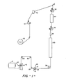
- the multifilament yarn 10 is supplied from a supply package 12 to the false twist device 14 by the feed roll device 16.
- the yarn 10 from the package 12 successively, in its travel to the feed roll device 16, passes through the balloon control apparatus 18, over the guide members 20, 22 and 24 through the electro-magnetically controlled tension disc apparatus 26 and under the guide member 28 through the primary heater 30 and false twist device 14 to the feed roll device 16.
- the yarn 10 is intermittently and randomly drawn in the primary heater 30 by the intermittent hold back action of the disc tension apparatus 26.
- the discs 32 and 34 are intermittently and randomly drawn together and released on the yarn 10 by the action of the electromagnet 36 controlled by the varying voltage supplied thereto by a suitable voltage source which is varied by the action of a random signal generator.
- the textured yarn passes through the secondary heater 37 with very little overfeed since the speed of the feed roll device 38 is substantially the same as the feed roll device 16 and the crimp in the yarn is allowed to set.
- the secondary heater can be turned on at an appropriate temperature or off or by-passed and the overfeed varied from high to very little.
- the feed roll device 38 is driven at a higher speed than the feed roll device 44 to overfeed the textured yarn through the air jet entangling device 40 to commingle and entangle the individual filaments of the textured yarn. From the feed roll device 38 the entangled, textured yarn is slightly overfed to the yarn take-up package 42 by the feed roll device 44.
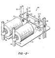
- a creel unit designated 46 in Figure 2
- the creel unit 46 supports a plurality of packages 12 for a plurality of false twist spindle positions and is slid in and out of position relative to a multiple spindle false twisting machine.
- a partial creel is shown supporting a pair of supply packages held on creel pins supported by creel pin support members 48 that are connected to the creel.
- a horizontal separation plate 50 Also connected to the creel is a horizontal separation plate 50 through which the yarn guide supports 52 project.
- a yarn guide 54 for each yarn package is connected thereto to guide the yarn 10 from the package 12 towards the guide member 20.
- a channel beam 56 between which is connected the balloon control apparatus or bar 18.
- the balloon of yarn from the creel is unusually erratic and violent due to the alternating take-off velocity and is therefore prone to entanglement if not controlled.
- the bar 18 prevents yarn 10 from the package 12 from forming a full balloon and getting entangled in and around various elements of the creel such as yarn guides 54.
- a second bar 18 is shown which is used for the same purpose for the yarn packages (not shown) on the opposite side of the creel unit 46.
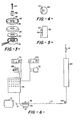
- Figures 3-5 show the electromagnetically controlled tension disc apparatus 26 in detail.
- the apparatus 26 basically consists of the electromagnet 36, the spring biasing member 60 of Teflon or other suitable material, the tension discs 32 and 34, the disc post 62 and the screw 63 to maintain the aforementioned element in operative relationship.
- the disc 32 is made from a magnetically attractable material such as a ferrous material while the disc 34 is manufactured from a non-magnetically attractable material.
- the post 62 has a slot 64 therein which is off set from the centerline of the post. Also for reasons hereinafter explained, it is desired to supply random, intermittent pulses of low and high D.C. voltage with a superimposed A.C.
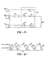
- the voltage to the electromagnet 36 is supplied from a control box 65 which receives voltage from an A.C.power supply 66, a high voltage D.C. power supply 68 and a low voltage D.C. power supply 70.
- a random signal generator 72 Connected between the high voltage D.C. source 68 and the control box 65 is a random signal generator 72 of the type disclosed in U. S. Patent Number 4,160,359 which intermittently and randomly interrupts the voltage from the high voltage D.C. source to the control box 65.
- each circuit to the electromagnet 36 Located in each circuit to the electromagnet 36 is a diode 74 which only allows current to flow in one direction towards the electromagnet 36.
- a diode 74 Schematically represented in the high and low voltage D.C. circuit is an adjust switch or variable resistor 76 to adjust the D.C. voltage in the respective circuit.
- the A.C. voltage from the source 66 supplies A.C. voltage continuously while the high D.C. voltage from the source 68 is interrupted randomly and continuously by the random signal generator 72.
- this provides periods of high voltage 78 and low voltage 80 for different durations of time, as well as peaks 82 at times when the high voltage D.C. current is not being supplied and the A.C. current is at its positive peak on its cycle.
- the various lengths of the high voltage peak 78 represent periods when the yarn 10 is being held tightly between the discs 32 and 34 while the peaks 82 and the low voltage periods 80 represent periods when the voltage is low and the discs 32 and 34 tend to release the grip on the yarn 10 and vibrate as the yarn passes therethrough.
- the spring biasing member 60 causes the discs to be urged upward and allows the frictional resistance between the discs 32 and 34 and between the disc 34 and the electromagnet 36 to be reduced so that the torque exerted by the yarn passing through the slot 64 of the post 62 will cause them to rotate more efficiently to provide the self-cleaning action.
- the vibration of the discs allows the discs to be rotated more easily so that the yarn passing through will subsequently clean out the finish deposited between the discs by the yarn.
- FIGs 9 and 10 an alternate scheme is shown to enhance the rotation of the discs 32 and 34.
- elements therein whichare the same in Figures 1-8 are indicated by the same reference number.
- the basic modification shown in Figures 9 and 10. is the inclusion of a timer 100 in the low voltage D.C. circuit to momentarily cut-off the current flow in the D.C. circuit to the electromagnet 36 to allow the A.C. voltage to peak as indicated in Figure 10. It is understood that the current in the A.C. circuit is flowing continuously in order to obtain the result shown in Figure 10.
- the timer 100 has the low voltage D.C. circuit open and the random signal generator 72 has the high voltage DrC. circuit open
- only half-wave rectified A.C. voltage is applied to the coil as shown in Figure 10. This will momentarily upset the tension of the yarn, but enhances the rotation of the discs 32 and 34.
- the wall 84 defining one portion of the slot 64 can be eliminated and replaced by an upstanding guide member, not shown, which will serve to confine the yarn path to a path offset from the centerline of the post 62.
- the spring biasing member 60 is of a diameter greater than the inner, internal diameter 85 and less than the inner, external diameter 86 of the lower tension disc 34 so that it is curved downward at its extremities when the discs 32 and 34 are pulled towards the electromagnet 36. Conversely, when the voltage to the electromagnet is reduced, the upward force exerted due to the bias of the member 60 urges the discs upward.
- the tension discs 32 and 34 it is desired to cause the tension discs 32 and 34 to rotate in order to dissipate the finish deposited therebetween by the yarn 10.
- the discs 32 and 34 are free to rotate on the post 62.
- the slot 64 is located off center of the centerline of the post so that the yarn passing between the discs 32 and 34 will exert a torque thereon.
- yarn 10 since yarn 10 is located in the slot 64 between the discs 32 and 34, the yarn cannot jump out from between the discs and have to be rethreaded. Further, such location of the yarn in the slot prevents uncontrolled texturing and lessens the tendency for yarn breaks.
- Two ends of a 240 denier, 68 filament DuPont 56T polyester yarn were processed as described above and entangled or interlaced in the air jet 40 to provide a 2/150/68 yarn with an actual denier of 321.
- the elongation was 51% with a crimp contraction of 1%.
- the operating conditions were as follows:
- the yarn thus produced has a very low crimp contraction with high luster and intermittent character.
- Two ends of a 220 denier, 54 filament DuPont 693T polyester yarn were processed and entangled in the air jet 40 to provide a 2/150/54 yarn with an actual diameter of 328 denier.
- the elongation was 48% with a crimp contraction of 1.8%.
- the operating conditions were as follows:
- the yarn produced has a low crimp contraction with very high luster and intermittent character.
- the described apparatus and method provides a randomly, intermittently textured, continuous multifilament synthetic yarn which along its length has variable molecular orientation, bulk, torque, twist and shrinkage.
- the produced yarn has a low crimp contraction and a high luster.
- This yarn is especially useful in the fabrication of a velvet-type upholstery fabric and provides unique visual effects due to its variable dye affinity.
Landscapes
- Engineering & Computer Science (AREA)
- Mechanical Engineering (AREA)
- Textile Engineering (AREA)
- Yarns And Mechanical Finishing Of Yarns Or Ropes (AREA)
Priority Applications (1)
| Application Number | Priority Date | Filing Date | Title |
|---|---|---|---|
| AT83306250T ATE48854T1 (de) | 1982-10-18 | 1983-10-14 | Abwechselnd texturiertes garn. |
Applications Claiming Priority (18)
| Application Number | Priority Date | Filing Date | Title |
|---|---|---|---|
| US434900 | 1982-10-18 | ||
| US434898 | 1982-10-18 | ||
| US434899 | 1982-10-18 | ||
| US06/434,899 US4454710A (en) | 1982-10-18 | 1982-10-18 | Balloon control for yarn texturing machine |
| US435052 | 1982-10-18 | ||
| US434909 | 1982-10-18 | ||
| US06/434,909 US4449354A (en) | 1982-10-18 | 1982-10-18 | Disc type yarn tension control |
| US06/434,898 US4446690A (en) | 1982-10-18 | 1982-10-18 | Bar balloon control |
| US06/434,900 US4462557A (en) | 1982-10-18 | 1982-10-18 | Spring biased electromagnetically controlled tension control |
| US435053 | 1982-10-18 | ||
| US06/435,052 US4457129A (en) | 1982-10-18 | 1982-10-18 | Slotted disc type yarn tension control |
| US06/435,053 US4449355A (en) | 1982-10-18 | 1982-10-18 | A.C.-D.C. Slotted type yarn tension control |
| US06/440,497 US4446691A (en) | 1982-11-10 | 1982-11-10 | High A.C.-D.C. yarn tension control |
| US440497 | 1982-11-10 | ||
| US06/440,498 US4449356A (en) | 1982-11-10 | 1982-11-10 | Continuous A.C. tension control |
| US440498 | 1982-11-10 | ||
| US06/468,469 US4478036A (en) | 1983-02-22 | 1983-02-22 | Method, apparatus and intermittently textured yarn |
| US468469 | 1983-02-22 |
Publications (3)
| Publication Number | Publication Date |
|---|---|
| EP0106686A2 true EP0106686A2 (de) | 1984-04-25 |
| EP0106686A3 EP0106686A3 (en) | 1986-01-22 |
| EP0106686B1 EP0106686B1 (de) | 1989-12-20 |
Family
ID=27578839
Family Applications (1)
| Application Number | Title | Priority Date | Filing Date |
|---|---|---|---|
| EP19830306250 Expired EP0106686B1 (de) | 1982-10-18 | 1983-10-14 | Abwechselnd texturiertes Garn |
Country Status (2)
| Country | Link |
|---|---|
| EP (1) | EP0106686B1 (de) |
| DE (1) | DE3380991D1 (de) |
Family Cites Families (7)
| Publication number | Priority date | Publication date | Assignee | Title |
|---|---|---|---|---|
| US3100091A (en) * | 1961-03-20 | 1963-08-06 | Lindley & Company Inc | Yarn tensioning device |
| US3350867A (en) * | 1965-08-24 | 1967-11-07 | Burlington Industries Inc | Process and apparatus for making a novelty yarn |
| GB1362178A (en) * | 1971-11-24 | 1974-07-30 | Courtaulds Ltd | Crimped filaments of varying denier |
| US3911655A (en) * | 1972-01-11 | 1975-10-14 | Burlington Industries Inc | Process and apparatus for making textured yarn |
| US3797775A (en) * | 1973-02-01 | 1974-03-19 | E White | Strand tension control |
| DE2411074A1 (de) * | 1974-03-08 | 1975-09-18 | Akzo Gmbh | Verfahren und vorrichtung zur herstellung eines abwechselnd dicke und duenne stellen aufweisenden effektgarns |
| US4345424A (en) * | 1980-06-23 | 1982-08-24 | Akzona Incorporated | Textured novelty yarn and process |
-
1983
- 1983-10-14 EP EP19830306250 patent/EP0106686B1/de not_active Expired
- 1983-10-14 DE DE8383306250T patent/DE3380991D1/de not_active Expired - Fee Related
Also Published As
| Publication number | Publication date |
|---|---|
| EP0106686B1 (de) | 1989-12-20 |
| DE3380991D1 (de) | 1990-01-25 |
| EP0106686A3 (en) | 1986-01-22 |
Similar Documents
| Publication | Publication Date | Title |
|---|---|---|
| US2852906A (en) | Method and apparatus for producing bulky continuous filament yarn | |
| US4080777A (en) | Novelty yarns | |
| US3041812A (en) | Process and apparatus for making novelty yarn | |
| US3017737A (en) | Method and apparatus for producing bulky continuous filament yarn | |
| US4736578A (en) | Method for forming a slub yarn | |
| US3262177A (en) | Apparatus for producing novelty bulked yarn | |
| US3253396A (en) | Method and apparatus for making textured yarn and product | |
| US5307616A (en) | Method to manufacture a slub yarn | |
| US4345425A (en) | Process for making bulky textured multifilament yarn | |
| US4184316A (en) | Production of novelty yarns | |
| US4462557A (en) | Spring biased electromagnetically controlled tension control | |
| US4351148A (en) | False twisted slub yarn | |
| US4368612A (en) | Apparatus for forming false twisted slubyarn | |
| US4305245A (en) | Method of forming false twisted slub yarn | |
| US4449355A (en) | A.C.-D.C. Slotted type yarn tension control | |
| US4532760A (en) | D. C. Yarn tension control | |
| US4449354A (en) | Disc type yarn tension control | |
| US4457129A (en) | Slotted disc type yarn tension control | |
| US4449356A (en) | Continuous A.C. tension control | |
| EP0106686B1 (de) | Abwechselnd texturiertes Garn | |
| US4446691A (en) | High A.C.-D.C. yarn tension control | |
| US3076307A (en) | Novelty core constructed yarn | |
| US4250701A (en) | Apparatus and method for making loop chenille type yarn | |
| JP2003054838A (ja) | 特殊糸を製造するための装置およびその使用 | |
| IE55949B1 (en) | Intermittently textured yarn |
Legal Events
| Date | Code | Title | Description |
|---|---|---|---|
| PUAI | Public reference made under article 153(3) epc to a published international application that has entered the european phase |
Free format text: ORIGINAL CODE: 0009012 |
|
| AK | Designated contracting states |
Designated state(s): AT BE CH DE FR GB IT LI LU NL SE |
|
| PUAL | Search report despatched |
Free format text: ORIGINAL CODE: 0009013 |
|
| AK | Designated contracting states |
Designated state(s): AT BE CH DE FR GB IT LI LU NL SE |
|
| 17P | Request for examination filed |
Effective date: 19860711 |
|
| 17Q | First examination report despatched |
Effective date: 19880219 |
|
| GRAA | (expected) grant |
Free format text: ORIGINAL CODE: 0009210 |
|
| ITF | It: translation for a ep patent filed | ||
| AK | Designated contracting states |
Kind code of ref document: B1 Designated state(s): AT BE CH DE FR GB IT LI LU NL SE |
|
| REF | Corresponds to: |
Ref document number: 48854 Country of ref document: AT Date of ref document: 19900115 Kind code of ref document: T |
|
| ET | Fr: translation filed | ||
| REF | Corresponds to: |
Ref document number: 3380991 Country of ref document: DE Date of ref document: 19900125 |
|
| PLBE | No opposition filed within time limit |
Free format text: ORIGINAL CODE: 0009261 |
|
| STAA | Information on the status of an ep patent application or granted ep patent |
Free format text: STATUS: NO OPPOSITION FILED WITHIN TIME LIMIT |
|
| 26N | No opposition filed | ||
| ITTA | It: last paid annual fee | ||
| EPTA | Lu: last paid annual fee | ||
| EAL | Se: european patent in force in sweden |
Ref document number: 83306250.8 |
|
| PGFP | Annual fee paid to national office [announced via postgrant information from national office to epo] |
Ref country code: LU Payment date: 20001011 Year of fee payment: 18 |
|
| PGFP | Annual fee paid to national office [announced via postgrant information from national office to epo] |
Ref country code: FR Payment date: 20010925 Year of fee payment: 19 |
|
| PGFP | Annual fee paid to national office [announced via postgrant information from national office to epo] |
Ref country code: CH Payment date: 20011001 Year of fee payment: 19 |
|
| PGFP | Annual fee paid to national office [announced via postgrant information from national office to epo] |
Ref country code: SE Payment date: 20011002 Year of fee payment: 19 |
|
| PGFP | Annual fee paid to national office [announced via postgrant information from national office to epo] |
Ref country code: AT Payment date: 20011005 Year of fee payment: 19 |
|
| PGFP | Annual fee paid to national office [announced via postgrant information from national office to epo] |
Ref country code: NL Payment date: 20011008 Year of fee payment: 19 Ref country code: GB Payment date: 20011008 Year of fee payment: 19 |
|
| PGFP | Annual fee paid to national office [announced via postgrant information from national office to epo] |
Ref country code: BE Payment date: 20011010 Year of fee payment: 19 |
|
| PGFP | Annual fee paid to national office [announced via postgrant information from national office to epo] |
Ref country code: DE Payment date: 20011230 Year of fee payment: 19 |
|
| REG | Reference to a national code |
Ref country code: GB Ref legal event code: IF02 |
|
| PG25 | Lapsed in a contracting state [announced via postgrant information from national office to epo] |
Ref country code: LU Free format text: LAPSE BECAUSE OF NON-PAYMENT OF DUE FEES Effective date: 20021014 Ref country code: GB Free format text: LAPSE BECAUSE OF NON-PAYMENT OF DUE FEES Effective date: 20021014 Ref country code: AT Free format text: LAPSE BECAUSE OF NON-PAYMENT OF DUE FEES Effective date: 20021014 |
|
| PG25 | Lapsed in a contracting state [announced via postgrant information from national office to epo] |
Ref country code: SE Free format text: LAPSE BECAUSE OF NON-PAYMENT OF DUE FEES Effective date: 20021015 |
|
| PG25 | Lapsed in a contracting state [announced via postgrant information from national office to epo] |
Ref country code: LI Free format text: LAPSE BECAUSE OF NON-PAYMENT OF DUE FEES Effective date: 20021031 Ref country code: CH Free format text: LAPSE BECAUSE OF NON-PAYMENT OF DUE FEES Effective date: 20021031 Ref country code: BE Free format text: LAPSE BECAUSE OF NON-PAYMENT OF DUE FEES Effective date: 20021031 |
|
| BERE | Be: lapsed |
Owner name: *MILLIKEN RESEARCH CORP. Effective date: 20021031 |
|
| PG25 | Lapsed in a contracting state [announced via postgrant information from national office to epo] |
Ref country code: NL Free format text: LAPSE BECAUSE OF NON-PAYMENT OF DUE FEES Effective date: 20030501 Ref country code: DE Free format text: LAPSE BECAUSE OF NON-PAYMENT OF DUE FEES Effective date: 20030501 |
|
| EUG | Se: european patent has lapsed | ||
| GBPC | Gb: european patent ceased through non-payment of renewal fee |
Effective date: 20021014 |
|
| REG | Reference to a national code |
Ref country code: CH Ref legal event code: PL |
|
| PG25 | Lapsed in a contracting state [announced via postgrant information from national office to epo] |
Ref country code: FR Free format text: LAPSE BECAUSE OF NON-PAYMENT OF DUE FEES Effective date: 20030630 |
|
| NLV4 | Nl: lapsed or anulled due to non-payment of the annual fee |
Effective date: 20030501 |
|
| REG | Reference to a national code |
Ref country code: FR Ref legal event code: ST |