EP0106019A2 - Maschine zum automatischen Stapeln von Plattenpaketen mit unterschiedlichen Grössen auf betreffende Hebeplattformen - Google Patents
Maschine zum automatischen Stapeln von Plattenpaketen mit unterschiedlichen Grössen auf betreffende Hebeplattformen Download PDFInfo
- Publication number
- EP0106019A2 EP0106019A2 EP83106003A EP83106003A EP0106019A2 EP 0106019 A2 EP0106019 A2 EP 0106019A2 EP 83106003 A EP83106003 A EP 83106003A EP 83106003 A EP83106003 A EP 83106003A EP 0106019 A2 EP0106019 A2 EP 0106019A2
- Authority
- EP
- European Patent Office
- Prior art keywords
- panels
- packs
- carriage
- fact
- machine according
- Prior art date
- Legal status (The legal status is an assumption and is not a legal conclusion. Google has not performed a legal analysis and makes no representation as to the accuracy of the status listed.)
- Granted
Links
Images


Classifications
-
- B—PERFORMING OPERATIONS; TRANSPORTING
- B65—CONVEYING; PACKING; STORING; HANDLING THIN OR FILAMENTARY MATERIAL
- B65G—TRANSPORT OR STORAGE DEVICES, e.g. CONVEYORS FOR LOADING OR TIPPING, SHOP CONVEYOR SYSTEMS OR PNEUMATIC TUBE CONVEYORS
- B65G37/00—Combinations of mechanical conveyors of the same kind, or of different kinds, of interest apart from their application in particular machines or use in particular manufacturing processes
- B65G37/02—Flow-sheets for conveyor combinations in warehouses, magazines or workshops
-
- B—PERFORMING OPERATIONS; TRANSPORTING
- B23—MACHINE TOOLS; METAL-WORKING NOT OTHERWISE PROVIDED FOR
- B23D—PLANING; SLOTTING; SHEARING; BROACHING; SAWING; FILING; SCRAPING; LIKE OPERATIONS FOR WORKING METAL BY REMOVING MATERIAL, NOT OTHERWISE PROVIDED FOR
- B23D47/00—Sawing machines or sawing devices working with circular saw blades, characterised only by constructional features of particular parts
- B23D47/04—Sawing machines or sawing devices working with circular saw blades, characterised only by constructional features of particular parts of devices for feeding, positioning, clamping, or rotating work
- B23D47/042—Sawing machines or sawing devices working with circular saw blades, characterised only by constructional features of particular parts of devices for feeding, positioning, clamping, or rotating work for conveying work to, or discharging work from, the machine
-
- B—PERFORMING OPERATIONS; TRANSPORTING
- B27—WORKING OR PRESERVING WOOD OR SIMILAR MATERIAL; NAILING OR STAPLING MACHINES IN GENERAL
- B27B—SAWS FOR WOOD OR SIMILAR MATERIAL; COMPONENTS OR ACCESSORIES THEREFOR
- B27B31/00—Arrangements for conveying, loading, turning, adjusting, or discharging the log or timber, specially designed for saw mills or sawing machines
- B27B31/003—Arrangements for conveying, loading, turning, adjusting, or discharging the log or timber, specially designed for saw mills or sawing machines with rollers
-
- B—PERFORMING OPERATIONS; TRANSPORTING
- B27—WORKING OR PRESERVING WOOD OR SIMILAR MATERIAL; NAILING OR STAPLING MACHINES IN GENERAL
- B27B—SAWS FOR WOOD OR SIMILAR MATERIAL; COMPONENTS OR ACCESSORIES THEREFOR
- B27B31/00—Arrangements for conveying, loading, turning, adjusting, or discharging the log or timber, specially designed for saw mills or sawing machines
- B27B31/08—Discharging equipment
-
- B—PERFORMING OPERATIONS; TRANSPORTING
- B65—CONVEYING; PACKING; STORING; HANDLING THIN OR FILAMENTARY MATERIAL
- B65G—TRANSPORT OR STORAGE DEVICES, e.g. CONVEYORS FOR LOADING OR TIPPING, SHOP CONVEYOR SYSTEMS OR PNEUMATIC TUBE CONVEYORS
- B65G57/00—Stacking of articles
Definitions
- This invention relates to a machine for stacking automatically, on respective lifting platforms, panels or packs of panels of different sizes coming in any succession from a dividing machine or any other manufacturing or working machine.
- The ain object of this invention is to enable the formation of a stack of panels of the same size on each lifting platform, so as to simplify the successive discharge and sorting of said stacks of panels, which is particularly important, for example, when said stacks are then to be strapped.
- Z indicates the last cutting of a composite dividing machine wherefrom packs P of side-by-side panels will be discharged cyclically to be stacked automatically onto respective lifting platforms T of suitable dimensions, so that packs of the same size will be stacked on each platform.
- the packs of panels arriving cyclically downstream of the cutting line Z are transferred by a device, symbolically shown by the arrow A, to a station B.
- the packs of panels to be stacked on the lifting platform T are, if desired, rotated together by 90° and are then transferred onto a composite transport line C whereon, therefore, the packs can be still disposed side by side if they have been rotated as above, or they can be disposed after each other.
- the platforms T are arranged in linear groups formed by a suitable number on rows at right angles to the transport line C.
- operating units D and D' are arranged to stop the packs of panels and transfer them, one by one and suitably spaced from each other, to sorting means, symbolically shown by the arrows E, E', which will stack said packs on the desired platform or platforms T.
- the stacks P' of panels formed on the lifting platforms T can be discharged from the latter and either arranged side by side on successive dwell stations G-G' or transferred immediately onto powered roller assemblies H-H' which, for example, will feed said stacks to sorting carriages L-L' movable on a rail M.
- the packs of panels reaching the station B can be transferred, without undergoing any rotation, to a conventional device Q comprising a wedge and an underlying lifting platform whereon a plurality of packs of panels can be formed and arranged side by side as desired.
- the lifting platform of the device Q is in line with the discharge end of the roller assemblies H-H' and, therefore, can be fed by said discharging and sorting carriages L-L'.
- R indicates a presser means which is usually associated with the dividing machine
- S indicates a part of the frame of said unit.
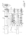
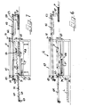
- a sliding surface U Arranged immediately downstream of the dividing machine, as a co-planar substantial extension of the working plane thereof, is a sliding surface U of such dimensions as to accommodate the packs of panels.
- the surface U is formed by the planar upper surface, optionally coated with a suitable material to avoid scratching the panels and help sliding said panels, of a plurality of beams 1 of any suitable section, parallel to each other and equally spaced apart, at right angles to the cutting line Z.
- Said beams are secured at their ends to transoms 2, 3 which are fixed to a frame 4 which is located parallelly and at a suitable distance below the grid-like frame formed by said beams 1.
- the frame 4 is transversely pivoted at 5 at the rear end thereof to support members 6' (see also Figure 3) of a structure 6 which is secured to the ground and is provided with support members 6" capable of supporting fluid-operated jacks 7 the plungers or rods of which are pivoted at 8 to said frame 4.
- the assembly 4-3-2-1 can be moved from the normal working position shown with full lines in Figure 2 to the dot-and-dash position wherein the front end of said assembly is directed upwards so as to form, immediately downstream of the cutting line Z an opening of such a width as to permit the off-cuts, resulting from the cutting operation on each large pack of panels originating said packs P, to be discharged.
- a conveyor 9, parallel to the cutting line Z, may be provided between the frame S and the front end of the structure 6, to collect said off-cuts and convey them out of the machine to suitable collection and disposal means.
- the sides of the frame 4 are provided with longitudinal guides 10 whereon a carriage 12 is moved on wheels 11, the side walls of said carriage being interconnected by transoms 12'-12" located above and below the frame 4.
- the carriage 12 is moved reciprocatingly and variously by a motor-reducer 13 mounted on the frame 4 and the output shaft of which carries a crank 14 which is connected to the carriage 12 through a connecting rod 15.
- the members 14 and 15 move in the space between the frame 4 and the grid-like frame formed by the beams 1.
- Secured to the upper transom 12" of the carriage 12 is the lower wing of a hinge 16 having a pivot 17 which is parallel to the line of cut Z.
- the upper wing of the hinge 16 has secured thereto similarly-shaped teeth 18 moving loosely in the spaces between the beams 1 and having co-planar ends 18' coated with such a material as to avoid marring the panels.
- the carriage 12 has associated therewith any suitable means whereby said teeth 18 will be moved to bring the ends 18' thereof either below the sliding surface U or suitably protruding upwardly therefrom.
- Said means may comprise, for example, small rollers 19 mounted at the front side of the upper wing of the hinge 16 and cooperating with inclined runways 20 supported by guides secured to the lower wing of said hinge, and actuated by jacks 21.
- each tooth 18, and each jack is in register with an end 18' of said teeth.
- a pad 25 is associated with the rod of each jack 24 and is preferably coated with such a material as to avoid marring the panels.
- the means moving the paddle 29 comprises two toggles 30 each connected to a side edge of the paddle and to a respective side member 26, and actuated by a respective jack 31.
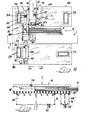
- Said station comprises a rectangular bed 32 resting on the floor through a base 33 and having affixed thereto, parallelly to the cutting line Z and suitably inter-spaced, a plurality of profiles 34 surmounted longitudinally by profiles 35 having an isosceles trapezoid configuration.
- profiles 35 having an isosceles trapezoid configuration.
- the latter profiles optionally coated with a suitable material, will constitute the grid-like surface whereon the packs of panels coming from the station B will slide.
- U-shaped profiles 36 Arranged parallelly intermediate the profiles 34-35, and co-planar therewith, are U-shaped profiles 36 having rotatably mounted therein a plurality of small wheels 37 of equal diameter and suitably protruding from the top side of said profiles and supporting the upper stretch of a belt 38.
- Each belt 38 closes through a return stretch under the wheels 37, and after passing around an idle wheel 39 said belt cooperates with a pulley 40 keyed on a shaft 41 rotatably supported by a side member of the bed 42 whereon the profiles 36 are fixed, the bed 42 being located inside the bed 32 and with its corner regions, and being connected to the rods of the jacks 43 supported on the base structure 6-33.
- a pulley 44 Keyed to the shaft 41 is a pulley 44 which is driven through a belt by a motor-reducer 45 fixed to the bed 42.
- this driving assembly By means of this driving assembly, the upper stretches of the belts 38 are moved to the transport line C ( Figure 1).
- said belts 38 may be held below the plane defined by the profiles 35, or they may be raised to protrude suitably from said plane to transfer the packs of panels to the transport line mentioned above.
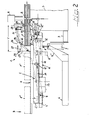
- the numeral 47 indicates a portion of the frame supporting a conventional lifting platform comprising a horizontal movable plane 48 designed to collect the packs of panels to be stacked at the station Q of Figure 1.
- Pivoted at 49 at the upper portion of the frame 47 are a pair of guides 50 which are interconnected at the front end thereof by a transom, which are so long as to be disposed longitudinally above the station B, and which are controlled by jacks 51 associated with the frame 47 in any suitable manner.
- the free end of said paddle is provided with a projection 58 so as to have an "L"-shape in plan view.
- the paddle 57 is operatively connected at 59 to the rod of a jack 60, the body of the jack 60 being connected at 61 to the carriage 53.
- the carriage 53 comprises suitable stiffening braces 53'.
- the jack 60 is activated to rotate the paddle 57 and, therefore, the row of packs P through an angle of 90° in an anti-clockwise direction when looking at Figure 1, and as shown with dotted lines in Figure 9.
- the projection 58 at the free end of the paddle 57 engages the outer end portion of the row of packs P and keeps said packs in an appropriate position.
- the latter is returned to its lifted rest position.
- Two parallel guides 64 interconnected by a rear transom and controlled by jacks 65 connected to the frame 47, are pivoted at 63 (below the pivots 49) to the frame 47 of the lifting platform at the station Q.
- a wedge member 67 which, similarly to the carriage 53, is connected to chains 68 controlled by a motor-reducer 69, can move longitudinally through its own wheels on the guides 64. Resting at the rear end of the wedge member 67 is a transverse doctor blade 70 which, through suitable end links, is pivotably connected at 72 to said guides 68.
- the guides 64 When the packs of panels are to be stacked on the platform 48, the guides 64 are raised as shown in Figure 7, whereby the upper surface of the wedge member 67 will be co-planar with sliding plane of the station B, to receive the packs P of panels therefrom. After the packs have reached the wedge 67, the guides 64 are lowered through the jacks 65, so that the lower surface of said wedge 67 reaches a position which is parallel and close to the top face of the pack P * of panels stacked on the platform 48, whereafter the wedge 67 is withdrawn by activating the motor-reducer 69. The blade 70 will sweep the wedge 67 and transfer the packs P of panels onto the stack P'.
- the upper panels of the stack P' may be put out of order, the latter engage against a side stop 70' integral with the frame of the lifting platform.
- the platform 48 is then lowered through a distance which is the same as the thickness of the packs P which have been discharged thereon, and the wedge 67 is moved back to its original position, whereafter the cycle is repeated. It is to be understood taht before activating the wedge 67, a plurality of panels from the station B may be stacked and arranged as desired thereon.
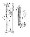
- the transport runway C ( Figure 1) is formed by four identical units of the type shown in Figure 10, arranged after each other and in a co-planar relationship, each of which comprises a bed 73 comprising a plurality of equi-spaced profiles which are parallel to each other and to the cutting line Z, said profiles being of the same type as those (35) forming the sliding plane of the station B, and being co-planar therewith.
- a bed 73 comprising a plurality of equi-spaced profiles which are parallel to each other and to the cutting line Z, said profiles being of the same type as those (35) forming the sliding plane of the station B, and being co-planar therewith.
- "U"-shaped profiles 74 Arranged parallelly intermediate the profiles of the bed 73, are "U"-shaped profiles 74 carrying longitudinal belts 75 driven by the common power unit 76, similarly to the arrangement shown in Figure 5 with regard to the station B.
- the profiles 74 are mounted on a common frame 77 supported by jacks 78 connected to the bed 73, the arrangement being such that the powered belts 75 may be maintained below the bed 73 or may be selectively lifted above said bed to advance the packs of panels toward the units D or D'.
- the transport runway C is formed by four units of the type mentioned above with reference to Figure 10, so that two of said transport units will be arranged in front of each unit D and D', so that while the one which is close to D or D' is stopped, the other unit may be left operative to receive new packs of panels from the station B and serve as a buffer unit, thus increasing the production rate of the machine of the invention.
- Opposite pairs of shoulders 80 are arranged at both sides of the runway C and are interconnected by transoms 79, and at least the one which is facing toward the stacking platforms T has a C-shape, as seen in Figure 11.
- the shoulders 80 are supported by guides, not shown, which are parallel to the longitudinal axis of the runway C and are operatively connected to means, such as pneumatic jacks, capable of selectively displacing the assembly 79-80 on said guides (the displacement being of the order of millimeters), first away from the station B and then back to the original position, as shown in Figure 11 by the arrows 145, 145'.
- means such as pneumatic jacks, capable of selectively displacing the assembly 79-80 on said guides (the displacement being of the order of millimeters), first away from the station B and then back to the original position, as shown in Figure 11 by the arrows 145, 145'.
- Slidably supported on said shoulders 80 through supports 81 are vertical racks 82 having affixed thereto the ends of a partition 83 disposed transversely on the runway C.
- the racks 82 are in mesh with pinions 84 keyed to the ends of a shaft 85 parallel to 83 and rotat
- the partition 83 can be either lowered across the runway C to stop the packs P of panels, or raised therefrom to permit the packs to pass towards further manipulation. It will be noted in Figure 1 that the unit D' is also provided with a movable partition 83 to enable the disposal, from the runway C, of the off-cuts possibly resulting from the severance of the packs of panels and which cannot be discharged downstream of the cutting line Z, as described with reference to Figure 2.
- a runway of rubber-sheathed rollers 87 arranged with their axes parallel to the longitudinal axis of the runway C is provided upstream of the partition 83.
- the rollers 87 are supported in different numbers, as shown at 87 and 87', by respective supporting structures 88-88' connected to the transom 79' through articulated links 89, each structure being controlled by jacks 90.
- the rollers of each group 87 and 87' are mechanically connected to each other and to the respective drive units 92 - 92' provided with hydrostatic couplings.
- the rollers 87 - 87' can rotate in the direction of the platforms T, and the rollers 87 which are in a smaller number are nearer to the row of said platforms T.
- rollers 87 - 87' and parallel thereto idle rollers or wheels 93 mounted on levers 94 which are resiliently urged downwards and are connected to a bar 95 parallel to the partition 83.
- the bar 95 is guided at the ends thereof by wheels 96 supported by the shoulders 80, and it supports a longitudinally rotatable shaft 97 having pinions 98 keyed to the ends thereof and meshing with vertical racks 99 secured to the shoulders 80.
- a pair of jacks 100 moves the presser 95 vertically.
- the unit D or D' described above operates as follows. The rollers 87 - 87' are normally lowered below the line of trasport C, while the presser 95 is in the maximum raised position.
- the partition 83 will first be lowered to stop the packs of panels P.
- the transport unit of the runway C located in front of the partition is disactivated by lowering the belts 75 which, preferably, will continue moving, while at due time the rollers 87 - 87' are raised and the presser 95 is lowered, whereby the front end of the pack or packs of panels will be raised from the sliding plane 73 and clamped between said rollers 87 - 87' and the upper wheels 93.
- the rollers 87 - 87' will be activated so that the packs of panels will be advanced after each other towards the sorting and stacking means E and will reach the latter while properly spaced apart because as soon as a pack has left the group of rollers 87, it is temporarily disactivated and lowered while the group of rollers 87' goes on operating. If the packs of panels have been transferred onto the runway C with no 90° rotation and, therefore, have reached the units D or D' after each other, the latter are characterized by an operation with cyclical displacement in the direction of the arrows 145 - 145', whereby the packs will not contact each other.
- the respective partition 83 may be left in its lowered position or it may be raised if desired and possible.
- the hydraulic couplings for the drive units 92 - 92' of the rollers 87 - 87' will ensure a displacement of the packs with a soft start, thus avoiding compromising the orderly assembly of the packs.
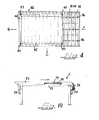
- the invention provides a similar transport runway formed by rollers 109, also suitably sheathed, driven by suitable means 110 and supported by a structure 111 pivotably mounted on a shaft 112 which is rotatably mounted on shoulders 101 and parallel to the bar 104.
- Suitable jacks 113 the bodies of which are connected to a depending projection 101' of the shoulders 101 and the rods of which are connected to the ends of the structure 111, control the position of said structure and rollers 109 mounted thereon.
- idle sheathed rollers 114 are provided and are supported by a structure 115 also pivotably secured to a shaft 116 which is parallel to the shaft 112 but, unlike the latter, is supported by a carriage 117 capable of sliding horizontally on the shoulders 101 towards and away from the bar 104 as shown diagrammatically by the arrows 118.
- Means of any type, even if of no high precision (not shown), are provided for displacing the carriage 117 and are connected thereto at the ends of depending projections 119 capable of supporting the bodies of jacks 120, the rods of the latter being pivotably connected to the structure 115 to control the position of the latter and of respective rollers 114.
- the invention provides selectively-retractible partitions.
- the partition 129 of that platform is lowered at due time so that said partition will stop the pack being transferred by the units E of Figure 13.
- suitable sequential means will stop the lower rollers 109 of the respective unit E and the jacks 113, 120 are timely retracted whereby the rollers 109 and 114 will be also retracted laterally of the pack P which, therefore, will rest on the teeth 121 and 122.
- the synchronous extension of jacks 125, 126 is controlled whereby the teeth 121, 122 will be lowered and will protrude progressively from the guide barriers 127 - 128, while the pack P will be smoothly laid on the top of the stack P' of panels previously stacked on the platform T and also retained partly by said lateral barriers 127 - 128. If the lifting platform T is empty, the plane thereof will be partly inserted between the grids 127 - 128 so that it can receive the pack of panels as well, with no appreciable dropping effect.
- each lifting platform T whereon a pack P has been discharged is lowered by an extent equal to the thickness of said pack P, and thereafter the rollers 109 and 114 as well as the teeth 121, 122 will be returned to their active positions as shown in Figure 13, said rollers 109 will be rotated again and, if necessary, the previously-lowered partition 129 is raised.
- each lifting platform is provided with a unit E of the type of Figure 13, with independent controls, while one of these units is in the stacking step, the other units pertaining to the same row of platforms T can be in operative conditions for buffering purposes of the packs P coming from the units D or D'.
- the movable table 130 of the lifting platforms T is of comb-like formation and is supported in cantilever fashion by a carriage 131 sliding within a vertical guide structure 132 and driven by suitable means 133 comprising, for example, a motor-reducer and chains.
- the bedplate 134 for the platforms T is engaged by extensions 135' of the parallel runways with idle rollers 135 constituting the stations G in front of said platforms T, a transverse bar 136 being longitudinally slidable under said runways and having secured thereto teeth 137 protruding upwards from said runways and normally in a retracted position within the outline of the guide structure 132 .
- the table 130 of said platform is completely lowered so that due to its comb-like formation it will be interleaved between the runways 135 and will be lowered below said runways which, therefore, will take over in supporting said stack P l .
- the bar 136 will be actuated and will engage, through its teeth 137, the stack P' making the latter slide along the runways 135' - 135.
- the stacks P' may either be built up in the stations G or they may be transferred directly onto the powered roller runways H-H'.
Landscapes
- Engineering & Computer Science (AREA)
- Mechanical Engineering (AREA)
- Life Sciences & Earth Sciences (AREA)
- Wood Science & Technology (AREA)
- Forests & Forestry (AREA)
- Stacking Of Articles And Auxiliary Devices (AREA)
- Specific Conveyance Elements (AREA)
- Respiratory Apparatuses And Protective Means (AREA)
- Transition And Organic Metals Composition Catalysts For Addition Polymerization (AREA)
- Eye Examination Apparatus (AREA)
- Pallets (AREA)
- Forklifts And Lifting Vehicles (AREA)
- Load-Engaging Elements For Cranes (AREA)
Priority Applications (1)
| Application Number | Priority Date | Filing Date | Title |
|---|---|---|---|
| AT83106003T ATE34722T1 (de) | 1982-06-24 | 1983-06-20 | Maschine zum automatischen stapeln von plattenpaketen mit unterschiedlichen groessen auf betreffende hebeplattformen. |
Applications Claiming Priority (2)
| Application Number | Priority Date | Filing Date | Title |
|---|---|---|---|
| IT346182 | 1982-06-24 | ||
| IT03461/82A IT1156610B (it) | 1982-06-24 | 1982-06-24 | Impianto per impilare automaticamente su rispettive tavole elevatrici, pannelli o pacchi di pannelli di dimensione diversa, prodotti da un impianto di sezionatura |
Publications (3)
| Publication Number | Publication Date |
|---|---|
| EP0106019A2 true EP0106019A2 (de) | 1984-04-25 |
| EP0106019A3 EP0106019A3 (en) | 1984-07-04 |
| EP0106019B1 EP0106019B1 (de) | 1988-06-01 |
Family
ID=11107802
Family Applications (1)
| Application Number | Title | Priority Date | Filing Date |
|---|---|---|---|
| EP83106003A Expired EP0106019B1 (de) | 1982-06-24 | 1983-06-20 | Maschine zum automatischen Stapeln von Plattenpaketen mit unterschiedlichen Grössen auf betreffende Hebeplattformen |
Country Status (9)
| Country | Link |
|---|---|
| US (1) | US4576536A (de) |
| EP (1) | EP0106019B1 (de) |
| AT (1) | ATE34722T1 (de) |
| BR (1) | BR8303371A (de) |
| CA (1) | CA1206492A (de) |
| DE (1) | DE3376826D1 (de) |
| ES (1) | ES8404782A1 (de) |
| FI (1) | FI81549C (de) |
| IT (1) | IT1156610B (de) |
Cited By (8)
| Publication number | Priority date | Publication date | Assignee | Title |
|---|---|---|---|---|
| EP0205064A2 (de) | 1985-06-07 | 1986-12-17 | GIBEN IMPIANTI S.p.A. | Anlage zum automatischen Stapeln und Ausrichten von Plattenstapeln unterschiedlicher Grösse |
| GB2262729A (en) * | 1991-12-26 | 1993-06-30 | Tadao Uno | Device for piling bundles of sheets |
| FR2692567A1 (fr) * | 1992-06-23 | 1993-12-24 | Uno Tadao | Système d'empilement de paquets de feuilles en trois dimensions. |
| ES2078841A2 (es) * | 1992-06-23 | 1995-12-16 | Tadao Uno | Sistema de apilamiento tridimensional de paquetes de hojas. |
| WO1999020441A1 (en) * | 1997-10-16 | 1999-04-29 | Giben Impianti S.P.A. | Method and device for feeding panels to a panel saw machine |
| ITBO20120143A1 (it) * | 2012-03-19 | 2013-09-20 | Giben Int Spa | Stazione di sezionamento pannelli. |
| WO2018149540A1 (de) * | 2017-02-15 | 2018-08-23 | Windmöller & Hölscher Kg | Transportvorrichtung, system zum stapeln von gefüllten säcken, sowie verfahren zum stapeln von gefüllten säcken |
| CN109318299A (zh) * | 2018-11-22 | 2019-02-12 | 东阳市旭东工艺品有限公司 | 一种红木家具加工生产线 |
Families Citing this family (11)
| Publication number | Priority date | Publication date | Assignee | Title |
|---|---|---|---|---|
| ES2016320B3 (es) * | 1986-10-23 | 1990-11-01 | Erwin Jenkner | Instalacion para la distribucion de placas para el transporte de apilamiento de recortes |
| DE4022350A1 (de) * | 1990-07-13 | 1992-01-16 | Bielomatik Leuze & Co | Foerdereinrichtung fuer lageneinheiten |
| ITBO20030645A1 (it) * | 2003-10-31 | 2005-05-01 | Giben Int Spa | Dispositivo per la rotazione di pannelli. |
| ITBO20050198A1 (it) * | 2005-03-29 | 2006-09-30 | Gruppo Barbieri & Tarozzi S P A | Metodo e impianto |
| US8074957B2 (en) | 2008-09-25 | 2011-12-13 | Prime Forming & Construction Supplies, Inc. | Formliner and method of use |
| USD791364S1 (en) | 2014-09-25 | 2017-07-04 | Prime Forming & Construction Supplies, Inc. | Formliner |
| US20160237704A1 (en) | 2015-02-14 | 2016-08-18 | Prime Forming & Construction Supplies, Inc., dba Fitzgerald Formliners | Formliners and methods of use |
| AU2016380689B2 (en) | 2015-12-28 | 2022-06-30 | Prime Forming & Construction Supplies, Inc., dba Fitzgerald Formliners | Formliner for forming a pattern in curable material and method of use |
| CN108082880B (zh) * | 2018-01-22 | 2023-12-26 | 山东昶兴智能科技有限公司 | 一种多层胶合板全自动生产线 |
| CN112373939B (zh) * | 2020-11-02 | 2022-07-22 | 梅州市金西湖实业有限公司 | 一种混纺面料的加工工艺 |
| CN114524317B (zh) * | 2022-03-16 | 2023-03-31 | 徐州华睿炭材料科技有限公司 | 一种用于活性炭滤布的生产装置 |
Citations (4)
| Publication number | Priority date | Publication date | Assignee | Title |
|---|---|---|---|---|
| AT333662B (de) * | 1973-12-21 | 1976-12-10 | Schelling & Co | Einrichtung bei holzbearbeitungsmaschinen, insbesondere bei plattenaufteilanlagen |
| AT333663B (de) * | 1974-03-20 | 1976-12-10 | Schelling & Co | Einrichtung zur aufnahme und weitergabe bzw. zum abstapeln plattenformiger werkstucke |
| DE2534437A1 (de) * | 1975-07-30 | 1977-02-10 | Hans V Schmidt | Rollen-foerdereinrichtung mit auf- und abgabe-vorrichtung |
| AT343538B (de) * | 1976-10-04 | 1978-06-12 | Schelling & Co | Plattenaufteil- und sortieranlage mit mindestens einer stapeleinrichtung |
Family Cites Families (6)
| Publication number | Priority date | Publication date | Assignee | Title |
|---|---|---|---|---|
| FR683167A (fr) * | 1929-01-14 | 1930-06-06 | Transporteur-déplaceur pour plaques à biscuits ou autres produits similaires avant leur entrée dans le four | |
| US2933207A (en) * | 1957-06-19 | 1960-04-19 | Structural Clay Products Res F | Unit stacking apparatus |
| US3084812A (en) * | 1958-10-29 | 1963-04-09 | Nordstroems Linbanor Ab | Means for stacking of sheets |
| US4018351A (en) * | 1976-03-04 | 1977-04-19 | Stobb, Inc. | Apparatus for handling bundles of sheets |
| IT1124199B (it) * | 1979-10-12 | 1986-05-07 | Giben Impianti Spa | Dispositivo per raccogliere e per impilare automaticamente su una o su piu tavole elevatrici i pacchi di pannelli tagliati in uscita da un impianto di sezionatura |
| DE3021124A1 (de) * | 1980-06-04 | 1981-12-17 | E.C.H. Will (Gmbh & Co), 2000 Hamburg | Anordnung zum ansammeln von gebundenen blaettern, z.b. schreibartikel |
-
1982
- 1982-06-24 IT IT03461/82A patent/IT1156610B/it active
-
1983
- 1983-06-20 DE DE8383106003T patent/DE3376826D1/de not_active Expired
- 1983-06-20 AT AT83106003T patent/ATE34722T1/de not_active IP Right Cessation
- 1983-06-20 EP EP83106003A patent/EP0106019B1/de not_active Expired
- 1983-06-22 CA CA000430911A patent/CA1206492A/en not_active Expired
- 1983-06-22 US US06/506,939 patent/US4576536A/en not_active Expired - Lifetime
- 1983-06-22 FI FI832288A patent/FI81549C/fi not_active IP Right Cessation
- 1983-06-23 ES ES523529A patent/ES8404782A1/es not_active Expired
- 1983-06-23 BR BR8303371A patent/BR8303371A/pt unknown
Patent Citations (4)
| Publication number | Priority date | Publication date | Assignee | Title |
|---|---|---|---|---|
| AT333662B (de) * | 1973-12-21 | 1976-12-10 | Schelling & Co | Einrichtung bei holzbearbeitungsmaschinen, insbesondere bei plattenaufteilanlagen |
| AT333663B (de) * | 1974-03-20 | 1976-12-10 | Schelling & Co | Einrichtung zur aufnahme und weitergabe bzw. zum abstapeln plattenformiger werkstucke |
| DE2534437A1 (de) * | 1975-07-30 | 1977-02-10 | Hans V Schmidt | Rollen-foerdereinrichtung mit auf- und abgabe-vorrichtung |
| AT343538B (de) * | 1976-10-04 | 1978-06-12 | Schelling & Co | Plattenaufteil- und sortieranlage mit mindestens einer stapeleinrichtung |
Cited By (13)
| Publication number | Priority date | Publication date | Assignee | Title |
|---|---|---|---|---|
| EP0205064A3 (en) * | 1985-06-07 | 1987-04-08 | Giben Impianti S.P.A. | A plant for automatically stacking and orderly arranging packs of panels of different sizes |
| EP0205064A2 (de) | 1985-06-07 | 1986-12-17 | GIBEN IMPIANTI S.p.A. | Anlage zum automatischen Stapeln und Ausrichten von Plattenstapeln unterschiedlicher Grösse |
| GB2262729B (en) * | 1991-12-26 | 1996-04-03 | Tadao Uno | Device for piling bundles of sheets |
| GB2262729A (en) * | 1991-12-26 | 1993-06-30 | Tadao Uno | Device for piling bundles of sheets |
| FR2692567A1 (fr) * | 1992-06-23 | 1993-12-24 | Uno Tadao | Système d'empilement de paquets de feuilles en trois dimensions. |
| ES2078841A2 (es) * | 1992-06-23 | 1995-12-16 | Tadao Uno | Sistema de apilamiento tridimensional de paquetes de hojas. |
| NL9300007A (nl) * | 1992-06-23 | 1994-01-17 | Uno Tadao | Drie-dimensioneel opstapelsysteem voor blokken vellen. |
| WO1999020441A1 (en) * | 1997-10-16 | 1999-04-29 | Giben Impianti S.P.A. | Method and device for feeding panels to a panel saw machine |
| US6481954B1 (en) * | 1997-10-16 | 2002-11-19 | Giben Impianti S.P.A. | Method and device for feeding panels to a panel saw machine |
| ITBO20120143A1 (it) * | 2012-03-19 | 2013-09-20 | Giben Int Spa | Stazione di sezionamento pannelli. |
| WO2018149540A1 (de) * | 2017-02-15 | 2018-08-23 | Windmöller & Hölscher Kg | Transportvorrichtung, system zum stapeln von gefüllten säcken, sowie verfahren zum stapeln von gefüllten säcken |
| US11091329B2 (en) | 2017-02-15 | 2021-08-17 | Windmöller & Hölscher Kg | Conveying device, system for stacking filled bags, and method for stacking filled bags |
| CN109318299A (zh) * | 2018-11-22 | 2019-02-12 | 东阳市旭东工艺品有限公司 | 一种红木家具加工生产线 |
Also Published As
| Publication number | Publication date |
|---|---|
| CA1206492A (en) | 1986-06-24 |
| US4576536A (en) | 1986-03-18 |
| DE3376826D1 (en) | 1988-07-07 |
| BR8303371A (pt) | 1984-02-07 |
| ES523529A0 (es) | 1984-05-16 |
| ES8404782A1 (es) | 1984-05-16 |
| FI832288A0 (fi) | 1983-06-22 |
| FI832288L (fi) | 1983-12-25 |
| EP0106019A3 (en) | 1984-07-04 |
| IT8203461A0 (it) | 1982-06-24 |
| ATE34722T1 (de) | 1988-06-15 |
| EP0106019B1 (de) | 1988-06-01 |
| FI81549C (fi) | 1990-11-12 |
| FI81549B (fi) | 1990-07-31 |
| IT1156610B (it) | 1987-02-04 |
Similar Documents
| Publication | Publication Date | Title |
|---|---|---|
| US4576536A (en) | Machine for stacking automatically packs of panels of different sizes on respective lifting platforms | |
| US4986726A (en) | Plant for automatically stacking and orderly arranging packs of panels of different sizes | |
| US4352616A (en) | Device for arranging objects in stacking layers, for loading pallets | |
| JPH046514B2 (de) | ||
| US3381828A (en) | Filled-bag stacking palletizer | |
| US5829951A (en) | Collecting and stacking device for laminar sheets and stacking method | |
| CA2482282C (en) | Apparatus for stacking elongated members | |
| US6155775A (en) | Destacking feeder | |
| US7243479B2 (en) | Apparatus and method for loading a packaging station of an insulation batt packager | |
| US4614473A (en) | Method and apparatus for the stacking of rectangular products | |
| US3437215A (en) | Lumber stacker | |
| US3640407A (en) | Apparatus for handling books | |
| US2895624A (en) | Elevator for use in a lumber stacker | |
| US3776404A (en) | Method of handling books | |
| US2645329A (en) | Mechanism for handling boards | |
| JPH08268550A (ja) | 条鋼精整装置 | |
| JPH08175662A (ja) | 搬送−仕分け−および貯蔵装置 | |
| US5511935A (en) | Paper stack conveyor | |
| EP0455134A1 (de) | Vorrichtung zum Verlegen von Paneelenstapeln in einer Schneidenanlage von Winkelart | |
| US3224307A (en) | Method and apparatus for handling sheet materials | |
| CN210939515U (zh) | 一种智能物流裁切生产线 | |
| US3519144A (en) | Stacking system for paperboard blanks | |
| CN109552928B (zh) | 一种瓦楞纸板堆码机 | |
| US6189679B1 (en) | Lumber spacing stick conveyor meter | |
| US5171125A (en) | Sheet material handling apparatus and method having a pivotable hopper and bottom feeder |
Legal Events
| Date | Code | Title | Description |
|---|---|---|---|
| PUAI | Public reference made under article 153(3) epc to a published international application that has entered the european phase |
Free format text: ORIGINAL CODE: 0009012 |
|
| AK | Designated contracting states |
Designated state(s): AT BE CH DE FR GB LI LU NL SE |
|
| PUAL | Search report despatched |
Free format text: ORIGINAL CODE: 0009013 |
|
| RHK1 | Main classification (correction) |
Ipc: B65G 37/00 |
|
| AK | Designated contracting states |
Designated state(s): AT BE CH DE FR GB LI LU NL SE |
|
| 17P | Request for examination filed |
Effective date: 19840925 |
|
| GRAA | (expected) grant |
Free format text: ORIGINAL CODE: 0009210 |
|
| AK | Designated contracting states |
Kind code of ref document: B1 Designated state(s): AT BE CH DE FR GB LI LU NL SE |
|
| PG25 | Lapsed in a contracting state [announced via postgrant information from national office to epo] |
Ref country code: NL Effective date: 19880601 Ref country code: BE Effective date: 19880601 |
|
| REF | Corresponds to: |
Ref document number: 34722 Country of ref document: AT Date of ref document: 19880615 Kind code of ref document: T |
|
| PG25 | Lapsed in a contracting state [announced via postgrant information from national office to epo] |
Ref country code: LU Free format text: LAPSE BECAUSE OF NON-PAYMENT OF DUE FEES Effective date: 19880630 |
|
| REF | Corresponds to: |
Ref document number: 3376826 Country of ref document: DE Date of ref document: 19880707 |
|
| ET | Fr: translation filed | ||
| NLV1 | Nl: lapsed or annulled due to failure to fulfill the requirements of art. 29p and 29m of the patents act | ||
| PLBE | No opposition filed within time limit |
Free format text: ORIGINAL CODE: 0009261 |
|
| STAA | Information on the status of an ep patent application or granted ep patent |
Free format text: STATUS: NO OPPOSITION FILED WITHIN TIME LIMIT |
|
| 26N | No opposition filed | ||
| PGFP | Annual fee paid to national office [announced via postgrant information from national office to epo] |
Ref country code: SE Payment date: 19890525 Year of fee payment: 7 |
|
| PGFP | Annual fee paid to national office [announced via postgrant information from national office to epo] |
Ref country code: GB Payment date: 19890630 Year of fee payment: 7 Ref country code: FR Payment date: 19890630 Year of fee payment: 7 |
|
| PGFP | Annual fee paid to national office [announced via postgrant information from national office to epo] |
Ref country code: CH Payment date: 19890830 Year of fee payment: 7 |
|
| PG25 | Lapsed in a contracting state [announced via postgrant information from national office to epo] |
Ref country code: GB Effective date: 19900620 |
|
| PG25 | Lapsed in a contracting state [announced via postgrant information from national office to epo] |
Ref country code: SE Effective date: 19900621 |
|
| PG25 | Lapsed in a contracting state [announced via postgrant information from national office to epo] |
Ref country code: LI Effective date: 19900630 Ref country code: CH Effective date: 19900630 |
|
| GBPC | Gb: european patent ceased through non-payment of renewal fee | ||
| PG25 | Lapsed in a contracting state [announced via postgrant information from national office to epo] |
Ref country code: FR Effective date: 19910228 |
|
| REG | Reference to a national code |
Ref country code: CH Ref legal event code: PL |
|
| REG | Reference to a national code |
Ref country code: FR Ref legal event code: ST |
|
| EUG | Se: european patent has lapsed |
Ref document number: 83106003.3 Effective date: 19910206 |
|
| PGFP | Annual fee paid to national office [announced via postgrant information from national office to epo] |
Ref country code: DE Payment date: 19990623 Year of fee payment: 17 |
|
| PGFP | Annual fee paid to national office [announced via postgrant information from national office to epo] |
Ref country code: AT Payment date: 19990630 Year of fee payment: 17 |
|
| PG25 | Lapsed in a contracting state [announced via postgrant information from national office to epo] |
Ref country code: AT Free format text: LAPSE BECAUSE OF NON-PAYMENT OF DUE FEES Effective date: 20000620 |
|
| PG25 | Lapsed in a contracting state [announced via postgrant information from national office to epo] |
Ref country code: DE Free format text: LAPSE BECAUSE OF NON-PAYMENT OF DUE FEES Effective date: 20010403 |