EP0105751B1 - Verfahren und Vorrichtung zum Formen eines Rohrkörpers mit verminderter Ziehkraft - Google Patents
Verfahren und Vorrichtung zum Formen eines Rohrkörpers mit verminderter Ziehkraft Download PDFInfo
- Publication number
- EP0105751B1 EP0105751B1 EP83305953A EP83305953A EP0105751B1 EP 0105751 B1 EP0105751 B1 EP 0105751B1 EP 83305953 A EP83305953 A EP 83305953A EP 83305953 A EP83305953 A EP 83305953A EP 0105751 B1 EP0105751 B1 EP 0105751B1
- Authority
- EP
- European Patent Office
- Prior art keywords
- strip
- tube
- join
- die
- region
- Prior art date
- Legal status (The legal status is an assumption and is not a legal conclusion. Google has not performed a legal analysis and makes no representation as to the accuracy of the status listed.)
- Expired
Links
Images
Classifications
-
- B—PERFORMING OPERATIONS; TRANSPORTING
- B21—MECHANICAL METAL-WORKING WITHOUT ESSENTIALLY REMOVING MATERIAL; PUNCHING METAL
- B21C—MANUFACTURE OF METAL SHEETS, WIRE, RODS, TUBES, PROFILES OR LIKE SEMI-MANUFACTURED PRODUCTS OTHERWISE THAN BY ROLLING; AUXILIARY OPERATIONS USED IN CONNECTION WITH METAL-WORKING WITHOUT ESSENTIALLY REMOVING MATERIAL
- B21C37/00—Manufacture of metal sheets, rods, wire, tubes, profiles or like semi-manufactured products, not otherwise provided for; Manufacture of tubes of special shape
- B21C37/06—Manufacture of metal sheets, rods, wire, tubes, profiles or like semi-manufactured products, not otherwise provided for; Manufacture of tubes of special shape of tubes or metal hoses; Combined procedures for making tubes, e.g. for making multi-wall tubes
- B21C37/08—Making tubes with welded or soldered seams
- B21C37/083—Supply, or operations combined with supply, of strip material
-
- G—PHYSICS
- G02—OPTICS
- G02B—OPTICAL ELEMENTS, SYSTEMS OR APPARATUS
- G02B6/00—Light guides; Structural details of arrangements comprising light guides and other optical elements, e.g. couplings
- G02B6/44—Mechanical structures for providing tensile strength and external protection for fibres, e.g. optical transmission cables
- G02B6/4479—Manufacturing methods of optical cables
- G02B6/4486—Protective covering
- G02B6/4488—Protective covering using metallic tubes
Definitions
- the invention disclosed herein relates to a process for the manufacture of armoured optical fibre communication cable.
- tubular member or tube In forming communication cables, it is often necessary to provide a metal or metal alloy tubular member or tube to protect critical elements such as optical fibres, electrical conductors, and the like.
- the tubular member may serve as an electrical conductor itself or act as a fluid barrier.
- the tubular members required for_ such cables have relatively long lengths, i.e. multi-kilometer lengths. Finding a suitable technique for forming such long tubes can be a problem. As well as dealing with the length problem, the tube forming technique must be capable of forming tubular members that can be readily and effectively sealed. In optical fibre cable fabricaton techniques, these problems are compounded by the problems associated with insertion of the optical fibre or fibres and/or any void filler into the tube.
- Another approach for forming a tube from strip material is die forming.
- the tube is formed by drawing a strip of metal or metal alloy through a die.
- Manufacturing Processes Sixth Edition by Myron L. Begeman et al., John Wiley and Sons, Inc., 1957, pp. 283-285 suggests various dies for forming a tube from strip material.
- the force exerted on the strip during this process is known as the drawing force.
- the drawing force has two components, the forming force and the deformation force.
- the forming force is the useful work component in making the tube. It arises from applying tension to the strip to draw the strip through the die and to cause the strip to fold over and form a tube.
- the deformation force is the work component that increases the length by redistributing the excess volume of strip material.
- the drawing force acts not only on the parent strip material but on any joints interconnecting the strips.
- the drawing force exceeds the tensile breaking strength of the parent strip material or the tensile breaking strength of a joint, the material will break. Breakage generally occurs in the die while the strip is changing directions. While it is possible to repair the broken strip by patching the pieces together, the patch often adversely affects desirable mechanical properties such as temper, electrical conductivity, thermal conductivity and tensile strength.
- the problem of material breakage, particularly at a joint, as a result of excessive drawing force is particularly troublesome in die forming techniques where the tube is formed from a strip having an initial cross-sectional area greater than the cross-sectional area of the tube to be formed.
- This approach is used where it is desired to assure sufficient interference compressive force acting on the edges that the formed tube has a longitudinal seam created by substantially abutting edges which are held closed by residual compressive stresses.
- This technique compounds the drawing force problem because the extra area increases the deformation force which in turn increases the drawing force.
- the problem of tensile breaking of the joint as a jointed strip is drawn through the die in the manufacture of armoured optical fibre communication cable can be solved by giving the strip, in the region of that join, a profile, e.g. a trapezoidal section, formed by shaping one or both longitudinal edges of the strip in the region of the join, that profile being such that the drawing force required to pull the join through the die is less than that which is required to draw the rest of the strip through the die.
- a profile e.g. a trapezoidal section
- the formed tube While one could eliminate the deformation force altogether, it is important that the formed tube be as hard as possible. Since the deformation force extension increases the mechanical properties of the material forming the tube, some deformation is desirable.
- the process of the instant invention has been found to have sufficient deformation to increase the temper and the ultimate yield strength of the material without decreasing formability.
- the process of the instant invention draws the strip through a die to work harden the material and increase its temper and ultimate yield strength.
- the tube formed by the instant process tends to have a substantially square and tight seam that may be easily sealed with a relatively high degree of hermeticity.
- the edge portions of the strip adjacent the join are shaped prior to any bonding operation to interconnect lengths of strip.
- the shaping of the edge portions may be done in any conventional manner. While the edge portions may be provided with a wide variety of suitable shapes, it has been found that providing the edge portions with a trapezoidal cross-section is particularly beneficial.
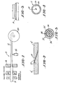
- Strip 14 is normally received in the form of a coil and comes from suitable payoff equipment not shown.
- the payoff equipment should be such that a back tension may be applied to the strip if desired.
- Strip 14 is not a single length of material but comprises a plurality of lengths 14' and 14", see Figure 2, joined together.
- the individual lengths may be joined in any suitable manner.
- conventional joining techniques such as brazing, soldering, welding, and diffusion bonding may be used.
- Strip 14 may be formed from any metal or metal alloy that exhibits a desired set of strength, formability and/or conductivity characteristics.
- the strip may be in any desired condition.
- strip 14 is in a wrought and partially work hardened form. It should have a hardness or strength sufficient to enable it to be formed into a tube by drawing through die 18.
- the strip 14 Prior to being fed into apparatus 10, the strip 14 may be fed to a suitable cleaning system- not shown for removal of contaminants.
- the cleaning system utilized will depend upon the metal or metal alloy forming the strip and the nature of the contaminants to be removed. Any suitable conventional cleaning system known in the art may be utilized.
- Strip 14 is fed into apparatus 10 by connecting it via any suitable means known in the art to take-up reel 20.
- Take-up reel 20 applies a tension force to the strip and draws or pulls the strip through formed die 18.
- Forming die 18 may comprise any suitable die arrangement known in the art. Manufacturing Processes, Sixth Edition, by Myron L. Begeman et al., John Wiley and Sons, Inc., 1957, pp. 283-285 suggests various die arrangements suitable for forming a tube from strip material.
- die 18 is a metal die arrangement.
- strip 14 Prior to being fed into die 18, strip 14 preferably passes through a fluxing station 22.
- the fluxing station comprises any conventional means known in the art for applying any conventional flux.
- Fluxing station 22 applies the flux to the edges of the strip. Since the fluxing station is not absolutely necessary to form the tube 12, it may be omitted if desired.
- strip 14 preferably has an initial cross-sectional area greater than the cross-sectional area 26 of the formed tube. It has been found that by providing the strip with such an initial area, sufficient interference compressive force acts on the strip edges that a substantially square and tight seam is formed by the substantially abutting edges 40. This type of seam may be more readily and more effectively sealed providing improved hermeticity and generally requires less sealing material.
- the initial area should be about 5% to about 20%, preferably from about 10% to about 15%, greater than the tube cross-sectional area.
- the drawing force is equal to the sum of two other forces, the forming force and the deformation force.
- the forming force is essentially the force required to fold the strip over and form the tube 12.
- the forming force arises from the tension applied to the strip to pull it through the die.
- the deformation force causes tube extension and arises out of a redistribution of the strip material.
- the deformation force can be particularly troublesome in situations where there is a substantial excess volume of strip material.
- the deformation force and consequently the drawing force exerted on the joint 16 may be reduced by shaping the edge portions of the strip in the region of that joint. By reducing the drawing force, the likelihood of the drawing force exceeding the tensile breaking strength of the joint and causing breakage is reduced. It has been discovered that providing the strip edge portions adjacent the joint with a trapezoidal cross-sectional shape such as that illustrated in Figure 3 is particularly advantageous. When drawn through the die, the trapezoid base b forms the outer tube circumference 26 and the shorter side a forms the inner tube circumference 28.
- strip edge portions could be provided with other suitable cross-sectional shapes.
- any other suitable shape may be utilized as long as it leads to a reduction in the drawing force as the joint passes through the die.
- Providing the edge portions of the strip with a shaped cross-section has several advantages. First, it reduces. the amount or volume of material that has to be redistributed, thus lowering the deformation force. Second, the material is redistributed so that the seam 24 is characterised by substantially abutting and substantially parallel edges 40.
- Shaping of the strip edge portions adjacent the joint may be performed in any suitable manner by any well known shaping means 11.
- the shaping means 11 may comprise any conventional scarfing apparatus, skiving apparatus, cutting blade, or the like, and preferably the shaping occurs prior to any bonding operation to join the strips together.
- mating surfaces 30 of strips 14' and 14" would be shaped prior to the formation of joint 16.
- the instant process causes an extension in the tube length as compared to the original length of the strip. This extension is effected without any substantial wall thinning.
- the tube extension has been found to be substantially equal to any difference between the initial strip cross-sectional area and the tube cross-sectional area.
- sealing station 32 may comprise any conventional sealing apparatus for soldering, welding, brazing or applying any other suitable sealing techniques.
- seam 24 is filled with a suitable closing material 34 such as solder.
- the process described is specifically concerned with the manufacture of armoured optical fibre communication cables 37 in which the tube is used as a metal armouring 35 to protect the optical fibre or fibres.
- the tube 35 may act as an electrical conductor and/or a fluid barrier.
- the metal armouring 35 surrounds one or more optical fibres 36.
- Each optical fibre is generally embedded within a suitable plastic protective layer 38 such as a polyethylene sheath.
- the outer diameter of the sheath may be substantially equal to the inner diameter of the armour tube 35 or there may be a void between each sheath 38 and the tube 35. If a void is present, it may be filled with a suitable filler material to further protect the optical fibre. Alternatively, the filler material may be omitted.
- the tube formed in accordance with the instant invention may have any desired thickness to diameter ratio.
- the thickness to diameter ratio of the tube preferably is from about 0.02:1 to about 0.5:1 and most preferably from about 0.01 : 1 to about 0.3: 1.
- the tube 12 may be formed from any desired metal or metal alloy. Where combinations of strength and conductivity are required, copper and its alloys and steel, e.g. stainless steel, may be utilized.
- shaping edge portions also includes shaping part of the face of an edge. portion.
Landscapes
- Engineering & Computer Science (AREA)
- Physics & Mathematics (AREA)
- Manufacturing & Machinery (AREA)
- General Physics & Mathematics (AREA)
- Optics & Photonics (AREA)
- Mechanical Engineering (AREA)
- Metal Extraction Processes (AREA)
Claims (7)
Applications Claiming Priority (2)
| Application Number | Priority Date | Filing Date | Title |
|---|---|---|---|
| US06/430,069 US4557559A (en) | 1982-09-30 | 1982-09-30 | Process for die forming a tubular member at a reduced drawing force |
| US430069 | 1982-09-30 |
Publications (2)
| Publication Number | Publication Date |
|---|---|
| EP0105751A1 EP0105751A1 (de) | 1984-04-18 |
| EP0105751B1 true EP0105751B1 (de) | 1986-12-03 |
Family
ID=23705937
Family Applications (1)
| Application Number | Title | Priority Date | Filing Date |
|---|---|---|---|
| EP83305953A Expired EP0105751B1 (de) | 1982-09-30 | 1983-09-30 | Verfahren und Vorrichtung zum Formen eines Rohrkörpers mit verminderter Ziehkraft |
Country Status (5)
| Country | Link |
|---|---|
| US (1) | US4557559A (de) |
| EP (1) | EP0105751B1 (de) |
| JP (1) | JPS5982112A (de) |
| CA (1) | CA1205757A (de) |
| DE (1) | DE3368024D1 (de) |
Families Citing this family (9)
| Publication number | Priority date | Publication date | Assignee | Title |
|---|---|---|---|---|
| US4949894A (en) * | 1984-06-07 | 1990-08-21 | Olin Corporation | Method and apparatus for forming ultra-small optical fiber cable assemblies |
| US4802730A (en) * | 1986-11-10 | 1989-02-07 | Olin Corporation | Optical fiber cables for motor vehicle engine compartment applications |
| US4759487A (en) * | 1987-03-09 | 1988-07-26 | K-Tube Corporation | Apparatus for continuous manufacture of armored optical fiber cable |
| US4925300A (en) * | 1988-08-02 | 1990-05-15 | Rachlin Daniel J | Optical fingerprint imaging device |
| US9199315B2 (en) | 2000-06-02 | 2015-12-01 | Kennametal Inc. | Twist drill and method for producing a twist drill which method includes forming a flute of a twist drill |
| US6748147B2 (en) | 2001-03-30 | 2004-06-08 | Corning Cable Systems Llc | High strength fiber optic cable |
| US6714708B2 (en) | 2001-03-30 | 2004-03-30 | Corning Cable Systems Llc | Fiber optic with high strength component |
| US6621964B2 (en) | 2001-05-21 | 2003-09-16 | Corning Cable Systems Llc | Non-stranded high strength fiber optic cable |
| DE102011016170A1 (de) * | 2011-04-05 | 2012-10-11 | Faurecia Emissions Control Technologies, Germany Gmbh | Abgas führende Vorrichtung und Verfahren zu ihrer Herstellung |
Family Cites Families (17)
| Publication number | Priority date | Publication date | Assignee | Title |
|---|---|---|---|---|
| US647868A (en) * | 1898-07-05 | 1900-04-17 | Nat Tube Co | Apparatus for scarfing and bending skelp. |
| US1712090A (en) * | 1924-03-22 | 1929-05-07 | George F Murphy | Method of making lined piping |
| US2730135A (en) * | 1951-09-10 | 1956-01-10 | Bundy Tubing Co | Tubing or method of making tubing |
| US3570356A (en) * | 1968-04-29 | 1971-03-16 | Wean Ind Inc | Strip notching apparatus |
| US3590622A (en) * | 1968-12-18 | 1971-07-06 | Ernest N Calhoun | Apparatus for making tubing |
| US3858675A (en) * | 1973-06-11 | 1975-01-07 | Koehring Co | Self-propelled vehicle having combined directional and acceleration pedal control |
| US3912151A (en) * | 1974-09-16 | 1975-10-14 | Aluminum Co Of America | Tube welding method |
| SU619527A1 (ru) * | 1976-07-21 | 1978-08-15 | Магнитогорский горно-металлургический институт им.Г.И.Носова | Способ обработки сварного шва |
| DE2637157A1 (de) * | 1976-08-18 | 1978-02-23 | Felten & Guilleaume Carlswerk | Geschweisstes metallrohr, insbesondere aluminiumrohr fuer hochfrequenzleiter |
| US4275294A (en) * | 1977-09-28 | 1981-06-23 | Fibun B.V. | Security system and strip or strand incorporating fibre-optic wave-guide means therefor |
| GB1583520A (en) * | 1978-05-12 | 1981-01-28 | Bicc Ltd | Optical cables |
| GB1592191A (en) * | 1978-05-30 | 1981-07-01 | Bicc Ltd | Optical cables |
| FR2444282A1 (fr) * | 1978-12-12 | 1980-07-11 | Cables De Lyon Geoffroy Delore | Cable sous-marin a fibres optiques pour telecommunications, et procede et dispositif pour sa fabrication |
| IN157268B (de) * | 1980-10-18 | 1986-02-22 | British Insulated Callenders | |
| GB2091903B (en) * | 1981-01-27 | 1984-11-14 | Bicc Ltd | Optical fibre cable |
| US4372792A (en) * | 1981-10-15 | 1983-02-08 | Bicc Limited | Manufacture of a flexible stranded optical fiber body |
| JPS5895304A (ja) * | 1981-11-23 | 1983-06-06 | オリン・コ−ポレ−シヨン | 光フアイバ−通信ケ−ブルの組立て方法と装置 |
-
1982
- 1982-09-30 US US06/430,069 patent/US4557559A/en not_active Expired - Fee Related
-
1983
- 1983-09-29 CA CA000437934A patent/CA1205757A/en not_active Expired
- 1983-09-29 JP JP58179451A patent/JPS5982112A/ja active Pending
- 1983-09-30 EP EP83305953A patent/EP0105751B1/de not_active Expired
- 1983-09-30 DE DE8383305953T patent/DE3368024D1/de not_active Expired
Also Published As
| Publication number | Publication date |
|---|---|
| US4557559A (en) | 1985-12-10 |
| CA1205757A (en) | 1986-06-10 |
| EP0105751A1 (de) | 1984-04-18 |
| JPS5982112A (ja) | 1984-05-12 |
| DE3368024D1 (en) | 1987-01-15 |
Similar Documents
| Publication | Publication Date | Title |
|---|---|---|
| EP0808525B1 (de) | Stützkernband für kaltschrumpfbares rohr | |
| US4585304A (en) | Technique for repairing and joining small diameter optical fiber cables | |
| EP0105751B1 (de) | Verfahren und Vorrichtung zum Formen eines Rohrkörpers mit verminderter Ziehkraft | |
| US4811888A (en) | Method and apparatus for manufacturing small diameter, thick walled, cable sheaths | |
| US5925427A (en) | Support core ribbon for cold-shrink tube | |
| US5076657A (en) | Connection structure of optical fibers sealed in metal pipes and method for connecting optical fibers sealed in metal pipes | |
| KR20150121013A (ko) | 통 형상체, 압착 단자, 및 이들의 제조 방법, 그리고 압착 단자의 제조 장치 | |
| US4651917A (en) | Hermetically sealed optical fiber | |
| US6272273B1 (en) | Hermetic cable joint | |
| US5142763A (en) | Method for connecting optical fibers sealed in metal pipes | |
| US5000537A (en) | Sleeve for an optical fiber connector and fabricating method therefor | |
| US4790623A (en) | Optical fiber cable assemblies | |
| EP0115441A2 (de) | Verfahren und Vorrichtung zur Herstellung von Rohren | |
| USRE28961E (en) | Method and apparatus for manufacturing soft metal sheaths for electrical wires | |
| JP3336925B2 (ja) | 管端厚肉鋼管の製造方法 | |
| EP0127437A2 (de) | Verfahren und Vorrichtung zur Herstellung faseroptischer Kabel | |
| US4644625A (en) | Plier tool for making an improved electrical connection | |
| US4710080A (en) | Clamping apparatus for making an improved electrical connection | |
| EP1582898B1 (de) | Verfahren des Laserschweißens einer Kabeleinheit eines optischen Kabels mit Stahlröhre mit Kupferinnenbeschichtung | |
| KR100621089B1 (ko) | 고온 강도가 우수한 전력전달 및 발열용 금속체와, 그제조방법 | |
| JP7685967B2 (ja) | 光ファイバ保護金属管の製造方法 | |
| US4482782A (en) | Method of providing a soldered electrical connection and the electrical connection | |
| KR102747136B1 (ko) | 프리솔더 와이어 제조방법 | |
| EP0173582A2 (de) | Dickwandiges optisches Faserkabel | |
| JPS6220667B2 (de) |
Legal Events
| Date | Code | Title | Description |
|---|---|---|---|
| PUAI | Public reference made under article 153(3) epc to a published international application that has entered the european phase |
Free format text: ORIGINAL CODE: 0009012 |
|
| AK | Designated contracting states |
Designated state(s): DE FR GB IT |
|
| 17P | Request for examination filed |
Effective date: 19841012 |
|
| ITF | It: translation for a ep patent filed | ||
| GRAA | (expected) grant |
Free format text: ORIGINAL CODE: 0009210 |
|
| AK | Designated contracting states |
Kind code of ref document: B1 Designated state(s): DE FR GB IT |
|
| ET | Fr: translation filed | ||
| REF | Corresponds to: |
Ref document number: 3368024 Country of ref document: DE Date of ref document: 19870115 |
|
| PLBE | No opposition filed within time limit |
Free format text: ORIGINAL CODE: 0009261 |
|
| STAA | Information on the status of an ep patent application or granted ep patent |
Free format text: STATUS: NO OPPOSITION FILED WITHIN TIME LIMIT |
|
| 26N | No opposition filed | ||
| PG25 | Lapsed in a contracting state [announced via postgrant information from national office to epo] |
Ref country code: GB Effective date: 19880930 |
|
| PG25 | Lapsed in a contracting state [announced via postgrant information from national office to epo] |
Ref country code: FR Free format text: LAPSE BECAUSE OF NON-PAYMENT OF DUE FEES Effective date: 19890531 |
|
| PG25 | Lapsed in a contracting state [announced via postgrant information from national office to epo] |
Ref country code: DE Effective date: 19890601 |
|
| GBPC | Gb: european patent ceased through non-payment of renewal fee | ||
| REG | Reference to a national code |
Ref country code: FR Ref legal event code: ST |