EP0105547A1 - Process for separating noxious material from off-gases - Google Patents
Process for separating noxious material from off-gases Download PDFInfo
- Publication number
- EP0105547A1 EP0105547A1 EP83201313A EP83201313A EP0105547A1 EP 0105547 A1 EP0105547 A1 EP 0105547A1 EP 83201313 A EP83201313 A EP 83201313A EP 83201313 A EP83201313 A EP 83201313A EP 0105547 A1 EP0105547 A1 EP 0105547A1
- Authority
- EP
- European Patent Office
- Prior art keywords
- fluidized bed
- solids
- gas
- bed reactor
- solid
- Prior art date
- Legal status (The legal status is an assumption and is not a legal conclusion. Google has not performed a legal analysis and makes no representation as to the accuracy of the status listed.)
- Granted
Links
- 239000007789 gas Substances 0.000 title claims abstract description 76
- 238000000034 method Methods 0.000 title claims abstract description 37
- 239000000463 material Substances 0.000 title description 9
- 230000001473 noxious effect Effects 0.000 title 1
- 239000007787 solid Substances 0.000 claims abstract description 51
- 239000003344 environmental pollutant Substances 0.000 claims abstract description 11
- 231100000719 pollutant Toxicity 0.000 claims abstract description 11
- 239000000725 suspension Substances 0.000 claims description 9
- 239000010459 dolomite Substances 0.000 claims description 4
- 229910000514 dolomite Inorganic materials 0.000 claims description 4
- 239000004576 sand Substances 0.000 claims description 4
- 239000002245 particle Substances 0.000 abstract description 4
- 239000003546 flue gas Substances 0.000 description 9
- 238000004140 cleaning Methods 0.000 description 8
- 238000000746 purification Methods 0.000 description 8
- AXCZMVOFGPJBDE-UHFFFAOYSA-L calcium dihydroxide Chemical compound [OH-].[OH-].[Ca+2] AXCZMVOFGPJBDE-UHFFFAOYSA-L 0.000 description 5
- 239000000428 dust Substances 0.000 description 5
- 239000012535 impurity Substances 0.000 description 5
- 239000002594 sorbent Substances 0.000 description 5
- XTQHKBHJIVJGKJ-UHFFFAOYSA-N sulfur monoxide Chemical compound S=O XTQHKBHJIVJGKJ-UHFFFAOYSA-N 0.000 description 5
- UGFAIRIUMAVXCW-UHFFFAOYSA-N Carbon monoxide Chemical compound [O+]#[C-] UGFAIRIUMAVXCW-UHFFFAOYSA-N 0.000 description 4
- KRHYYFGTRYWZRS-UHFFFAOYSA-N Fluorane Chemical compound F KRHYYFGTRYWZRS-UHFFFAOYSA-N 0.000 description 4
- 239000000920 calcium hydroxide Substances 0.000 description 4
- 229910001861 calcium hydroxide Inorganic materials 0.000 description 4
- 229910000040 hydrogen fluoride Inorganic materials 0.000 description 4
- 238000001179 sorption measurement Methods 0.000 description 4
- 229910052815 sulfur oxide Inorganic materials 0.000 description 4
- 239000002912 waste gas Substances 0.000 description 4
- 239000002250 absorbent Substances 0.000 description 3
- 230000002745 absorbent Effects 0.000 description 3
- VTYYLEPIZMXCLO-UHFFFAOYSA-L calcium carbonate Substances [Ca+2].[O-]C([O-])=O VTYYLEPIZMXCLO-UHFFFAOYSA-L 0.000 description 3
- 238000002485 combustion reaction Methods 0.000 description 3
- 238000005868 electrolysis reaction Methods 0.000 description 3
- 239000012717 electrostatic precipitator Substances 0.000 description 3
- 238000002156 mixing Methods 0.000 description 3
- 238000004056 waste incineration Methods 0.000 description 3
- OKTJSMMVPCPJKN-UHFFFAOYSA-N Carbon Chemical compound [C] OKTJSMMVPCPJKN-UHFFFAOYSA-N 0.000 description 2
- YCKRFDGAMUMZLT-UHFFFAOYSA-N Fluorine atom Chemical compound [F] YCKRFDGAMUMZLT-UHFFFAOYSA-N 0.000 description 2
- VEXZGXHMUGYJMC-UHFFFAOYSA-N Hydrochloric acid Chemical compound Cl VEXZGXHMUGYJMC-UHFFFAOYSA-N 0.000 description 2
- RAHZWNYVWXNFOC-UHFFFAOYSA-N Sulphur dioxide Chemical compound O=S=O RAHZWNYVWXNFOC-UHFFFAOYSA-N 0.000 description 2
- XAGFODPZIPBFFR-UHFFFAOYSA-N aluminium Chemical compound [Al] XAGFODPZIPBFFR-UHFFFAOYSA-N 0.000 description 2
- 229910052782 aluminium Inorganic materials 0.000 description 2
- 239000007900 aqueous suspension Substances 0.000 description 2
- 229910000019 calcium carbonate Inorganic materials 0.000 description 2
- OSGAYBCDTDRGGQ-UHFFFAOYSA-L calcium sulfate Chemical compound [Ca+2].[O-]S([O-])(=O)=O OSGAYBCDTDRGGQ-UHFFFAOYSA-L 0.000 description 2
- 238000006243 chemical reaction Methods 0.000 description 2
- 239000000356 contaminant Substances 0.000 description 2
- 238000005108 dry cleaning Methods 0.000 description 2
- 229910052731 fluorine Inorganic materials 0.000 description 2
- 239000011737 fluorine Substances 0.000 description 2
- IXCSERBJSXMMFS-UHFFFAOYSA-N hydrogen chloride Substances Cl.Cl IXCSERBJSXMMFS-UHFFFAOYSA-N 0.000 description 2
- 229910000041 hydrogen chloride Inorganic materials 0.000 description 2
- ZLNQQNXFFQJAID-UHFFFAOYSA-L magnesium carbonate Chemical compound [Mg+2].[O-]C([O-])=O ZLNQQNXFFQJAID-UHFFFAOYSA-L 0.000 description 2
- 239000001095 magnesium carbonate Substances 0.000 description 2
- 229910000021 magnesium carbonate Inorganic materials 0.000 description 2
- 239000000155 melt Substances 0.000 description 2
- 210000000056 organ Anatomy 0.000 description 2
- 239000000126 substance Substances 0.000 description 2
- OYPRJOBELJOOCE-UHFFFAOYSA-N Calcium Chemical compound [Ca] OYPRJOBELJOOCE-UHFFFAOYSA-N 0.000 description 1
- UXVMQQNJUSDDNG-UHFFFAOYSA-L Calcium chloride Chemical compound [Cl-].[Cl-].[Ca+2] UXVMQQNJUSDDNG-UHFFFAOYSA-L 0.000 description 1
- NINIDFKCEFEMDL-UHFFFAOYSA-N Sulfur Chemical compound [S] NINIDFKCEFEMDL-UHFFFAOYSA-N 0.000 description 1
- 238000005299 abrasion Methods 0.000 description 1
- 238000010521 absorption reaction Methods 0.000 description 1
- 239000003463 adsorbent Substances 0.000 description 1
- DNEHKUCSURWDGO-UHFFFAOYSA-N aluminum sodium Chemical compound [Na].[Al] DNEHKUCSURWDGO-UHFFFAOYSA-N 0.000 description 1
- 230000033228 biological regulation Effects 0.000 description 1
- 230000003139 buffering effect Effects 0.000 description 1
- 239000001110 calcium chloride Substances 0.000 description 1
- 229910001628 calcium chloride Inorganic materials 0.000 description 1
- WUKWITHWXAAZEY-UHFFFAOYSA-L calcium difluoride Chemical compound [F-].[F-].[Ca+2] WUKWITHWXAAZEY-UHFFFAOYSA-L 0.000 description 1
- 229910001634 calcium fluoride Inorganic materials 0.000 description 1
- BRPQOXSCLDDYGP-UHFFFAOYSA-N calcium oxide Chemical compound [O-2].[Ca+2] BRPQOXSCLDDYGP-UHFFFAOYSA-N 0.000 description 1
- 239000000292 calcium oxide Substances 0.000 description 1
- ODINCKMPIJJUCX-UHFFFAOYSA-N calcium oxide Inorganic materials [Ca]=O ODINCKMPIJJUCX-UHFFFAOYSA-N 0.000 description 1
- GBAOBIBJACZTNA-UHFFFAOYSA-L calcium sulfite Chemical compound [Ca+2].[O-]S([O-])=O GBAOBIBJACZTNA-UHFFFAOYSA-L 0.000 description 1
- 235000010261 calcium sulphite Nutrition 0.000 description 1
- 239000000919 ceramic Substances 0.000 description 1
- 150000001805 chlorine compounds Chemical class 0.000 description 1
- 239000000571 coke Substances 0.000 description 1
- 239000000567 combustion gas Substances 0.000 description 1
- 150000001875 compounds Chemical class 0.000 description 1
- 238000010276 construction Methods 0.000 description 1
- 238000011109 contamination Methods 0.000 description 1
- 238000001816 cooling Methods 0.000 description 1
- 230000007423 decrease Effects 0.000 description 1
- 238000006477 desulfuration reaction Methods 0.000 description 1
- 230000023556 desulfurization Effects 0.000 description 1
- 239000006185 dispersion Substances 0.000 description 1
- TXKMVPPZCYKFAC-UHFFFAOYSA-N disulfur monoxide Inorganic materials O=S=S TXKMVPPZCYKFAC-UHFFFAOYSA-N 0.000 description 1
- 230000000694 effects Effects 0.000 description 1
- 230000007613 environmental effect Effects 0.000 description 1
- 230000002349 favourable effect Effects 0.000 description 1
- 239000010419 fine particle Substances 0.000 description 1
- 150000002222 fluorine compounds Chemical class 0.000 description 1
- 239000002803 fossil fuel Substances 0.000 description 1
- 238000002309 gasification Methods 0.000 description 1
- 239000011521 glass Substances 0.000 description 1
- 239000003779 heat-resistant material Substances 0.000 description 1
- 239000003077 lignite Substances 0.000 description 1
- 238000011068 loading method Methods 0.000 description 1
- 239000000395 magnesium oxide Substances 0.000 description 1
- CPLXHLVBOLITMK-UHFFFAOYSA-N magnesium oxide Inorganic materials [Mg]=O CPLXHLVBOLITMK-UHFFFAOYSA-N 0.000 description 1
- AXZKOIWUVFPNLO-UHFFFAOYSA-N magnesium;oxygen(2-) Chemical compound [O-2].[Mg+2] AXZKOIWUVFPNLO-UHFFFAOYSA-N 0.000 description 1
- 239000000203 mixture Substances 0.000 description 1
- TWNQGVIAIRXVLR-UHFFFAOYSA-N oxo(oxoalumanyloxy)alumane Chemical compound O=[Al]O[Al]=O TWNQGVIAIRXVLR-UHFFFAOYSA-N 0.000 description 1
- 239000004033 plastic Substances 0.000 description 1
- 229920003023 plastic Polymers 0.000 description 1
- 230000008929 regeneration Effects 0.000 description 1
- 238000011069 regeneration method Methods 0.000 description 1
- 238000003303 reheating Methods 0.000 description 1
- 238000005201 scrubbing Methods 0.000 description 1
- 239000010802 sludge Substances 0.000 description 1
- 239000002002 slurry Substances 0.000 description 1
- 238000010099 solid forming Methods 0.000 description 1
- 239000011343 solid material Substances 0.000 description 1
- 238000001228 spectrum Methods 0.000 description 1
- 239000012798 spherical particle Substances 0.000 description 1
- 239000007858 starting material Substances 0.000 description 1
- 230000003068 static effect Effects 0.000 description 1
- LSNNMFCWUKXFEE-UHFFFAOYSA-L sulfite Chemical class [O-]S([O-])=O LSNNMFCWUKXFEE-UHFFFAOYSA-L 0.000 description 1
- 239000011593 sulfur Substances 0.000 description 1
- 229910052717 sulfur Inorganic materials 0.000 description 1
- 150000003467 sulfuric acid derivatives Chemical class 0.000 description 1
- 238000011282 treatment Methods 0.000 description 1
- 238000005406 washing Methods 0.000 description 1
- 239000002918 waste heat Substances 0.000 description 1
Images
Classifications
-
- B—PERFORMING OPERATIONS; TRANSPORTING
- B01—PHYSICAL OR CHEMICAL PROCESSES OR APPARATUS IN GENERAL
- B01D—SEPARATION
- B01D53/00—Separation of gases or vapours; Recovering vapours of volatile solvents from gases; Chemical or biological purification of waste gases, e.g. engine exhaust gases, smoke, fumes, flue gases, aerosols
- B01D53/02—Separation of gases or vapours; Recovering vapours of volatile solvents from gases; Chemical or biological purification of waste gases, e.g. engine exhaust gases, smoke, fumes, flue gases, aerosols by adsorption, e.g. preparative gas chromatography
- B01D53/06—Separation of gases or vapours; Recovering vapours of volatile solvents from gases; Chemical or biological purification of waste gases, e.g. engine exhaust gases, smoke, fumes, flue gases, aerosols by adsorption, e.g. preparative gas chromatography with moving adsorbents, e.g. rotating beds
- B01D53/10—Separation of gases or vapours; Recovering vapours of volatile solvents from gases; Chemical or biological purification of waste gases, e.g. engine exhaust gases, smoke, fumes, flue gases, aerosols by adsorption, e.g. preparative gas chromatography with moving adsorbents, e.g. rotating beds with dispersed adsorbents
- B01D53/12—Separation of gases or vapours; Recovering vapours of volatile solvents from gases; Chemical or biological purification of waste gases, e.g. engine exhaust gases, smoke, fumes, flue gases, aerosols by adsorption, e.g. preparative gas chromatography with moving adsorbents, e.g. rotating beds with dispersed adsorbents according to the "fluidised technique"
-
- B—PERFORMING OPERATIONS; TRANSPORTING
- B01—PHYSICAL OR CHEMICAL PROCESSES OR APPARATUS IN GENERAL
- B01D—SEPARATION
- B01D53/00—Separation of gases or vapours; Recovering vapours of volatile solvents from gases; Chemical or biological purification of waste gases, e.g. engine exhaust gases, smoke, fumes, flue gases, aerosols
- B01D53/34—Chemical or biological purification of waste gases
- B01D53/46—Removing components of defined structure
- B01D53/48—Sulfur compounds
- B01D53/50—Sulfur oxides
- B01D53/508—Sulfur oxides by treating the gases with solids
-
- B—PERFORMING OPERATIONS; TRANSPORTING
- B01—PHYSICAL OR CHEMICAL PROCESSES OR APPARATUS IN GENERAL
- B01D—SEPARATION
- B01D53/00—Separation of gases or vapours; Recovering vapours of volatile solvents from gases; Chemical or biological purification of waste gases, e.g. engine exhaust gases, smoke, fumes, flue gases, aerosols
- B01D53/34—Chemical or biological purification of waste gases
- B01D53/74—General processes for purification of waste gases; Apparatus or devices specially adapted therefor
- B01D53/81—Solid phase processes
- B01D53/83—Solid phase processes with moving reactants
-
- F—MECHANICAL ENGINEERING; LIGHTING; HEATING; WEAPONS; BLASTING
- F23—COMBUSTION APPARATUS; COMBUSTION PROCESSES
- F23J—REMOVAL OR TREATMENT OF COMBUSTION PRODUCTS OR COMBUSTION RESIDUES; FLUES
- F23J15/00—Arrangements of devices for treating smoke or fumes
- F23J15/02—Arrangements of devices for treating smoke or fumes of purifiers, e.g. for removing noxious material
-
- F—MECHANICAL ENGINEERING; LIGHTING; HEATING; WEAPONS; BLASTING
- F23—COMBUSTION APPARATUS; COMBUSTION PROCESSES
- F23J—REMOVAL OR TREATMENT OF COMBUSTION PRODUCTS OR COMBUSTION RESIDUES; FLUES
- F23J2215/00—Preventing emissions
- F23J2215/20—Sulfur; Compounds thereof
-
- Y—GENERAL TAGGING OF NEW TECHNOLOGICAL DEVELOPMENTS; GENERAL TAGGING OF CROSS-SECTIONAL TECHNOLOGIES SPANNING OVER SEVERAL SECTIONS OF THE IPC; TECHNICAL SUBJECTS COVERED BY FORMER USPC CROSS-REFERENCE ART COLLECTIONS [XRACs] AND DIGESTS
- Y10—TECHNICAL SUBJECTS COVERED BY FORMER USPC
- Y10S—TECHNICAL SUBJECTS COVERED BY FORMER USPC CROSS-REFERENCE ART COLLECTIONS [XRACs] AND DIGESTS
- Y10S423/00—Chemistry of inorganic compounds
- Y10S423/09—Reaction techniques
- Y10S423/16—Fluidization
Definitions
- the invention relates to a method for separating pollutants from exhaust gases with the aid of solids in a circulating fluidized bed formed from a fluidized bed reactor, separator and return line.
- sulfur oxides are removed from gases by pneumatically introducing them into adsorbents, pneumatically passing the gas / solids dispersion thus obtained through a reaction zone and then through a residence zone and then separating the solids from the gas. After certain regeneration measures, a partial solids stream is ultimately returned for gas purification (US Pat. No. 3,485,014).
- a device for the dry removal of pollutants from flue gases which works in the exhaust direction behind the combustion area in a boiler area with a flue gas temperature of 700 to 900 ° C. It has a fluidized bed that completely fills the flue gas cross-section and / or a circulating fluidized bed that e.g. with calcium and / or magnesium carbonate as the absorbent, on (DE-DS 30 09 366).
- the inflow floor of the fluidized bed is expediently cooled.
- the main disadvantages of the wet cleaning process are that the resulting sludge, which contains sulfites and sulfates, and possibly also chlorides and fluorides, is difficult to deposit and that the cleaned exhaust gases are heated again Need to become.
- the known dry cleaning methods with a stationary or moving bed have disadvantages in that, because of the coarseness of the absorbents, the binding capacity for the impurities contained in the exhaust gas is used only very incompletely, and considerable reactor dimensions are required because of the comparatively low permissible gas speed and the large gas quantities to be cleaned.
- the essence of the aforementioned method is not only the purification of special exhaust gases, but also its objective, in particular, to recover the fluorine contained in the exhaust gas in a form that allows it to be returned to the melt flow electrolysis and thereby reduce the fluorine requirement.
- exhaust gas cleaning is generally not intended to recover sulfur oxides or other pollutants.
- the loaded sorbent is e.g. used for construction purposes or as backing material, possibly discarded.
- the object of the invention is to provide a method which does not have the disadvantages of the known gas purification methods, is simple to carry out and can use the cheapest absorption means.
- the object is achieved by designing the method of the type mentioned at the outset in accordance with the invention in such a way that the exhaust gas is introduced as fluidizing gas into a fluidized bed formed from two solids of different grain sizes, of which the coarser solid has a grain size of d p 50 in the range from 150 to 500 ⁇ m and the fine solid have a grain size of dp 50 below 10 ⁇ m.
- the principle of the expanded fluidized bed used in the invention is characterized in that - in contrast to the "classic" fluidized bed in which a dense phase is separated from the gas space above it by a clear density jump - there are distribution states without a defined boundary layer. There is no jump in density between the dense phase and the dust space above it, instead the solid concentration within the reactor decreases from bottom to top.
- the fine-grained solid can be introduced in the fluidized bed reactor both in solid form and in the form of an aqueous suspension.
- the proportion of coarse solids to 70 to 90 G ew .-%, and the fine solid material to 10 to 30 wt .-% should be set in the fluidized bed.
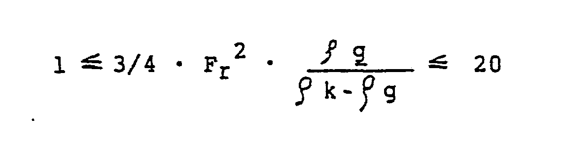
- a preferred embodiment of the invention consists in setting the vortex state in the fluidized bed in such a way that the following ranges result using the definition of the key figures of Froude and Archimedes: respectively. in which and are.
- the gas velocity in the fluidized bed reactor set to 1 to 10 m / sec (indicated as empty pipe speed).
- the average suspension density to be set in the fluidized bed reactor can vary within wide limits, for example in the range from 0.1 to 100 kg / m 3 . However, it is particularly advantageous to choose suspension densities in the lower region, since then the pressure loss when the exhaust gas passes through the fluidized bed is particularly low. An advantageous embodiment of the invention therefore provides for the average suspension density in the fluidized bed reactor to be set to 0.2 to 2 kg / m 3 .
- the amount of the hourly rotating solid to the 20- to 150-fold adjust the Feststoffmen g e located in the shaft of the fluidized bed reactor.
- the circulating fluidized bed can be formed using a fluidized bed reactor, a cyclone separator and a return line opening into the lower region of the fluidized bed reactor.
- the cyclone separator primarily serves to separate the coarse-grained solid that forms the support bed.
- the gas stream leaving the cyclone separator is subjected to a fine cleaning, e.g. by means of an electrostatic filter.
- a particularly advantageous embodiment of the invention consists in separating the solid discharged with the gases from the fluidized bed reactor in an immediately downstream electrostatic precipitator. This further reduces the pressure loss of the gas.
- the continued advantageous use of a multi-field electrostatic precipitator also gives the possibility of separating the solids discharged with the gases in a fractional manner according to the grain size and at least returning the coarser solid fraction obtained in the gas field at the front to the fluidized bed.
- the solid matter obtained in the rear field on the gas side can be discharged.
- the fluidized bed reactor used for exhaust gas purification can be of rectangular, square or circular cross section.
- a nozzle grate can be provided as the gas distributor.
- the latter training is advantageous because of the particularly low pressure drop and the susceptibility to contamination and wear.
- the solids can be introduced into the fluidized bed reactor in any conventional manner, e.g. by means of pneumatic channels. If the fine-grained solid is supplied in the form of an aqueous suspension, it is most appropriate to provide lances as the entry organs. As a result of the good cross-mixing given in circulating fluidized beds, a comparatively small number of input organs is sufficient.
- Dry cleaning can be carried out at largely any pressure, e.g. up to about 25 bar.
- An excess pressure will have to be provided in particular if the exhaust gas is already generated under excess pressure, for example because the process delivering the exhaust gas has already been operated under excess pressure.
- the exhaust gas cleaning will be carried out at a pressure of approximately 1 bar.
- the temperature of the waste gases which are to be purified by the process according to the invention is largely arbitrary, so that they can be introduced into the fluidized bed reactor practically at the same temperature at which they are obtained.
- the method according to the invention can be used universally and is particularly suitable for cleaning flue gases from power plant or waste incineration plants, exhaust gases from the secondary aluminum industry and exhaust gases from the glass and ceramic industries.
- gases can also be cleaned in gasification processes.
- sulfur oxides, hydrogen chloride, hydrogen fluoride or compounds thereof can be removed.
- the advantages of the method according to the invention are that it can be connected behind existing systems with little or no change, that it can be combined with any other form of gas purification if necessary, that gas purification can eliminate the following gas treatments and d a ß - on the unit related to the area of the fluidized bed reactor - very high exhaust gas throughputs are possible.
- gas purification can eliminate the following gas treatments and d a ß - on the unit related to the area of the fluidized bed reactor - very high exhaust gas throughputs are possible.
- the method is suitable even at large fluctuations in the pollutant content of the Agace,
- the presence of the support bed also avoids the risk of sticking or caking when the fine-grained solid serving as sorbent is added in the form of a suspension.
- the method according to the invention almost allows. full utilization of the fine-grained solid serving as sorbent and leads to purified gases with extremely favorable pollutant values.
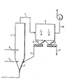
- the figure shows a schematic representation of the circulating fluidized bed.
- the exhaust gas to be cleaned is introduced into the fluidized bed reactor 2 via the conical lower part 1 provided with a Venturi nozzle.
- Coarse-grained solids are fed via line 3 as support bed material and fine-grained solids are fed as line sorbent via line 4.
- the solid / gas suspension formed leaves the fluidized bed reactor 2 via line 4 and reaches the two-field electrostatic filter 5, in which the solid is separated off.
- the coarse fraction collects in the dust bunker 6 and is returned to the fluidized bed reactor 2 via line 7.
- the fine fraction obtained in the dust bunker 8 is discharged via line 9.
- the cleaned flue gas passes through line 10 to the chimney.
- the fluidized bed reactor used had a diameter of 3.5 m and a height of 14 m in the cylindrical area.
- the exhaust gas was fed to the fluidized bed reactor 2 via the device 1 designed as a vent.
- the gas velocity in the fluidized bed reactor 2 was 5.5 m / sec, the average suspension density was approximately 0.4 kg / m 3 .
Landscapes
- Engineering & Computer Science (AREA)
- Chemical & Material Sciences (AREA)
- Environmental & Geological Engineering (AREA)
- Analytical Chemistry (AREA)
- General Chemical & Material Sciences (AREA)
- Oil, Petroleum & Natural Gas (AREA)
- Chemical Kinetics & Catalysis (AREA)
- Biomedical Technology (AREA)
- Health & Medical Sciences (AREA)
- General Engineering & Computer Science (AREA)
- Mechanical Engineering (AREA)
- Dispersion Chemistry (AREA)
- Treating Waste Gases (AREA)
- Filtering Of Dispersed Particles In Gases (AREA)
- Mechanical Treatment Of Semiconductor (AREA)
- Separation By Low-Temperature Treatments (AREA)
- Devices And Processes Conducted In The Presence Of Fluids And Solid Particles (AREA)
- Gas Separation By Absorption (AREA)
- Liquid Crystal Substances (AREA)
- Prostheses (AREA)
- Transition And Organic Metals Composition Catalysts For Addition Polymerization (AREA)
Abstract
Description
Die Erfindung betrifft ein Verfahren zur Abtrennung von Schadstoffen aus Abgasen mit Hilfe von Feststoffen in einer'aus Wirbelschichtreaktor, Abscheider und Rückführleitung gebildeten zirkulierenden Wirbelschicht.The invention relates to a method for separating pollutants from exhaust gases with the aid of solids in a circulating fluidized bed formed from a fluidized bed reactor, separator and return line.
Bei der Verbrennung fossiler Brennstoffe fallen Rauchgase an, die - je nach Schwefelgehalt der Ausgangsstoffe - beträchtliche Schwefeloxidgehalte, insbesondere Gehalte an Schwefeldioxid, aufweisen können. Auch die ständig steigende Zahl von Müllverbrennungsanlagen produziert Abgase, die neben Schwefeloxiden infolge der Verbrennung praktisch stets vorhandener Kunststoffe als weitere Verunreinigungen Chlorwasserstoff und Fluorwasserstoff enthalten. Die Umweltschutzbestimmungen verlangen, daß derartige Verunreinigungen aus den Gasen vor ihrer Ableitung in die Atmosphäre entfernt werden.When fossil fuels are burned, flue gases are produced which, depending on the sulfur content of the starting materials, can have considerable sulfur oxide contents, in particular contents of sulfur dioxide. The steadily increasing number of waste incineration plants also produces exhaust gases which, in addition to sulfur oxides, contain hydrogen chloride and hydrogen fluoride as further impurities as a result of the combustion of plastics that are practically always present. Environmental regulations require that such contaminants be removed from the gases before they are discharged into the atmosphere.
Die mit Abstand größte Zahl von Verfahren zur Abgasreinigung entfernt die vorgenannten Verunreinigungen durch Naßwäsche., wobei insbesondere Lösungen oder Aufschlämmungen von mit den Schadstoffen reagierenden Substanzen eingesetzt werden (Ullmann's Encyklopädie der Techn. Chemie, 3. Auflage, Band 2/2 (1968), Seite 419).By far the largest number of processes for exhaust gas purification remove the above-mentioned impurities by wet washing, with solutions or slurries of substances reacting with the pollutants being used in particular ( U llmann's Encyklopadie der Techn. Chemie, 3rd edition, volume 2/2 (1968) , Page 419).
Weitere Verfahren arbeiten nach dem Prinzip der sogenannten trockenen Gaswäsche. Dabei werden die Gase durch eine ruhende Schüttung von mit den Verunreinigungen reagierenden Feststoffen, wie z.B. Aktivkohle oder Braunkohlenkoks, geleitet. Die Abgasreinigung kann auch mit Hilfe einer sogenannten Wanderschicht erfolgen, bei der der Feststoff während der Abwärtsbewegung im Reaktor zunehmend beladen und schließlich ausgetragen wird. Eine dem Austrag entsprechende Menge frischen Materials wird dabei dem Reaktor im oberen Bereich aufgegeben (Meier zu Köcker "Beurteilung und Aussichten von Verfahren zur Rauchgasentschwefelung"; V.G.B. Kraftwerkstechnik 53 (1973), Seite 516 ff.).Other processes work on the principle of so-called dry gas scrubbing. The gases are released by a static bed of solids that react with the contaminants, e.g. Activated carbon or lignite coke. The exhaust gas purification can also take place with the help of a so-called traveling layer, in which the solid is increasingly loaded in the reactor during the downward movement and is finally discharged. A quantity of fresh material corresponding to the discharge is fed into the upper area of the reactor (Meier zu Köcker "Assessment and prospects of processes for flue gas desulfurization"; V.G.B. Kraftwerkstechnik 53 (1973), page 516 ff.).
Bei einem anderen bekannten Verfahren werden beispielsweise Schwefeloxide aus Gasen entfernt, indem man in diese pneumatisch Adsorbentien einträgt, die so erhaltene Gas/Feststoff-Dispersion pneumatisch durch eine Reaktionsstrecke und dann durch eine Verweilzone leitet und danach den Feststoff vom Gas trennt. Nach-bestimmten Regeneriermaßnahmen wird letztlich ein Feststoffteilstrom zur Gasreinigung zurückgeführt (US-PS 3 485 014).In another known process, for example, sulfur oxides are removed from gases by pneumatically introducing them into adsorbents, pneumatically passing the gas / solids dispersion thus obtained through a reaction zone and then through a residence zone and then separating the solids from the gas. After certain regeneration measures, a partial solids stream is ultimately returned for gas purification (US Pat. No. 3,485,014).
Schließlich ist eine Einrichtung zur trockenen Entfernung von Schadstoffen aus Rauchgasen bekannt, die in Abzugsrichtung hinter dem Verbrennungsbereich in einem Kesselbereich mit einer Rauchgastemperatur von 700 bis 900 °C arbeitet. Sie weist ein den Rauchgasquerschnitt vollständig ausfüllendes Wirbelbett und/oder eine zirkulierende Wirbelschicht, die z.B. mit Calcium- und/oder Magnesiumcarbonat als Absorptionsmittel beaufschlagt ist, auf (DE-DS 30 09 366). Dabei wird der Anströmboden des Wirbelbettes zweckmäßigerweise gekühlt.Finally, a device for the dry removal of pollutants from flue gases is known, which works in the exhaust direction behind the combustion area in a boiler area with a flue gas temperature of 700 to 900 ° C. It has a fluidized bed that completely fills the flue gas cross-section and / or a circulating fluidized bed that e.g. with calcium and / or magnesium carbonate as the absorbent, on (DE-DS 30 09 366). The inflow floor of the fluidized bed is expediently cooled.
Die wesentlichen Nachteile der Naßreinigungsverfahren sind, daß der anfallende-Sulfite und Sulfate, gegebenenfalls auch Chloride und Fluoride enthaltende Schlamm nur schwierig deponierbar ist und daß die gereinigten Abgase erneut aufgeheizt werden müssen. Die bekannten Trockenreinigungsverfahren mit stationärem oder Wanderbett sind insofern mit Nachteilen behaftet, als wegen der Grobkörnigkeit der Absorbentien das Bindevermögen für die im Abgas enthaltenen Verunreinigungen nur sehr unvollkommen ausgenutzt wird und wegen der vergleichsweise geringen zulässigen Gasgeschwindigkeit sowie der großen zu reinigenden Gasmengen beträchtliche Reaktorabmessungen erforderlich sind.The main disadvantages of the wet cleaning process are that the resulting sludge, which contains sulfites and sulfates, and possibly also chlorides and fluorides, is difficult to deposit and that the cleaned exhaust gases are heated again Need to become. The known dry cleaning methods with a stationary or moving bed have disadvantages in that, because of the coarseness of the absorbents, the binding capacity for the impurities contained in the exhaust gas is used only very incompletely, and considerable reactor dimensions are required because of the comparatively low permissible gas speed and the large gas quantities to be cleaned.
Die wesentlichen Nachteile des Verfahrens gemäß US-PS 3 485 014 liegen in dem Erfordernis, eine Aufteilung des zu reinigenden Gasstromes sowie eine präzise Dosierung des Absorptionsmittels in einer geeigneten, insbesondere verschleißfesten Vorrichtung vornehmen zu müssen. Nachteilig ist auch die für eine hinreichende Entfernung der Verunreinigungen ungenügend lange Verweilzeit der Gase in der Reaktionsstrecke oder aber die sonst erforderliche beträchtliche,Bauhöhe.The main disadvantages of the method according to US Pat. No. 3,485,014 lie in the need to have to divide the gas stream to be cleaned and to precisely meter the absorbent in a suitable, in particular wear-resistant, device. Another disadvantage is the insufficiently long residence time of the gases in the reaction zone for a sufficient removal of the impurities or the considerable structural height that is otherwise required.
Die Entfernung von Schadstoffen aus Rauchgasen von 700 bis 900 °C gemäß DE-OS 30 09 366 bereitet insofern Schwierigkeiten, als es besonderer Maßnahmen und Eingriffe in die Verbrennungsanlage bedarf, um die Temperatur der Rauchgase, die beim Austritt aus dem Brennraum üblicherweise heißer und beim Austritt aus dem Abhitzekessel üblicherweise kälter sind, aufeinen-Wert im Bereich von 700 bis 900 °c einzustellen.The removal of pollutants from flue gases from 700 to 900 ° C according to DE-OS 30 09 366 presents difficulties insofar as special measures and interventions in the incineration system are required to control the temperature of the flue gases, which are usually hotter and when they exit the combustion chamber Outlet from the waste heat boiler are usually colder, set to a value in the range of 700 to 900 ° C.
Bei einem Spezialproblem, nämlich der Entfernung von Fluorwasserstoff aus Abgasen., insbesondere Abgasen der Aluminiumelektrolyse, ist es bekannt, die Fluorwasserstoff enthaltenden Gase als Fluidisierungsgas-in einen Wirbelschichtreaktor zu leiten und dabei die Fluidisierungsgasgeschwindigkeit derart einzustellen, daß sich eine über den Wirbelschichtreaktor, einen nachgeschalteten Zyklonabscheider und eine Rückführleitung fließende zirkulierende Wirbelschicht ausbilden kann (DE-OS 20 56 096). Als Feststoffe zur Ausbildung der zirkulie-.. renden Wirbelschicht sind Aluminiumoxid und/oder Natriumaluminat erwähnt, die nach hinreichend hoher Beladung in die Schmelzflußelektrolyse zurückgeführt werden.In the case of a special problem, namely the removal of hydrogen fluoride from waste gases, in particular waste gases from aluminum electrolysis, it is known to pass the gases containing hydrogen fluoride as fluidizing gas into a fluidized bed reactor and to adjust the fluidizing gas velocity in such a way that one downstream of the fluidized bed reactor Cyclone separator and a return line can form flowing circulating fluidized bed (DE-OS 20 56 096). Aluminum oxide and / or sodium aluminum are the solids for forming the circulating fluidized bed minat mentioned, which are returned to the melt flow electrolysis after a sufficiently high load.
Das Wesen des vorgenannten Verfahrens besteht nicht nur in der Reinigung spezieller Abgase, sondern von seiner Zielsetzung her insbesondere auch darin, das im Abgas enthaltene Fluor in einer Form zu gewinnen, die es gestattet, es in die Schmelzflußelektrolyse zurückzuleiten und dadurch den Fluorbedarf zu reduzieren. Bei der Abgasrein-igung hingegen ist eine Rückgewinnung von Schwefeloxiden bzw. anderen Schadstoffen in der Regel nicht beabsichtigt. Statt dessen wird das beladene Sorptionsmittel z.B. für Bauzwecke oder als Versatzmaterial genutzt ggf. auch verworfen.The essence of the aforementioned method is not only the purification of special exhaust gases, but also its objective, in particular, to recover the fluorine contained in the exhaust gas in a form that allows it to be returned to the melt flow electrolysis and thereby reduce the fluorine requirement. In contrast, exhaust gas cleaning is generally not intended to recover sulfur oxides or other pollutants. Instead, the loaded sorbent is e.g. used for construction purposes or as backing material, possibly discarded.
Aufgabe der Erfindung ist es, ein Verfahren bereitzustellen, das die Nachteile der bekannten Gasreinigungsverfahren nicht aufweist, einfach in der Durchführung ist und sich billigster Absorptionsmittel bedlienen kann.The object of the invention is to provide a method which does not have the disadvantages of the known gas purification methods, is simple to carry out and can use the cheapest absorption means.
Die Aufgabe wird gelöst, indem das Verfahren der eingangs genannten Art entsprechend der Erfindung derart ausgestaltet wird, daß man das Abgas als Fluidisierungsgas in eine aus zwei Feststoffen unterschiedlicher Körnung gebildete Wirbelschicht einleitet, von denen der gröbere Feststoff eine Körnung von dp 50 im Bereich von 150 bis 500 um und der feine Feststoff eine Körnung von dp 50 unterhalb 10 µm aufweisen.The object is achieved by designing the method of the type mentioned at the outset in accordance with the invention in such a way that the exhaust gas is introduced as fluidizing gas into a fluidized bed formed from two solids of different grain sizes, of which the coarser solid has a grain size of d p 50 in the range from 150 to 500 µm and the fine solid have a grain size of dp 50 below 10 µm.
Das erfindungswesentliche Merkmal des Einsatzes zweier Feststoffe mit unterschiedlicher Körnung bewirkt, daß die Verweil- zeit des feinkörnigen Feststoffes, der sonst - ähnlich wie bei. einer pneumatischen Förderung - unverzüglich mit entsprechend schlechteren Bedingungen hinsichtlich Wärme- und Stoffübertragung ausgetragen würde, innerhalb des Wirbelschichtreaktors beträchtlich erhöht wird. Darüber hinaus ist aufgrund des vergleichsweise groben Kornspektrums des Stützbettmaterials eine große Relativbewegung zwischen Grob- und Feinkorn zu erreichen. Hierdurch wirdThe essential feature of the invention, the use of two materials effects with different grain size that the V erweil- time of the fine-grained solid which otherwise - similar. pneumatic conveyance - would immediately be carried out with correspondingly poorer conditions with regard to heat and mass transfer, will be considerably increased within the fluidized bed reactor. In addition, due to the comparatively coarse grain spectrum of the support bed material, a large relative movement between coarse and fine grains can be achieved. This will
ein mechanischer Abrieb der bereits durch Sorption besetzten Oberfläche des Feinkorns erzielt und zur Sorption befähigte Oberfläche neu geschaffen.mechanical abrasion of the surface of the fine grain already occupied by sorption is achieved and a surface capable of sorption is newly created.
Das bei der Erfindung angewendete Prinzip der expandierten Wirbelschicht zeichnet sich dadurch aus, daß - im Unterschied zur "klassischen" Wirbelschicht, bei der eine dichte Phase durch einen deutlichen Dichtesprung von dem darüber befindlichen Gasraum getrennt ist - Verteilungszustände ohne definierte Grenzschicht vorliegen. Ein Dichtesprung zwischen dichter Phase und dem darüber befindlichen Staubraum ist nicht vorhanden, statt dessen nimmt innerhalb des Reaktors die Feststoffkonzentration von unten nach oben ab.The principle of the expanded fluidized bed used in the invention is characterized in that - in contrast to the "classic" fluidized bed in which a dense phase is separated from the gas space above it by a clear density jump - there are distribution states without a defined boundary layer. There is no jump in density between the dense phase and the dust space above it, instead the solid concentration within the reactor decreases from bottom to top.
Der ein Stützbett bildende gröbere Feststoff kann vorzugsweiseaus Calciumoxid, Calciumhydroxid; Calciumcarbonat,Dolomit, Magnesiumoxid oder Magnesiumcarbonat, aber auch aus inerten Stoffen, wie z.B. aus Sand, bestehen. Dessen Fähigkeit zur sorptiven Bindung der Schadstoffe ist-von untergeordneter Bedeutung:
- Der feinkörnige Feststoff, der primär die Sorption der Schadstoffe zu bewirken hat, kann aus den vorgenannten Materialien, mit Ausnahme von'Sand, bestehen. Bevorzugt angewendet wird Calciumhydroxid. Es können aber auch insoweit geeignete Ab-fallprodukte, wie z.B. der bei der Aluminiumoxidhydraterzeugung anfallende Rotschlamm, eingesetzt werden.
- The fine-grained solid, which is primarily responsible for the sorption of the pollutants, can consist of the aforementioned materials, with the exception of sand. Calcium hydroxide is preferably used. But it can also extent suitable A b-fall products, such as are used, for example, the obtained in the Aluminiumoxidhydraterzeugung red mud.
Der feinkörnige Feststoff kann im Wirbelschichtreaktor sowohl in fester Form als auch in Form einer wäßrigen Suspension aufgegeben werden.The fine-grained solid can be introduced in the fluidized bed reactor both in solid form and in the form of an aqueous suspension.
Gemäß einer bevorzugten Ausgestaltung der Erfindung sollte in der Wirbelschicht der Anteil an grobem Feststoff auf 70 bis 90 Gew.-% und an feinem Feststoff auf 10 bis 30 Gew.-% eingestellt werden.According to a preferred embodiment of the invention, the proportion of coarse solids to 70 to 90 G ew .-%, and the fine solid material to 10 to 30 wt .-% should be set in the fluidized bed.
Eine bevorzugte Ausgestaltung der Erfindung besteht darin, den Wirbelzustand in der Wirbelschicht derart einzustellen, daß sich ünter Verwendung der Definition über die Kennzahlen von Froude und Archimedes folgende Bereiche ergeben:


Hierbei bedeuten:
- u die relative Gasgeschwindigkeit in m/sec
- Ar die Archimedeszahl
- Fr die Froude-Zahl
- g die Dichte des Gases in kg/m

- fk die Dichte des Feststoffteilchens in kg/m
- dk den Durchmesser des kugelförmigen Teilchens in m
- die kinematische Zähigkeit in m2/sec

- g die Gravitationskonstante in m/sec2.
- u the relative gas velocity in m / sec
- Ar is the Archimedes number
- For the Froude number
- g is the density of the gas in kg / m
- f k is the density of the solid particle in kg / m
- d k is the diameter of the spherical particle in m
- the kinematic toughness in m 2 / sec
- g is the gravitational constant in m / sec 2 .
Hinsichtlich Durchsatzleistung von Abgas und Grad der Schad- stoffentfernung infolge guter Feststoff/Gas-Vermischung ist es zweckmäßig, daß man die Gasgeschwindigkeit im Wirbelschichtreaktor auf 1 bis 10 m/sec (angegeben als Leerrohrgeschwindigkeit) einstellt.With regard to throughput of exhaust and the degree of S material removing chad- due to good solid / gas mixing, it is expedient that the gas velocity in the fluidized bed reactor set to 1 to 10 m / sec (indicated as empty pipe speed).
Die im Wirbelschichtreaktor einzustellende mittlere Suspensionsdichte kann in weiten Grenzen, z.B. im Bereich von 0,1 bis 100 kg/m3, variieren. Besonders vorteilhaft ist es jedoch, Suspensionsdichten im unteren Bereich zu wählen, da dann der Druckverlust beim Durchgang des Abgases durch-das Wirbelbett besonders niedrig ist. Eine vorteilhafte Ausgestaltung der Erfindung sieht daher vor, die mittlere Suspensionsdichte im Wirbelschichtreaktor auf 0,2 bis 2 kg/m3 einzustellen.The average suspension density to be set in the fluidized bed reactor can vary within wide limits, for example in the range from 0.1 to 100 kg / m 3 . However, it is particularly advantageous to choose suspension densities in the lower region, since then the pressure loss when the exhaust gas passes through the fluidized bed is particularly low. An advantageous embodiment of the invention therefore provides for the average suspension density in the fluidized bed reactor to be set to 0.2 to 2 kg / m 3 .
Um eine möglichst hohe Beladung des Sorptionsmittels mit den im-Abgas enthaltenen Verunreinigungen sowie eine möglichst optimale Feststoff/Gas-Vermischung zu erzielen; sieht eine weitere vorteilhafte Ausgestaltung der Erfindung vor, die Menge des stündlich umlaufenden Feststoffes auf das 20- bis 150-fache der im Schacht des Wirbelschichtreaktors befindlichen Feststoffmenge einzustellen.In order to achieve the highest possible loading of the sorbent with the impurities contained in the exhaust gas and the best possible solid / gas mixing; provides a further advantageous embodiment of the invention, the amount of the hourly rotating solid to the 20- to 150-fold adjust the Feststoffmen g e located in the shaft of the fluidized bed reactor.
Die zirkulierende Wirbelschicht kann unter Verwendung eines Wirbelschichtreaktors, eines Zyklonabscheiders und einer in den unteren Bereich des Wirbelschichtreaktors mündenden Rückführleitung gebildet werden. Hierbei dient der Zyklonabscheider primär der Abtrennung des das Stützbett bildenden grobkörnigen Feststoffes. Für die Entfernung der Feinanteile wird der den Zyklonabscheider verlassende Gasstrom einer Feinreinigung, z.B. mittels eines Elektrofilters, unterworfen.The circulating fluidized bed can be formed using a fluidized bed reactor, a cyclone separator and a return line opening into the lower region of the fluidized bed reactor. Here, the cyclone separator primarily serves to separate the coarse-grained solid that forms the support bed. To remove the fine particles, the gas stream leaving the cyclone separator is subjected to a fine cleaning, e.g. by means of an electrostatic filter.
Eine besonders vorteilhafte Ausgestaltung der Erfindung besteht jedoch darin, die Abscheidung des mit den Gasen aus dem Wirbelschichtreaktor ausgetragenen Feststoffes in einem unmittelbar nachgeschalteten Elektrofilter vorzunehmen. Hierdurch wird der Druckverlust des Gases zusätzlich verringert.A particularly advantageous embodiment of the invention, however, consists in separating the solid discharged with the gases from the fluidized bed reactor in an immediately downstream electrostatic precipitator. This further reduces the pressure loss of the gas.
Die weiterhin vorteilhafte Verwendung eines me.hrfeldrigen Elektrofilters gibt zudem die Möglichkeit, die mit den Gasen ausgetragenen Feststoffe nach der Korngröße fraktioniert abzuscheiden und mindestens die im gasseitig vorderen Feld erhaltene gröbere Feststofffraktion in die Wirbelschicht zurückzuführen. Der im gasseitig hinteren Feld erhaltene Feststoff - kann ausgeschleust werden.The continued advantageous use of a multi-field electrostatic precipitator also gives the possibility of separating the solids discharged with the gases in a fractional manner according to the grain size and at least returning the coarser solid fraction obtained in the gas field at the front to the fluidized bed. The solid matter obtained in the rear field on the gas side can be discharged.
Der der Abgasreinigung dienende Wirbelschichtreaktor kann von rechteckigem, quadratischem oder kreisförmigem Querschnitt sein. Als Gasverteiler kann ein Düsenrost vorgesehen werden. Insbesondere bei großen Reaktorquerschnitten und hohen Gasdurchsätzen ist es jedoch vorteilhaft, den unteren Bereich des Wirbelschichtreaktors konisch auszubilden und das Abgas durch eine venturiähnliche Düse einzutragen. Die letztgenannte Ausbildung ist wegen des besonders niedrigen Druckverlustes und der Unanfälligkeit gegenüber Verschmutzung und Verschleiß von Vorteil.The fluidized bed reactor used for exhaust gas purification can be of rectangular, square or circular cross section. A nozzle grate can be provided as the gas distributor. Particularly in the case of large reactor cross sections and high gas throughputs, however, it is advantageous to make the lower region of the fluidized bed reactor conical and to introduce the exhaust gas through a venturi-like nozzle. The latter training is advantageous because of the particularly low pressure drop and the susceptibility to contamination and wear.
Der Eintrag der Feststoffe in den Wirbelschichtreaktor kann auf jede übliche Weise, z.B. durch pneumatische Rinnen, erfolgen. Sofern der feinkörnige Feststoff in Form einer wäßrigen Suspension zugeführt wird, sind als Eintragsorgane am zweckmäßigsten Lanzen vorzusehen. Infolge der bei zirkulierenden Wirbelschichten gegebenen guten Quervermischung reicht eine vergleichsweise geringe Zahl von Eintragsorganen.The solids can be introduced into the fluidized bed reactor in any conventional manner, e.g. by means of pneumatic channels. If the fine-grained solid is supplied in the form of an aqueous suspension, it is most appropriate to provide lances as the entry organs. As a result of the good cross-mixing given in circulating fluidized beds, a comparatively small number of input organs is sufficient.
Die Trockenreinigung kann bei weitgehend beliebigen Drücken, z.B. bis etwa 25 bar, vorgenommen werden. Ein Überdruck wird insbesondere dann vorzusehen sein, wenn das Abgas bereits unter Überdruck anfällt, beispielsweise weil der das Abgas liefernde Prozeß bereits unter Überdruck betrieben worden ist. Im allgemeinen wird man jedoch die Abgasreinigung bei einem Druck um ca. 1 bar vornehmen.Dry cleaning can be carried out at largely any pressure, e.g. up to about 25 bar. An excess pressure will have to be provided in particular if the exhaust gas is already generated under excess pressure, for example because the process delivering the exhaust gas has already been operated under excess pressure. In general, however, the exhaust gas cleaning will be carried out at a pressure of approximately 1 bar.
Die Temperatur der Abgase, die nach dem erfindungsgemäßen Verfahren gereinigt werden sollen, ist weitgehend beliebig, so daß sie praktisch mit der gleichen Temperatur, mit der sie anfallen, in den Wirbelschichtreaktor eingetragen werden können. Um für die Eintragsorgane in den Wirbelschichtreaktor auf hitzebeständigen Materialien oder spezielle Kühlsysteme für die Eintragsvorrichtung verzichten zu können, ist es zweckmäßig, nicht bei Temperaturen oberhalb 550 0C zu arbeiten.The temperature of the waste gases which are to be purified by the process according to the invention is largely arbitrary, so that they can be introduced into the fluidized bed reactor practically at the same temperature at which they are obtained. In order to be able to dispense with heat-resistant materials or special cooling systems for the feed device for the feed elements in the fluidized bed reactor, it is advisable not to work at temperatures above 550 ° C.
Mit Hilfe des erfindungsgemäßen Verfahrens kann das gesamte anfallende Abgas, gegebenenfalls nur ein Teilstrom, gereinigt werden. Auch ist es möglich, das erfindungsgemäße Verfahren in Kombination mit Naßreinigungsverfahren durchzuführen. Diese Parallelschaltung hat den Vorteil, daß die bei Naßreinigungsverfahren praktisch unerläßliche Wiederaufheizung der gereinigten Gase zur Vermeidung einer Taupunktunterschreitung oder einer Kaminfahne unterbleiben kann.With the aid of the method according to the invention, all of the waste gas obtained, possibly only a partial stream, can be cleaned. It is also possible to carry out the method according to the invention in combination with wet cleaning methods. This parallel connection has the advantage that the practically indispensable reheating of the cleaned gases in wet cleaning processes can be avoided in order to avoid falling below a dew point or a chimney flue.
Das erfindungsgemäße Verfahren ist universell anwendbar und insbesondere für die Reinigung von Rauchgasen aus Kraftwerks- oder Müllverbrennungsanlagen, von Abgasen der Sekundär-Aluminiumindustrie und von Abgasen der Glas- und Keramikindustrie-geeignet. Mit dem erfindungsgemäßen Verfahren können auch Gase in Vergasungsprozessen gereinigt werden. Insbeson- dere können Schwefeloxide, Chlorwasserstoff, Fluorwasserstoff oder Verbindungen hiervon entfernt werden.The method according to the invention can be used universally and is particularly suitable for cleaning flue gases from power plant or waste incineration plants, exhaust gases from the secondary aluminum industry and exhaust gases from the glass and ceramic industries. With the method according to the invention, gases can also be cleaned in gasification processes. In particular, sulfur oxides, hydrogen chloride, hydrogen fluoride or compounds thereof can be removed.
Die Vorteile des erfindungsgemäßen Verfahrens sind, daß es ohne oder nur unbedeutende Veränderung hinter bestehende Anlagen geschaltet werden kann, daß es im Bedarfsfall mit jeder anderen Form der Gasreinigung kombiniert werden kann, daß der Gasreinigung folgende Gasbehandlungen entfallen können und daß - auf die Einheit der Fläche des Wirbelschichtreaktors bezogen - sehr hohe Abgasdurchsätze möglich sind. Infolge der . hohen in der zirkulierenden Wirbelschicht umlaufenden Sorp- tionsmittelmenge, die eine beträchtliche Pufferwirkung ausübt, ist das Verfahren geeignet, selbst bei starken Schwankungen im Schadstoffgehalt der Agace, ![]()
![]()
Aufwand eine sichere Gasreinigung herbeizuführen. Durch das Vorhandensein des Stützbettes wird bei Aufgabe des feinkörnigen, als Sorptionsmittel dienenden Feststoffes in Form einer Suspension zudem eine Verklebungs- oder Anbackungsgefahr vermieden. Das erfindungsgemäße Verfahren erlaubt eine nahezu . vollständige Ausnutzung des als Sorptionsmittel dienenden feinkörnigen Feststoffes und führt zu gereinigten Gasen mit extrem günstigen Schadstoffenwerten.Effort to achieve a safe gas cleaning. The presence of the support bed also avoids the risk of sticking or caking when the fine-grained solid serving as sorbent is added in the form of a suspension. The method according to the invention almost allows. full utilization of the fine-grained solid serving as sorbent and leads to purified gases with extremely favorable pollutant values.
Die Erfindung wird anhand der Figur und des Beispiels näher und beispielsweise erläutert.The invention is explained in more detail and, for example, using the figure and the example.
Die Figur zeigt eine schematische Darstellung der zirkulierenden Wirbelschicht.The figure shows a schematic representation of the circulating fluidized bed.
Das zu reinigende Abgas wird über das konisch ausgebildete und mit einer Venturidüse versehene Unterteil 1 in den Wirbelschichtreaktor 2 eingetragen. Über Leitung 3 wird-grobkörniger Feststoff-als Stützbettmaterial und über Leitung 4 feinkörniger Feststoff als Sorptionsmittel zugeführt. Die gebildete Feststoff/Gas-Suspension verläßt den Wirbelschichtreaktor 2 über Leitung 4 und gelangt in das zweifeldrige Elektrofilter 5, in dem den Feststoff abgeschieden wird. Die Grobfraktion sammelt sich im Staubbunker 6 und wird über Leitung 7 in den Wirbelschichtreaktor 2 zurückgeführt. Die im Staubbunker 8 anfallende Feinfraktion wird über Leitung 9 ausgetragen. Das gereinigte Rauchgas gelangt über Leitung 10 zum Kamin.The exhaust gas to be cleaned is introduced into the fluidized bed reactor 2 via the conical lower part 1 provided with a Venturi nozzle. Coarse-grained solids are fed via line 3 as support bed material and fine-grained solids are fed as line sorbent via line 4. The solid / gas suspension formed leaves the fluidized bed reactor 2 via line 4 and reaches the two-field
Zu reinigen war ein Abgas einer Müllverbrennungsanlage, das mit 220 °C in einer Menge von 100 000 m3/h (im Normzu- stand) anfiel. Das Abgas enthielt (bezogen auf den Normzustand)

Das Abgas wurde über die venturimäßig ausgestaltete Vorrichtung 1 dem Wirbelschichtreaktor 2 zugeführt. Uber Leitung 3 wurde Dolomit mit einer Körnung von dp 50 = 250 /um in einer Menge von 0,36 kg/h und über Leitung 4 Calciumhydroxid mit einer Körnung dp 50 = 8 µm in einer Menge von 360 kg/h zudosiert.The exhaust gas was fed to the fluidized bed reactor 2 via the device 1 designed as a vent. Via line 3 was = 250 / um in an amount of 0.36 kg / h via line 4 calcium hydroxide with a grain size dp 50 = 8 microns in an amount of 360 kg / metered dolomite having a grain size of d p 50 h.
Die Gasgeschwindigkeit im Wirbelschichtreaktor 2 betrug 5,5 m/sec, die mittlere Suspensionsdichte ca. 0,4 kg/m3.The gas velocity in the fluidized bed reactor 2 was 5.5 m / sec, the average suspension density was approximately 0.4 kg / m 3 .
Die am Kopf des Wirbelschichtreaktors 2 über Leitung 4 austretende Feststoff/Gas-Suspension, die eine Suspensionsdichte von 400 g/m3 (im Normzustand) besaß, gelangte dann in das zweifeldrige Elektrofilter 5. Im Staubbunker 6 fielen stündlich 39,12 t Feststoff, die komplett über-Leitung 7 in den unteren Bereich des Wirbelschichtreaktors 2 zurückgeführt wurden, an. Über den Staubbunker 8 erfolgte der Austrag von stündlich insgesamt 872 kg Feststoff.. Dieser bestand aus einem Gemisch von Asche, die mit den Verbrennungsgasen der Müllverbrennungsanlage eingetragen worden waren, sowie insbesondere aus Calciumchlorid, Calciumfluorid, Calciumsulfat, Caiciumsulfit sowie unumgesetztem Dolomit und unumgesetztes Calciumhydroxid.The solid / gas suspension emerging at the head of the fluidized bed reactor 2 via line 4 and having a suspension density of 400 g / m 3 (in the normal state) then passed into the two-field
Das über die Leitung 10 abgeführte Abgas enthielt - jeweils auf einen Normalkubikmeter bezogen--

Claims (11)
Priority Applications (1)
| Application Number | Priority Date | Filing Date | Title |
|---|---|---|---|
| AT83201313T ATE22399T1 (en) | 1982-09-25 | 1983-09-13 | PROCESS FOR SEPARATION OF POLLUTANTS FROM EXHAUST GASES. |
Applications Claiming Priority (2)
| Application Number | Priority Date | Filing Date | Title |
|---|---|---|---|
| DE19823235558 DE3235558A1 (en) | 1982-09-25 | 1982-09-25 | METHOD FOR SEPARATING POLLUTANTS FROM EXHAUST GAS |
| DE3235558 | 1982-09-25 |
Publications (2)
| Publication Number | Publication Date |
|---|---|
| EP0105547A1 true EP0105547A1 (en) | 1984-04-18 |
| EP0105547B1 EP0105547B1 (en) | 1986-09-24 |
Family
ID=6174151
Family Applications (1)
| Application Number | Title | Priority Date | Filing Date |
|---|---|---|---|
| EP83201313A Expired EP0105547B1 (en) | 1982-09-25 | 1983-09-13 | Process for separating noxious material from off-gases |
Country Status (11)
| Country | Link |
|---|---|
| US (1) | US4548797A (en) |
| EP (1) | EP0105547B1 (en) |
| JP (1) | JPS5966332A (en) |
| AT (1) | ATE22399T1 (en) |
| AU (1) | AU557638B2 (en) |
| CA (1) | CA1212824A (en) |
| DE (2) | DE3235558A1 (en) |
| DK (1) | DK163867C (en) |
| ES (1) | ES8405637A1 (en) |
| GR (1) | GR79727B (en) |
| NO (1) | NO159244C (en) |
Cited By (8)
| Publication number | Priority date | Publication date | Assignee | Title |
|---|---|---|---|---|
| EP0172588A2 (en) * | 1984-08-09 | 1986-02-26 | Metallgesellschaft Ag | Process for separating NOx and SO2 from flue gases |
| FR2574308A1 (en) * | 1984-12-07 | 1986-06-13 | Inst Francais Du Petrole | METHOD AND DEVICE FOR GENERATING HEAT AND REALIZING DESULFURIZATION OF COMBUSTION GASES |
| FR2575272A1 (en) * | 1984-12-20 | 1986-06-27 | Fives Cail Babcock | Flue gas desulphurisation |
| EP0228111A1 (en) * | 1985-12-18 | 1987-07-08 | Metallgesellschaft Ag | Process for the removal of noxious matter from waste gases |
| EP0292083A2 (en) * | 1987-05-18 | 1988-11-23 | Roland Fichtel | Method of producing reactive calcium hydroxides for gas and exhaust gas purification, and method of purifying gases and exhaust gases |
| CH669028A5 (en) * | 1987-07-07 | 1989-02-15 | Sulzer Ag | Flue gas system with particle separator - returns carbon rich particles to fluidised bed of boiler |
| EP0331244A1 (en) * | 1988-03-03 | 1989-09-06 | Metallgesellschaft Ag | Process for the continuous dry-slaking of lime |
| WO1997033678A1 (en) * | 1996-03-11 | 1997-09-18 | Fls Miljø A/S | A method for removing nitrogen oxides, sulfur oxides, and other acid gases from a gas stream |
Families Citing this family (45)
| Publication number | Priority date | Publication date | Assignee | Title |
|---|---|---|---|---|
| US4734272A (en) * | 1984-07-27 | 1988-03-29 | Wilson Sr Eddie K | Phospho-gypsum recovery process |
| CA1289728C (en) * | 1984-07-30 | 1991-10-01 | Mitsuhiro Horaguchi | Method for treating exhaust gas |
| DE3526008A1 (en) * | 1985-07-20 | 1987-01-22 | Metallgesellschaft Ag | METHOD FOR REMOVING POLLUTANTS FROM SMOKE GAS |
| US4726940A (en) * | 1986-05-21 | 1988-02-23 | Hitachi Zosen Corporation | Method of purifying exhaust gas |
| US4917875A (en) * | 1986-05-27 | 1990-04-17 | Englehard Corporation | Gas/solid contact method for removing sulfur oxides from gases |
| DE3629817A1 (en) * | 1986-09-02 | 1988-03-03 | Bergwerksverband Gmbh | METHOD FOR REDUCING POLLUTANT EMISSIONS FROM POWER PLANTS WITH COMBINED GAS / STEAM TURBINE PROCESSES WITH UPstream CARBON GASIFICATION |
| US5306475A (en) * | 1987-05-18 | 1994-04-26 | Ftu Gmbh Technische Entwicklung Und Forschung Im Umweltschutz | Reactive calcium hydroxides |
| US5213587A (en) * | 1987-10-02 | 1993-05-25 | Studsvik Ab | Refining of raw gas |
| FR2664022B1 (en) * | 1990-06-28 | 1995-06-16 | Inst Francais Du Petrole | METHOD AND DEVICE FOR GENERATING HEAT COMPRISING DESULFURIZATION OF EFFLUENTS WITH FINE SIZE ABSORBENT PARTICLES IN A TRANSPORTED BED. |
| DE4034498A1 (en) * | 1990-09-06 | 1992-03-12 | Metallgesellschaft Ag | METHOD FOR SEPARATING HEAVY METALS AND DIOXINES FROM COMBUSTION EXHAUST GASES |
| DE4039213C2 (en) * | 1990-12-08 | 1994-02-03 | Metallgesellschaft Ag | Method and device for dedusting, desulfurizing and denitrifying combustion gases |
| DE4206602C2 (en) * | 1992-03-03 | 1995-10-26 | Metallgesellschaft Ag | Process for removing pollutants from combustion exhaust gases and fluidized bed reactor therefor |
| US5500195A (en) * | 1992-11-13 | 1996-03-19 | Foster Wheeler Energy Corporation | Method for reducing gaseous emission of halogen compounds in a fluidized bed reactor |
| US5464597A (en) * | 1994-02-18 | 1995-11-07 | Foster Wheeler Energy Corporation | Method for cleaning and cooling synthesized gas |
| DE4413280C2 (en) * | 1994-04-16 | 1997-08-21 | Metallgesellschaft Ag | Method and device for separating dioxins and furans from the exhaust gas of a sintering process |
| DE4429027C2 (en) * | 1994-08-16 | 1997-09-11 | Metallgesellschaft Ag | Process for the separation of polycyclic and polyhalogenated hydrocarbons, in particular dioxins and furans, from the exhaust gas of a sintering process |
| AT401890B (en) * | 1994-11-10 | 1996-12-27 | Scheuch Alois Gmbh | Process and plant for cleaning pollutant-loaded gases, especially flue gases |
| IT1289574B1 (en) * | 1995-04-07 | 1998-10-15 | Danieli Off Mecc | PROCEDURE FOR THE REMOVAL OF ORGAN-HALOGENATED MOLECULES FROM GASEOUS CURRENTS AND RELATED SYSTEM |
| DE19517863C2 (en) * | 1995-05-16 | 1998-10-22 | Metallgesellschaft Ag | Process for dry desulfurization of a combustion exhaust gas |
| AU710611B2 (en) * | 1995-12-05 | 1999-09-23 | Metallgesellschaft Aktiengesellschaft | Process and apparatus for separating polycyclic and polyhalogenated hydrocarbons from exhaust gas of a sintering process |
| US5990373A (en) * | 1996-08-20 | 1999-11-23 | Kansas State University Research Foundation | Nanometer sized metal oxide particles for ambient temperature adsorption of toxic chemicals |
| US5997823A (en) * | 1997-08-18 | 1999-12-07 | Noxso Corporation | Processes and apparatus for removing acid gases from flue gas |
| US6093236A (en) * | 1998-05-30 | 2000-07-25 | Kansas State University Research Foundation | Porous pellet adsorbents fabricated from nanocrystals |
| US6057488A (en) * | 1998-09-15 | 2000-05-02 | Nantek, Inc. | Nanoparticles for the destructive sorption of biological and chemical contaminants |
| US6417423B1 (en) | 1998-09-15 | 2002-07-09 | Nanoscale Materials, Inc. | Reactive nanoparticles as destructive adsorbents for biological and chemical contamination |
| US6653519B2 (en) * | 1998-09-15 | 2003-11-25 | Nanoscale Materials, Inc. | Reactive nanoparticles as destructive adsorbents for biological and chemical contamination |
| DE10133991B4 (en) * | 2001-07-12 | 2012-08-02 | Doosan Lentjes Gmbh | Apparatus for purifying combustion exhaust gases |
| SE523667C2 (en) * | 2002-09-20 | 2004-05-11 | Alstom Switzerland Ltd | Method and apparatus for separating gaseous pollutants from hot gases by particulate absorbent material and mixer for wetting the absorbent material |
| US7658788B2 (en) * | 2003-08-06 | 2010-02-09 | Air Products And Chemicals, Inc. | Ion transport membrane module and vessel system with directed internal gas flow |
| US7179323B2 (en) * | 2003-08-06 | 2007-02-20 | Air Products And Chemicals, Inc. | Ion transport membrane module and vessel system |
| US7425231B2 (en) * | 2003-08-06 | 2008-09-16 | Air Products And Chemicals, Inc. | Feed gas contaminant removal in ion transport membrane systems |
| US20080159922A1 (en) * | 2004-09-22 | 2008-07-03 | Lurgi Lent Jes Ag | Flue-Gas Purification System |
| US7771519B2 (en) * | 2005-01-03 | 2010-08-10 | Air Products And Chemicals, Inc. | Liners for ion transport membrane systems |
| JP5688790B2 (en) * | 2010-03-08 | 2015-03-25 | 株式会社 日本リモナイト | Desulfurization equipment |
| KR101015154B1 (en) * | 2010-10-05 | 2011-02-16 | 한국에너지기술연구원 | Adsorbent internal and external circulating device and their methods for treatment of high temperature flue gases containing sulfur oxides and boron compounds |
| CN102671509A (en) * | 2012-06-04 | 2012-09-19 | 中国华能集团清洁能源技术研究院有限公司 | Device and method for removing volatile trace elements from coal-fired flue |
| US10155227B2 (en) * | 2012-08-24 | 2018-12-18 | Mississippi Lime Company | Systems and method for removal of acid gas in a circulating dry scrubber |
| US8715600B1 (en) | 2013-05-16 | 2014-05-06 | Babcock & Wilcox Power Generation Group, Inc. | Circulating dry scrubber |
| US8883082B1 (en) | 2013-09-27 | 2014-11-11 | Babcock Power Development LLC | Gas distributors for circulating fluidized bed reactors |
| US9533257B2 (en) * | 2014-01-31 | 2017-01-03 | Amec Foster Wheeler Energia Oy | Method of and a scrubber for removing pollutant compounds from a gas stream |
| US10668480B1 (en) | 2014-09-05 | 2020-06-02 | Mississippi Lime Company | Systems and method for removal of acid gas in a circulating dry scrubber |
| US11365150B1 (en) | 2018-07-18 | 2022-06-21 | Mississippi Lime Company | Lime hydrate with improved reactivity via additives |
| CN112058020B (en) * | 2020-09-14 | 2022-09-20 | 云南锦淮环保科技有限公司 | Treatment of red mud with low concentration SO by Bayer process 2 Method for producing flue gas |
| SE545010C2 (en) * | 2021-02-23 | 2023-02-28 | Phoenix Biopower Ip Services Ab | An apparatus and a method for gasification of a solid fuel in a fluidized bed gasifier comprising means for re-introducing solid particles into a fluidized bed |
| CN113398729B (en) * | 2021-06-11 | 2023-04-28 | 神华神东电力有限责任公司 | Low-load control method of flue gas desulfurization absorption tower and coal combustion system |
Citations (5)
| Publication number | Priority date | Publication date | Assignee | Title |
|---|---|---|---|---|
| US3485014A (en) * | 1965-01-30 | 1969-12-23 | Mitsubishi Heavy Ind Ltd | Method of contacting a gas with a particulate solid |
| GB1504688A (en) * | 1975-04-11 | 1978-03-22 | Exxon Research Engineering Co | Mitigating or preventing environmental pollution by sulphur oxides in the treatment of sulphur-containing substance |
| DE3009366A1 (en) * | 1980-03-12 | 1981-09-24 | Wehrle-Werk Ag, 7830 Emmendingen | Flue gas dry detoxification, esp. desulphurisation plant - with fluidised bed of solid absorbent across gas path after combustion zone |
| DE3018743A1 (en) * | 1980-05-16 | 1981-11-26 | Bergwerksverband Gmbh, 4300 Essen | Desulphurisation of waste gas from fluidised bed combustion plant - using natural limestone or dolomite with specified granulation |
| DE3041997A1 (en) * | 1980-11-07 | 1982-06-09 | Friedrich 4983 Kirchlengern Hellmich | Sorption medium removing contaminant gases from furnace fumes - is circulated to alter grain structure before return |
Family Cites Families (15)
| Publication number | Priority date | Publication date | Assignee | Title |
|---|---|---|---|---|
| GB676615A (en) * | 1946-08-10 | 1952-07-30 | Standard Oil Dev Co | Improvements in or relating to processes involving the contacting of finely divided solids and gases |
| DE2056096B2 (en) * | 1970-11-14 | 1978-09-28 | Metallgesellschaft Ag, 6000 Frankfurt | Process for the separation of hydrogen fluoride from gases |
| GB1416344A (en) * | 1972-02-18 | 1975-12-03 | Alcan Res & Dev | Method of recovering fluorine from aluminium reduction cell waste gases |
| GB1395211A (en) * | 1972-04-28 | 1975-05-21 | Teller Environmental Systems | Process for recovery of acid gases |
| GB1541434A (en) * | 1975-02-03 | 1979-02-28 | Exxon Research Engineering Co | Production of elemental sulphur |
| US4065320A (en) * | 1975-05-13 | 1977-12-27 | Allis-Chalmers Corporation | System for handling high sulfur materials |
| DE2524540C2 (en) * | 1975-06-03 | 1986-04-24 | Metallgesellschaft Ag, 6000 Frankfurt | Process for performing endothermic processes |
| US4116814A (en) * | 1977-07-18 | 1978-09-26 | Mobil Oil Corporation | Method and system for effecting catalytic cracking of high boiling hydrocarbons with fluid conversion catalysts |
| US4154581A (en) * | 1978-01-12 | 1979-05-15 | Battelle Development Corporation | Two-zone fluid bed combustion or gasification process |
| US4177158A (en) * | 1978-02-13 | 1979-12-04 | Chevron Research Company | Method for producing an attrition-resistant adsorbent for sulfur dioxide, the resulting composition and a process using same |
| US4329324A (en) * | 1979-10-29 | 1982-05-11 | Combustion Engineering, Inc. | Method of burning sulfur-containing fuels in a fluidized bed boiler |
| DE3023480A1 (en) * | 1980-06-24 | 1982-01-14 | Metallgesellschaft Ag, 6000 Frankfurt | METHOD FOR HOT DESULFURING FUEL OR REDUCING GASES |
| US4389381A (en) * | 1980-09-19 | 1983-06-21 | Battelle Development Corporation | Limestone calcination |
| DK450781A (en) * | 1981-10-12 | 1983-04-13 | Niro Atomizer As | PROCEDURE FOR THE REMOVAL OF NITROGEN OXIDES AND SULFUR OXIDES FROM WASTE GAS |
| US4457896A (en) * | 1982-08-02 | 1984-07-03 | Institute Of Gas Technology | Apparatus and process for fluidized solids systems |
-
1982
- 1982-09-25 DE DE19823235558 patent/DE3235558A1/en not_active Withdrawn
-
1983
- 1983-08-26 NO NO833077A patent/NO159244C/en unknown
- 1983-09-09 JP JP58166440A patent/JPS5966332A/en active Granted
- 1983-09-13 DE DE8383201313T patent/DE3366469D1/en not_active Expired
- 1983-09-13 CA CA000436545A patent/CA1212824A/en not_active Expired
- 1983-09-13 AT AT83201313T patent/ATE22399T1/en active
- 1983-09-13 EP EP83201313A patent/EP0105547B1/en not_active Expired
- 1983-09-22 US US06/534,839 patent/US4548797A/en not_active Expired - Lifetime
- 1983-09-23 AU AU19511/83A patent/AU557638B2/en not_active Ceased
- 1983-09-23 ES ES525918A patent/ES8405637A1/en not_active Expired
- 1983-09-23 DK DK438083A patent/DK163867C/en not_active IP Right Cessation
- 1983-11-23 GR GR73048A patent/GR79727B/el unknown
Patent Citations (5)
| Publication number | Priority date | Publication date | Assignee | Title |
|---|---|---|---|---|
| US3485014A (en) * | 1965-01-30 | 1969-12-23 | Mitsubishi Heavy Ind Ltd | Method of contacting a gas with a particulate solid |
| GB1504688A (en) * | 1975-04-11 | 1978-03-22 | Exxon Research Engineering Co | Mitigating or preventing environmental pollution by sulphur oxides in the treatment of sulphur-containing substance |
| DE3009366A1 (en) * | 1980-03-12 | 1981-09-24 | Wehrle-Werk Ag, 7830 Emmendingen | Flue gas dry detoxification, esp. desulphurisation plant - with fluidised bed of solid absorbent across gas path after combustion zone |
| DE3018743A1 (en) * | 1980-05-16 | 1981-11-26 | Bergwerksverband Gmbh, 4300 Essen | Desulphurisation of waste gas from fluidised bed combustion plant - using natural limestone or dolomite with specified granulation |
| DE3041997A1 (en) * | 1980-11-07 | 1982-06-09 | Friedrich 4983 Kirchlengern Hellmich | Sorption medium removing contaminant gases from furnace fumes - is circulated to alter grain structure before return |
Cited By (13)
| Publication number | Priority date | Publication date | Assignee | Title |
|---|---|---|---|---|
| EP0172588A2 (en) * | 1984-08-09 | 1986-02-26 | Metallgesellschaft Ag | Process for separating NOx and SO2 from flue gases |
| EP0172588A3 (en) * | 1984-08-09 | 1988-04-20 | Metallgesellschaft Ag | Process for separating nox and so2 from flue gases |
| FR2574308A1 (en) * | 1984-12-07 | 1986-06-13 | Inst Francais Du Petrole | METHOD AND DEVICE FOR GENERATING HEAT AND REALIZING DESULFURIZATION OF COMBUSTION GASES |
| EP0187569A1 (en) * | 1984-12-07 | 1986-07-16 | Institut Français du Pétrole | Process and apparatus for generating heat and for desulfurizing flue gases |
| FR2575272A1 (en) * | 1984-12-20 | 1986-06-27 | Fives Cail Babcock | Flue gas desulphurisation |
| EP0228111A1 (en) * | 1985-12-18 | 1987-07-08 | Metallgesellschaft Ag | Process for the removal of noxious matter from waste gases |
| EP0292083A2 (en) * | 1987-05-18 | 1988-11-23 | Roland Fichtel | Method of producing reactive calcium hydroxides for gas and exhaust gas purification, and method of purifying gases and exhaust gases |
| WO1988009203A2 (en) * | 1987-05-18 | 1988-12-01 | Roland Fichtel | Process for manufacturing reactive calcium hydroxide for purifying gases and exhaust gases and process for purifying gases and exhaust gases |
| EP0292083A3 (en) * | 1987-05-18 | 1989-01-25 | Roland Fichtel | Method of producing reactive calcium hydroxides for gas and exhaust gas purification, and method of purifying gases and exhaust gases |
| WO1988009203A3 (en) * | 1987-05-18 | 1989-02-23 | Roland Fichtel | Process for manufacturing reactive calcium hydroxide for purifying gases and exhaust gases and process for purifying gases and exhaust gases |
| CH669028A5 (en) * | 1987-07-07 | 1989-02-15 | Sulzer Ag | Flue gas system with particle separator - returns carbon rich particles to fluidised bed of boiler |
| EP0331244A1 (en) * | 1988-03-03 | 1989-09-06 | Metallgesellschaft Ag | Process for the continuous dry-slaking of lime |
| WO1997033678A1 (en) * | 1996-03-11 | 1997-09-18 | Fls Miljø A/S | A method for removing nitrogen oxides, sulfur oxides, and other acid gases from a gas stream |
Also Published As
| Publication number | Publication date |
|---|---|
| DE3235558A1 (en) | 1984-03-29 |
| ATE22399T1 (en) | 1986-10-15 |
| CA1212824A (en) | 1986-10-21 |
| GR79727B (en) | 1984-10-31 |
| JPH0318923B2 (en) | 1991-03-13 |
| NO159244B (en) | 1988-09-05 |
| NO159244C (en) | 1988-12-14 |
| DK163867B (en) | 1992-04-13 |
| JPS5966332A (en) | 1984-04-14 |
| DK438083A (en) | 1984-03-26 |
| ES525918A0 (en) | 1984-06-16 |
| US4548797A (en) | 1985-10-22 |
| AU557638B2 (en) | 1986-12-24 |
| NO833077L (en) | 1984-03-26 |
| DK163867C (en) | 1992-09-14 |
| DE3366469D1 (en) | 1986-10-30 |
| EP0105547B1 (en) | 1986-09-24 |
| ES8405637A1 (en) | 1984-06-16 |
| DK438083D0 (en) | 1983-09-23 |
| AU1951183A (en) | 1984-03-29 |
Similar Documents
| Publication | Publication Date | Title |
|---|---|---|
| EP0105547B1 (en) | Process for separating noxious material from off-gases | |
| EP0211458B1 (en) | Process for removing noxious materials from fumes | |
| EP0129273B1 (en) | Process for the separation of pollutants from waste gases | |
| EP0118931B1 (en) | Afterburning and cleaning proces of off-gases | |
| DE10260740B4 (en) | Process and plant for removing gaseous pollutants from exhaust gases | |
| DE19517863C2 (en) | Process for dry desulfurization of a combustion exhaust gas | |
| DE3235559A1 (en) | Process for the removal of sulphur oxides from flue gas | |
| EP1964602B1 (en) | Method for cleaning exhaust gases in a waste incinerator plant | |
| EP0172588B1 (en) | Process for separating nox and so2 from flue gases | |
| EP1188472A2 (en) | Process and apparatus for purifying sulphur dioxide containing gases | |
| DD296217A5 (en) | METHOD FOR CLEANING FLUE GASES FROM INCINERATION PLANTS | |
| EP0228111B2 (en) | Process for the removal of noxious matter from waste gases | |
| DE3644102A1 (en) | EXHAUST GAS PURIFICATION PROCESS | |
| EP1537905B1 (en) | Process and apparatus for sorption of contaminants from flue gases by means of a fluidised bed | |
| EP0238048B1 (en) | Process for the production of granular mineral material from coal-burning residues | |
| EP3389828B1 (en) | Method for separating gaseous and particulate materials from a gas flow by means of a fluidised-bed flow reactor | |
| EP2260923B1 (en) | Method for cleaning rubbish combustion exhaust gases | |
| DE2702693A1 (en) | METHOD AND DEVICE FOR CARRYING OUT CHEMICAL AND / OR PHYSICAL PROCESSES | |
| DE2246806C2 (en) | Process for cleaning exhaust gases | |
| DE2346580A1 (en) | PROCESS FOR SEPARATION OF HYDROGEN | |
| DE4027529C1 (en) | Prodn. of chloro:silicate(s) - includes cleaning gases produced in thermal treatment of chloro:silicate(s) and feeding to waste gas burning unit | |
| DE3414151C2 (en) | Process for the dry reduction of SO↓2↓ and NO↓x↓ in flue gases from fluidized bed combustion | |
| DE3313522C2 (en) | ||
| AT403664B (en) | Process for the sorption of pollutants, preferably from waste gases from biomass gasification | |
| EP0554487A1 (en) | Process for decontaminating flue gases |
Legal Events
| Date | Code | Title | Description |
|---|---|---|---|
| PUAI | Public reference made under article 153(3) epc to a published international application that has entered the european phase |
Free format text: ORIGINAL CODE: 0009012 |
|
| AK | Designated contracting states |
Designated state(s): AT BE CH DE FR GB IT LI LU NL SE |
|
| 17P | Request for examination filed |
Effective date: 19840609 |
|
| GRAA | (expected) grant |
Free format text: ORIGINAL CODE: 0009210 |
|
| AK | Designated contracting states |
Kind code of ref document: B1 Designated state(s): AT BE CH DE FR GB IT LI LU NL SE |
|
| REF | Corresponds to: |
Ref document number: 22399 Country of ref document: AT Date of ref document: 19861015 Kind code of ref document: T |
|
| REF | Corresponds to: |
Ref document number: 3366469 Country of ref document: DE Date of ref document: 19861030 |
|
| ITF | It: translation for a ep patent filed | ||
| ET | Fr: translation filed | ||
| PLBE | No opposition filed within time limit |
Free format text: ORIGINAL CODE: 0009261 |
|
| STAA | Information on the status of an ep patent application or granted ep patent |
Free format text: STATUS: NO OPPOSITION FILED WITHIN TIME LIMIT |
|
| 26N | No opposition filed | ||
| ITTA | It: last paid annual fee | ||
| EPTA | Lu: last paid annual fee | ||
| PGFP | Annual fee paid to national office [announced via postgrant information from national office to epo] |
Ref country code: SE Payment date: 19940621 Year of fee payment: 12 |
|
| PGFP | Annual fee paid to national office [announced via postgrant information from national office to epo] |
Ref country code: FR Payment date: 19940624 Year of fee payment: 12 |
|
| PGFP | Annual fee paid to national office [announced via postgrant information from national office to epo] |
Ref country code: AT Payment date: 19940822 Year of fee payment: 12 |
|
| PGFP | Annual fee paid to national office [announced via postgrant information from national office to epo] |
Ref country code: LU Payment date: 19940901 Year of fee payment: 12 |
|
| PGFP | Annual fee paid to national office [announced via postgrant information from national office to epo] |
Ref country code: BE Payment date: 19941007 Year of fee payment: 12 |
|
| PGFP | Annual fee paid to national office [announced via postgrant information from national office to epo] |
Ref country code: CH Payment date: 19941017 Year of fee payment: 12 |
|
| EAL | Se: european patent in force in sweden |
Ref document number: 83201313.0 |
|
| PG25 | Lapsed in a contracting state [announced via postgrant information from national office to epo] |
Ref country code: LU Free format text: LAPSE BECAUSE OF NON-PAYMENT OF DUE FEES Effective date: 19950913 Ref country code: AT Effective date: 19950913 |
|
| PG25 | Lapsed in a contracting state [announced via postgrant information from national office to epo] |
Ref country code: SE Effective date: 19950914 |
|
| PG25 | Lapsed in a contracting state [announced via postgrant information from national office to epo] |
Ref country code: LI Effective date: 19950930 Ref country code: CH Effective date: 19950930 Ref country code: BE Effective date: 19950930 |
|
| BERE | Be: lapsed |
Owner name: METALLGESELLSCHAFT A.G. Effective date: 19950930 |
|
| REG | Reference to a national code |
Ref country code: CH Ref legal event code: PL |
|
| PG25 | Lapsed in a contracting state [announced via postgrant information from national office to epo] |
Ref country code: FR Effective date: 19960531 |
|
| EUG | Se: european patent has lapsed |
Ref document number: 83201313.0 |
|
| REG | Reference to a national code |
Ref country code: FR Ref legal event code: ST |
|
| PGFP | Annual fee paid to national office [announced via postgrant information from national office to epo] |
Ref country code: GB Payment date: 20000814 Year of fee payment: 18 |
|
| PGFP | Annual fee paid to national office [announced via postgrant information from national office to epo] |
Ref country code: NL Payment date: 20000824 Year of fee payment: 18 |
|
| PGFP | Annual fee paid to national office [announced via postgrant information from national office to epo] |
Ref country code: DE Payment date: 20000830 Year of fee payment: 18 |
|
| PG25 | Lapsed in a contracting state [announced via postgrant information from national office to epo] |
Ref country code: GB Free format text: LAPSE BECAUSE OF NON-PAYMENT OF DUE FEES Effective date: 20010913 |
|
| PG25 | Lapsed in a contracting state [announced via postgrant information from national office to epo] |
Ref country code: NL Free format text: LAPSE BECAUSE OF NON-PAYMENT OF DUE FEES Effective date: 20020401 |
|
| GBPC | Gb: european patent ceased through non-payment of renewal fee |
Effective date: 20010913 |
|
| PG25 | Lapsed in a contracting state [announced via postgrant information from national office to epo] |
Ref country code: DE Free format text: LAPSE BECAUSE OF NON-PAYMENT OF DUE FEES Effective date: 20020501 |
|
| NLV4 | Nl: lapsed or anulled due to non-payment of the annual fee |
Effective date: 20020401 |
|
| NLV4 | Nl: lapsed or anulled due to non-payment of the annual fee |
Effective date: 20020401 |