EP0105081A2 - Heating device - Google Patents
Heating device Download PDFInfo
- Publication number
- EP0105081A2 EP0105081A2 EP83104588A EP83104588A EP0105081A2 EP 0105081 A2 EP0105081 A2 EP 0105081A2 EP 83104588 A EP83104588 A EP 83104588A EP 83104588 A EP83104588 A EP 83104588A EP 0105081 A2 EP0105081 A2 EP 0105081A2
- Authority
- EP
- European Patent Office
- Prior art keywords
- combustion
- support device
- heating device
- air
- chamber
- Prior art date
- Legal status (The legal status is an assumption and is not a legal conclusion. Google has not performed a legal analysis and makes no representation as to the accuracy of the status listed.)
- Withdrawn
Links
Images
Classifications
-
- F—MECHANICAL ENGINEERING; LIGHTING; HEATING; WEAPONS; BLASTING
- F24—HEATING; RANGES; VENTILATING
- F24B—DOMESTIC STOVES OR RANGES FOR SOLID FUELS; IMPLEMENTS FOR USE IN CONNECTION WITH STOVES OR RANGES
- F24B5/00—Combustion-air or flue-gas circulation in or around stoves or ranges
- F24B5/02—Combustion-air or flue-gas circulation in or around stoves or ranges in or around stoves
- F24B5/021—Combustion-air or flue-gas circulation in or around stoves or ranges in or around stoves combustion-air circulation
- F24B5/025—Supply of secondary air for completing combustion of fuel
-
- F—MECHANICAL ENGINEERING; LIGHTING; HEATING; WEAPONS; BLASTING
- F24—HEATING; RANGES; VENTILATING
- F24B—DOMESTIC STOVES OR RANGES FOR SOLID FUELS; IMPLEMENTS FOR USE IN CONNECTION WITH STOVES OR RANGES
- F24B1/00—Stoves or ranges
- F24B1/02—Closed stoves
- F24B1/08—Closed stoves with fuel storage in a single undivided hopper within stove or range
- F24B1/14—Closed stoves with fuel storage in a single undivided hopper within stove or range with predistillation in the hopper
-
- F—MECHANICAL ENGINEERING; LIGHTING; HEATING; WEAPONS; BLASTING
- F24—HEATING; RANGES; VENTILATING
- F24B—DOMESTIC STOVES OR RANGES FOR SOLID FUELS; IMPLEMENTS FOR USE IN CONNECTION WITH STOVES OR RANGES
- F24B1/00—Stoves or ranges
- F24B1/02—Closed stoves
- F24B1/024—Closed stoves for pulverulent fuels
Definitions
- the invention relates to a heating device according to the preamble of claim 1.
- the incoming secondary air is sucked out through the chimney draft in the form of an air curtain that forms on the wall above the opening between the filling chamber and the afterburning chamber in the afterburning chamber that an intensive swirling could take place with the unburned gases.
- the supply of secondary air is considerably increased, for example by a blower, there is a risk that the chimney draft will not be sufficient to dissipate the resulting excess pressure and thus there is a risk of kickback, and that the unburned gases will be cooled, so that afterburning is prevented.
- an incinerator in which post-combustion is promoted even with low-value items by the fact that the post-combustion chamber there is heated to such an extent by means of an oil burner that the post-combustion chamber is intended to ignite smoldering gases.
- carbonization gases are withdrawn from an upper area of the filling chute, directed downwards, and enriched with combustion air, passed through the main grate and the embers and to the afterburning chamber guided.
- the main grate is pulled up sideways so that the air can not only enter from below.
- the ember stick does not reach the height required for post-combustion even in stationary operation, so that the post-combustion chamber heated by the oil burner goes out when the oil burner is switched off. This occurs in particular with inferior and / or moist fired goods with low air permeability.
- the exhaust gas exit surface support means material to be burned is disposed upright on the internal shaft adjacent to a, is first achieved that in the region of the exhaust gas exit surface, the full suction effect of the K Amines prevails, and the firing material-supporting means by passing unburnt gases through a variety of exhaust gas outlet openings can be divided into a large number of individual exhaust gas streams in order to prepare the total exhaust gas stream for intensive mixing with secondary air.
- an access opening for secondary air is provided at the lower edge of the exhaust gas outlet surface ensures that the secondary air sweeps along the upright exhaust gas outlet surface and is thereby caught by the individual exhaust gas streams and swirled in such a way that an ignitable air / gas Mixture results. Furthermore, by arranging the access opening for secondary air in the immediate vicinity of the lower edge of the exhaust gas outlet surface, an increased air flow is achieved in this lower area, so that the formation of a flow channel with a relatively high flow velocity is made possible. This ultimately results in a blowing effect for a small glow stick, which is adjacent to the firing material support device and to the main grate, as can initially be generated when lighting.
- Another particular advantage also results from the arrangement mentioned with an upright exhaust gas outlet surface with a large number of exhaust gas outlets Openings, because a natural compensation for an excessive chimney draft can take place through the access opening for secondary air and thus a sudden ignition of the gases used for the afterburning can be avoided. Rather, it is possible to achieve a uniformly gentle combustion, which leads to a uniformly high heat emission over a surprisingly long period of time and reliably prevents a poorly dissipatable heat shock being generated by cumulative heating with a correspondingly increased suction effect of the fireplace.
- connection of the access opening to the feed channel for the primary combustion air is particularly advantageous.
- the fact that the access opening from an area of the supply duct for the primary combustion air forming an air supply chamber below the main grate can be fed with secondary air results in preheating of the secondary air, which sweeps along the hot main grate.
- the main grate is cooled by the heat exchange with the secondary air, so that complex additional cooling can be dispensed with and the service life of the main grate is nevertheless extended.
- the deflection of the air flow of the secondary air results in a centrifugal effect for ash particles, which fall through the air supply chamber and, through the flow diversion from a horizontal flow direction to an upright flow direction, enables a separation or centrifugal effect for ash particles. Since the air flow speed in the air supply chamber under the main grate is also low, it is almost completely prevented that ash particles falling through the air supply chamber can be entrained into the flow duct and into the exhaust duct.
- the arrangement of the burner shaft and the flow channel on the heat extraction side of the embers is particularly advantageous. This ensures that the flow channel is in a good thermal connection with the embers and that the heat required for the ignition of the gas / air mixture can also occur with a still small embers.
- the burner shaft By designing the burner shaft with a cross-section that tapers from top to bottom along the barrier, a speed distribution in the burner shaft or flow channel that is advantageous for the blowing effect is ensured, since in the area provided for lighting in the immediate vicinity of the supporting device of the main grate Flow is strongest.
- the possibility of controlling this flow by changing the cross section of the lower region of the combustion shaft and thus achieving a stoichiometric gas / air mixture is particularly advantageous.
- the support device When the support device is designed as a rigid grate with good thermal conductivity and low heat capacity, there is the particular advantage that when the furnace is ignited, the shut-off is heated up quickly and acts as an ignition device for the smoldering gases which develop, even before the ember reaches a gas-impermeable partition above the shut-off Has.
- the function of the support device as an ignition device in the lighting phase is particularly advantageously supported in particular by the fact that it is designed in its holding areas in such a way that good thermal insulation against cold walls is ensured. Because it is highly heat-resistant and has good thermal conductivity, it is prevented that a partial area is heated up to such an extent that the support device is subjected to excessive heat stress. This also results in a longer service life for the support device.
- the filling chamber for the combustion material is closed off from the post-combustion chamber by a gas-impermeable partition wall adjoining the top of the gas-permeable shut-off, firstly ensures that even when the level of the combustion material in the filling chamber exceeds the height of the post-combustion chamber, no combustion material in the afterburning chamber can enter, even if it is of a loose consistency and has a low angle of repose. Because no unburned combustible material can get into the afterburning chamber, no smoldering gases can arise in the afterburning chamber, which could then no longer be burned, but would escape through the chimney with loss of their calorific value and pollution of the environment. Furthermore, it is avoided by the structure mentioned that the combustion shaft can be cooled by unburned firing material.
- the support device has a gas volume resistance that decreases from top to bottom.
- a distribution of the carbonization gas flow through the support device which is favorable for the occurrence of the afterburning, is also achieved during the firing phase. Because of the lower gas volume resistance of the support device in the lower area, the smoldering gases tend to pass through the lower area of the support device and to ignite on the small ember stick there.
- the tendency of the smoldering and flue gases to ignite is further promoted by an intensive swirling of the gases with the air entering the flow channel.
- a particularly intensive swirling and thus a particularly ignitable gas / air mixture is achieved by an oblique arrangement of horizontal support rails which are arranged one above the other in the opposite direction to the angle of repose of the material to be fired. Together with a multiple arrangement of essentially vertical and tapering rods, the gas flow is divided into a large number of individual gas flows. Since the individual gas streams cross across the air flowing from bottom to top in the flow channel or combustion shaft, there is intensive swirling here. The large-scale distribution of the individual gas streams makes it possible to keep the maximum flow velocity relatively low, and thus to avoid that ash particles are carried away from the embers into the combustion shaft and lead to blockages.
- a particular advantage results from the arrangement of the Supply level of secondary air in the boundary area between the combustion chamber forming an ignition chamber and the post-combustion chamber. This arrangement ensures that the secondary air entering there cannot cool the ignition chamber and therefore an automatic ignition of the carbonization gases cannot be impaired by a cold secondary air flow immediately after the furnace has been ignited. It is also achieved that there is always sufficient secondary air available for complete post-combustion.
- baffle elements made of a heat-resistant material suspended in the afterburning chamber without permanent lateral contact with the walls of the afterburning chamber. This additional afterburning mainly affects those smoldering gases which have not yet split into a combustible state when the embers and the support device pass through, but which are present in hot excess elements in an air excess zone, as is made possible by the entry of the additional secondary air into the afterburning chamber can ignite.
- the baffle elements also achieve a build-up of heat in the post-combustion chamber and thus enable the heat occurring in the post-combustion chamber to be given off particularly intensively to the walls of the post-combustion chamber.
- the heating device 2 can also have a commercially available under-firing furnace, since it is possible to use the invention in conjunction with standard furnaces. Furthermore, it is also possible within the scope of the invention to retrofit conventional under-firing furnaces with a device such that they correspond to the heating device 2 according to the invention.
- the filling chamber 4 is filled with solid fuel 6. High-quality and, above all, low-quality firing material, for example wood chips, sawdust, wood waste, sawdust and the like, can be used here.
- a supply duct 10 for combustion air 12 is provided, via which an ember stick 14 is supplied. Burning of the combustible material 16 takes place from below, exhaust gases 18 being discharged via an exhaust duct 20 which is connected to a chimney.
- a burning shaft 22 is provided in a lower region of the extraction channel 20 and is delimited by a firing device support device 24.
- the combustible material support device prevents combustible material 16 from entering the combustor shaft 22, but allows smoke or carbonization gases 26 to escape, which develop as a result of heating the still unburned combustible material 16 in the filling chamber 4.
- An exhaust gas outlet surface 28 has a multiplicity of exhaust gas outlet openings 30, through which unburned carbonization gases 26 can pass in individual gas streams.
- An access opening 32 for secondary air 34 is provided in a lower region of the combustion shaft 22, directly adjacent to the firing material support device 24.
- the secondary air 34 passes through an adjustable air supply opening 36 together with the primary combustion Air 12 into an air supply chamber 38 below the main grate 8, where it can sweep along the main grate 8 and heat up:
- the chimney draft guides it along the firing support 24 and meets the individual gas flows of the carbonization gases 26 intensive swirling of the carbonization gases 26 with the secondary air 34 instead, so that an ignitable air / gas mixture 40 results.
- the heating of the heating device 2 takes place through the main grate 8 in the vicinity of a firing area, in which firing material 16 is adjacent to both the support device 24 and the main grate 8, since this also causes the air / gas mixture to ignite early in one early cheering phase is guaranteed.
- a special safety effect results from guiding the secondary air 34 from the supply duct 10, since this causes gases, which may also get under the main grate 8, to be fed to the combustion shaft 22 with the secondary air 34 and cannot cause undesired flame formation in the air supply chamber 38. Even if the ignition of the heating device 2 takes place in a front area of the main grate 8, the glow migration of the glow stick 14 in the direction of the rear area is promoted by the flow of the secondary air 34.
- the access opening 32 extends over the inner width of the heating device 2. Its opening area is determined by the distance between the rear rear wall 42 of the combustion chamber and the support device 24.
- the support device 24 is pivotally mounted and thus enables an adjustment of the surface of the access opening 32 by means of an adjusting linkage 44 which is articulated to an actuating arm 46 of the support device 24 passing through the main grate 8 and which enables the surface of the access opening 32 to be adjusted from the loading side
- the main grate 8 has longitudinal bars 48, the actuating arm 46 passing through the slot between two longitudinal bars 48 and thus being freely movable in the longitudinal direction of the main grate.
- the particular advantage of this setting option is that, depending on the type and density of the firing material 16, an ideal, d. i.e., stoichiometric air / gas mixture 40 can be set in the burner shaft 22.
- a denser firing material 16, for example sawdust requires a larger area of the access opening 32 for the afterburning.
- the area of the access opening 32 can be selected to be small in the case of large-scale burning of dry wood. To achieve optimal post-combustion, it is therefore only necessary to set the support device 24 into a position suitable for the combustion of the existing combustible material by means of the adjusting rod 44.
- the support device 24 is rigid;
- the rear wall 42 of the combustion shaft 22 is used for regulating and / or controlling the area of the access opening 32. Since lower temperatures prevail here, there is the advantage that an automatic control depending on the combustion state can be realized more easily, in particular also because the rear wall 42 can be pivoted about an axis 50 without the firing material 16 having to be moved, such as it is required when pivoting the support device 24 in the first embodiment.
- a post-combustion chamber 52 is provided above the combustion shaft 22 in the embodiment according to FIG. 2.
- This post-combustion chamber 52 is in direct thermal connection with the combustion shaft 22 and indirectly with the support device 24 heated by the embers. Additional secondary air is introduced via access openings 54, preheating also being advantageous here.
- the fact that the feed level 56 of the access openings 54 lies above the combustion shaft 22 results in the greatest possible decoupling of the combustion in the combustion shaft 22 from the combustion in the afterburning chamber 52.
- the post-combustion chamber 52 is particularly advantageously arranged in a vertical extension of the flow channel 58 resulting from the access of the secondary air 34 in the combustion shaft 22. As a result, ash particles entering the afterburning chamber 52 fall to the bottom thereof and, with a correspondingly inclined arrangement of the rear wall 42, into the air storage chamber 38, where they can be removed together with the combustion ash.
- baffle elements 60 are provided above the post-combustion chamber 52, which are suspended from the top thereof, at least not continuously touching the side walls of the post-combustion chamber 52.
- a thermally insulated suspension offers the possibility of heating these heat-resistant impact elements 60 to white heat, which means that additional afterburning can take place here.
- the baffle elements 60 can preferably be made of metal, for example a flat iron arrangement in a spatial zigzag pattern, the main direction should point outward in the flow direction in order to guide hot gases to the walls of the post-combustion chamber 52 to improve the heat exchange taking place there.
- Embodiment adjustable pressure equalization openings 62 are provided, with which the pressure of the carbonization gases 26 in relation to the pressure of the secondary air 34 and thus their mixing ratio can be adjusted.
- the pressure equalization openings 62 are provided in a filling opening 64 at the front of the filling well.
- a short-circuit flap 66 between the filling chute 4 and the exhaust duct 20 can be opened during refilling during operation in order to prevent the carbonization gases 26 from backing up.
- the afterburning can be checked with a sight glass 67 arranged above the burning shaft 22.
- a support device is shown obliquely from behind in a rear view.
- the support device is made of a heat-resistant material, for example cast iron or heat-resistant steel, and is mounted in such a way that the transition points form a high thermal resistance.
- the support device 24 is designed as a rigid grate with high thermal conductivity and low heat capacity, which makes it possible to ensure rapid heating of the support device 24 even with a small ember stick and to use it as an ignition device for the air / gas mixture 40.
- the support device 24 has a plurality of preferably vertical rods 68 which are arranged approximately parallel to one another and which taper downwards.
- Support bars 70 are fastened to the rods 68 with their side facing away from the embers, which are arranged one above the other and inclined in the opposite direction to the angle of repose of the material to be burned.
- the width of the individual support rails is selected such that the support device 24 intercepts the firing material 16 even at the lowest angle of repose of the firing material 16.
- the lower area of the support device 24 is favored by the special design of the support device 24, with which an uneven distribution of the carbonization gas flow through the exhaust gas outlet surface 28 is prevented . Even in a firing phase with a small ember stick, a sufficiently large proportion of carbonization gases 26 is thereby passed through the ember stick 14 and can be split up there for combustion.
- a particularly intensive swirling of the carbonization gases 26 with the secondary air 34 to form a stoichiometric air / gas mixture 40 results from the fact that - as shown in FIG. 3 - the secondary air 34 can rise in the free flow areas behind the rods 68, in each case an additional turbulence is generated at the edges of this flow channel by a section rail 70 formed at the edges of the flow channel, each of which detects and branches off a part of the upward flow of the secondary air 34 and feeds it to a local swirling zone with two gas flows directed at an angle to one another.
- the lowest angle of repose of the firing material should be greater than an angle which is defined by the angle between the horizontal and the imaginary connecting line between the front edge of an upper one Support rail 70 and the passage area of the rods 68 through the one below Support rail 70 results.
- the lowest occurring angle of repose of the firing material 16 measured against the horizontal has an influence on the structural design of the support device 24.
- the angle between the support rails 70 used as intercepting surfaces and the rods 68 corresponds approximately to the angle of repose of the firing material used.
Abstract
Description
Die Erfindung betrifft eine Heizvorrichtung gemäß dem Oberbegriff des Anspruchs 1.The invention relates to a heating device according to the preamble of claim 1.
Dem Bestreben nach möglichst vollständiger Verbrennung und geringerschadstoffemission beim Betrieb einer Heizvorrichtung mit niederwertigem Brenngut sind vor allem durch die schlechte Brennbarkeit niederwertiger Brennstoffe Grenzen gesetzt, wobei gerade niederwertiges Brenngut, wie beispielsweise Holzabfall, die Eigenschaft hat, bei der Verbrennung relativ viele, unerwünschte Schadstoffe an die Umgebung abzugeben.The endeavors for as complete a combustion as possible and low pollutant emissions when operating a heating device with low-value combustible goods are limited above all by the poor combustibility of low-value combustibles, whereby especially low-value combustible goods, such as wood waste, have the property of burning a relatively large number of undesirable pollutants during combustion Deliver environment.
Vor dem Hintergrund dieser Problematik ist es seit langem bekannt, durch Nachverbrennung von unverbrannten Schwelgasen eine bessere Ausnutzung des verwendeten Brenngutes zu ermöglichen. Dazu wird in einem kaminseitigen Ofenbereich der Heizvorrichtung unmittelbar oberhalb der Öffnung des Füllschachtes zu einer Nachverbrennungskammer zusätzliche Verbrennungsluft eingeleitet, mit der eine Nachverbrennung von in dem unverbrannten Brenngut entstehenden Rauch- und Schwelgasen ermöglicht werden soll;eine Anordnung von Luft-Zutrittsöffnungen unterhalb der Öffnung zwischen dem Füllschachtraum und der Nachbrennkammer würde im Betrieb sehr leicht zugesetzt und könnte somit ihren Zweck nicht erfüllen. Mit der Anordnung der Luft-Zutrittsöffnung oberhalb der Öffnung zwischen dem Füllschachtraum und der Nachbrennkammer wird die eintretende Sekundärluft durch den Kaminzug in Form eines Luftschleiers, der sich an der Wand oberhalb der Öffnung zwischen dem Füllschachtraum und der Nachbrennkammer in der Nachbrennkammer ausbildet, abgesaugt, ohne daß eine intensive Verwirbelung mit den unverbrannten Gasen stattfinden könnte. Wenn jedoch die Zufuhr der Sekundärluft beispielsweise durch ein Gebläse erheblich gesteigert wird, besteht die Gefahr, daß einerseits der Kaminzug nicht ausreicht, um den entstehenden Überdruck abzuführen und somit die Gefahr eines Rückschlagens besteht, und daß andererseits eine Abkühlung der unverbrannten Gase bewirkt wird, so daß eine Nachverbrennung verhindert wird. Bei einer derartigen Anordnung der Zutrittsöffnungen - sei es ohne Zwangsluftzuführung oder mit Zwangsluftzuführung - läßt sich nur dann eine Nachverbrennung erreichen, wenn durch die Verbrennungshitze in der Nachbrennkammer eine solche Temperatur entsteht, daß sich ein Gas/Luft-Gemisch dort selbst entzündet, was insbesondere bei niederwertigem Brenngut nicht ohne weiteres erreicht wird.Against the background of this problem, it has long been known to enable better use of the combustion material used by post-combustion of unburned carbonization gases. For this purpose, additional combustion air is introduced in a chimney-side furnace area of the heating device immediately above the opening of the filling shaft to a post-combustion chamber, with which post-combustion is carried out of smoke and smoldering gases arising in the unburned firing material should be made possible; an arrangement of air access openings below the opening between the filling chamber and the afterburning chamber would be very easily clogged in operation and could therefore not fulfill its purpose. With the arrangement of the air access opening above the opening between the filling chamber and the afterburning chamber, the incoming secondary air is sucked out through the chimney draft in the form of an air curtain that forms on the wall above the opening between the filling chamber and the afterburning chamber in the afterburning chamber that an intensive swirling could take place with the unburned gases. However, if the supply of secondary air is considerably increased, for example by a blower, there is a risk that the chimney draft will not be sufficient to dissipate the resulting excess pressure and thus there is a risk of kickback, and that the unburned gases will be cooled, so that afterburning is prevented. With such an arrangement of the access openings - be it without a forced air supply or with a forced air supply - post-combustion can only be achieved if the combustion heat in the post-combustion chamber creates such a temperature that a gas / air mixture ignites there, which is particularly the case with low-quality fired goods is not easily achieved.
Aus der DE-OS 29 27 152 ist ein Verbrennungsofen bekannt, bei welchem eine Nachverbrennung auch bei niederwertigem Brenngut dadurch gefördert wird, daß die dortige Nachverbrennungskammer mittels eines Ölbrenners so stark aufgeheizt wird, daß die Nachverbrennungskammer durchtretende Schwelgase sich dort entzünden sollen. Schwelgase werden zu diesem Zwecke aus einem oberen Bereich des Füllschachtraumes abgezogen, nach unten geleitet, und mit Verbrennungsluft angereichert, durch den Hauptrost und den Glutstock hindurchgeleitet und der Nachverbrennungskammer zugeführt. Zur Verringerung des Strömungswiderstandes der mit Luft vermischten unverbrannten Schwelgase durch den Glutstock ist der Hauptrost seitlich hochgezogen, so daß die Luft nicht nur von unten zutreten kann. Daß für den Betrieb dieses Verbrennungsofens ein Ölbrenner vorgesehen ist, bewirkt nicht nur zusätzliche Kosten bei der Anschaffung und im Betrieb, sondern läuft auch dem Streben nach einer sparsamen Verwendung hochwertiger und nicht regenerativer Brennstoffe zuwider. Zudem ist ein gleichzeitiger Feuerungsbetrieb mit Öl und Holzbrennstoffen oder dergleichen im Hinblick auch auf die erhöhte S02-Bildung und Versottungsgefahr nachteilig und nicht zulässig.From DE-OS 29 27 152 an incinerator is known, in which post-combustion is promoted even with low-value items by the fact that the post-combustion chamber there is heated to such an extent by means of an oil burner that the post-combustion chamber is intended to ignite smoldering gases. For this purpose, carbonization gases are withdrawn from an upper area of the filling chute, directed downwards, and enriched with combustion air, passed through the main grate and the embers and to the afterburning chamber guided. In order to reduce the flow resistance of the unburned smoldering gases mixed with air through the embers, the main grate is pulled up sideways so that the air can not only enter from below. The fact that an oil burner is provided for the operation of this incinerator not only causes additional costs for the purchase and operation, but also runs counter to the pursuit of economical use of high-quality and non-regenerative fuels. In addition, a simultaneous firing operation with oil and wood fuels or the like is disadvantageous and not permissible with regard to the increased S0 2 formation and risk of sooting.
Bei einem kleinen Glutstock auf dem Hauptrost, wie beispielsweise in einer frühen Anfeuerungsphase bei dem üblichen Anzünden, reicht die Obergrenze des Glutstockes nicht bis zu der Nachverbrennungskammer, da diese sich wegen des trogförmigen Hauptrostes im beträchtlichen Abstand oberhalb der Bodenebene des Hauptrostes befindet. Somit ist nur eine schlechte Wärmeübertragung vom Glutstock in die Nachverbrennungskammer möglich; es ergibt sich ein schlechtes Anfeuerverhalten ohne Nachverbrennung, wenn nicht der oben erwähnte Ölbrenner mit den genannten Nachteilen eingesetzt wird. Je nach Art des verwendeten Brenngutes erreicht der Glutstock auch im stationären Betrieb nicht die für die Nachverbrennung erforderliche Höhe, so daß die durch den Ölbrenner erhitzte Nachverbrennungskammerbei Abschaltung des Ölbrenners eine zunächst zustandegekorrmene Nachverbrennung erlischt . Dies tritt insbesondere bei minderwertigem und/oder feuchtem Brenngut mit geringer Luftdurchlässigkeit auf.In the case of a small ember stick on the main grate, such as, for example, in an early firing phase with the usual lighting, the upper limit of the ember stick does not reach the post-combustion chamber, since the trough-shaped main grate is at a considerable distance above the floor level of the main grate because of the trough-shaped main grate. This means that only poor heat transfer from the embers to the post-combustion chamber is possible; there is poor firing behavior without post-combustion if the oil burner mentioned above is not used with the disadvantages mentioned. Depending on the type of firing material used, the ember stick does not reach the height required for post-combustion even in stationary operation, so that the post-combustion chamber heated by the oil burner goes out when the oil burner is switched off. This occurs in particular with inferior and / or moist fired goods with low air permeability.
Bei einem Verbrennungsofen gemäß der DE-OS 29 27 152 wird der von Brennmaterial zu Brennmaterial unterschiedliche Gasdurchgangswiderstand in keiner Weise berücksichtigt. Bei der Verbrennung von Brenngut mit hohem Gasdurchgangswiderstand, beispielsweise Sägemehl oder kleinen Spänen kann demnach nur eine entsprechend geringe Wärmeentwicklung mit schlechtem Wirkungsgrad erwartet werden, da bei einem kleinen Glutstock keine Nachverbrennung dauerhaft sichergestellt ist. Bei einem Brenngut mit geringem Gasdurchgangswiderstand besteht jedoch die Gefahr, daß sehr schnell ein großer, heißer Glutstock entsteht. Dadurch könnte zwar eine gute Nachverbrennung zustandekommen, jedoch stellt die rasch auftretende Hitzeentwicklung eine besondere Belastung für den Verbrennungsofen dar und führt zu einem hohen Brennstoffverbrauch. Ferner läuft eine stichflammenartige Schnellverbrennung dem Streben nach einer dauerhaften Erwärmung zuwider.In a combustion furnace according to DE-OS 29 27 152, the gas volume resistance which differs from fuel to fuel is not taken into account in any way. When burning combustible material with a high gas resistance, such as sawdust or small chips Accordingly, only a correspondingly low heat development with poor efficiency can be expected, since no afterburning is permanently ensured with a small ember stick. In the case of a material to be burned with a low gas volume resistance, however, there is a risk that a large, hot embers can be created very quickly. Although this could result in good post-combustion, the rapid development of heat places a particular burden on the incinerator and leads to high fuel consumption. Furthermore, a flame-like rapid combustion runs counter to the pursuit of permanent warming.
Bei einem Ofen gemäß der DE-OS 29 27 152 ist das Vorhandensein von Luftüberschuß in der Nachverbrennungskammer eine unabdingbare Voraussetzung für das Zustandekommen der Nachverbrennung, da bei der Primärverbrennung unverbrannte Schwelgase lediglich bei Luftüberschuß verbrannt werden können. Ein Luftüberschuß in der Nachverbrennungskammer läßt sich bei einem Ofen gemäß der DE-OS 29 27 152 lediglich dann erzielen, wenn mehr Verbrennungsluft zur Verfügung gestellt wird, als als Primärluft insgesamt verbraucht werden kann. Ein derartiger Luftüberschuß, der dann auch die Primärverbrennung betrifft, führt zu einer schnellen Verbrennung des vorhandenen Brenngutes und verhindert, daß über einen langen Zeitabschnitt hinweg eine gleichmäßig hohe Wärmeabgabe ermöglicht wird.In a furnace according to DE-OS 29 27 152, the presence of excess air in the afterburning chamber is an indispensable prerequisite for the occurrence of afterburning, since unburned smoldering gases can only be burned with excess air during primary combustion. An excess of air in the afterburning chamber can only be achieved in a furnace according to DE-OS 29 27 152 if more combustion air is made available than can be consumed as primary air as a whole. Such an excess of air, which then also affects the primary combustion, leads to rapid combustion of the existing combustible material and prevents a uniformly high heat emission being made possible over a long period of time.
Es ist daher Aufgabe der Erfindung, eine Heizvorrichtung gemäß dem Oberbegriff des Anspruchs 1 zu schaffen, mit welcher entstehende Rauch- und/oder Schwelgase unabhängig von der Art bzw. der Dichte des Brenngutes unter intensiver Vermischung mit Verbrennungsluft nachverbrennbar sind, ohne daß eine zusätzliche Fremdenergiequelle erforderlich wäre.It is therefore an object of the invention to provide a heating device according to the preamble of claim 1, with which smoke and / or smoldering gases are combustible regardless of the type or density of the combustion material with intensive mixing with combustion air, without an additional external energy source would be required.
Diese Aufgabe wird durch die kennzeichnenden Merkmale des Anspruchs 1 gelöst.This object is achieved by the characterizing features of claim 1.
Dadurch, daß die Abgas-Austrittsfläche an dem Brennschacht angrenzend an einer Brenngut-Stützeinrichtung aufrecht angeordnet ist, wird zunächst erreicht, daß im Bereich der Abgas-Austrittsfläche die volle Sogwirkung des Kamines herrscht, und die Brenngut-Stützeinrichtung durchtretende unverbrannte Gase durch eine Vielzahl von Abgas-Austrittsöffnungen in eine Vielzahl von Einzel-Abgasströmen aufgeteilt werden,um so den Abgas-Gesamtstrom für eine intensive Vermischung mit Sekundärluft vorzubereiten.Characterized in that the exhaust gas exit surface support means material to be burned is disposed upright on the internal shaft adjacent to a, is first achieved that in the region of the exhaust gas exit surface, the full suction effect of the K Amines prevails, and the firing material-supporting means by passing unburnt gases through a variety of exhaust gas outlet openings can be divided into a large number of individual exhaust gas streams in order to prepare the total exhaust gas stream for intensive mixing with secondary air.
Dadurch, daß am unteren Rand der Abgas-Austrittsfläche eine Zutrittsöffnung für Sekundärluft vorgesehen ist, wird erreicht, daß die Sekundärluft an der aufrechten Abgas-Austrittsfläche entlangstreicht und dabei von den Abgas-Einzelströmen erfaßt und derart verwirbelt wird, daß sich ein zündfähiges Luft/Gas-Gemisch ergibt. Ferner wird durch Anordnung der Zutrittsöffnung für Sekundärluft in unmittelbarer Nachbarschaft des unteren Randes der Abgas-Austrittsfläche eine erhöhte Luftströmung in diesem unteren Bereich erzielt, so daß die Ausbildung eines Strömungskanales mit einer relativ hohen Strömungsgeschwindigkeit ermöglicht wird. Daraus ergibt sich schließlich ein Anblaseffekt für einen kleinen, an die Brenngut-Stützeinrichtung und an den Hauptrost angrenzenden Glutstock, wie er beim Anzünden zunächst erzeugbar ist. Dabei ergibt sich durch die erwähnte Ausbildung der Abgas-Austrittsfläche und der Zutrittsöffnung für Sekundärluft die Möglichkeit einer Nachverbrennung, ohne daß Art und Dichte des Brenngutes auf die Verfügbarkeit der Sekundärluft Einfluß hätte. Dadurch ergibt sich der besondere Vorteil, daß aus dem Brenngut austretende Schwelgase stets ausreichend Luft in einem stöchiometrischen Gas/ Luft-Gemisch vorfinden, um der Nachverbrennung zugeführt werden zu können.The fact that an access opening for secondary air is provided at the lower edge of the exhaust gas outlet surface ensures that the secondary air sweeps along the upright exhaust gas outlet surface and is thereby caught by the individual exhaust gas streams and swirled in such a way that an ignitable air / gas Mixture results. Furthermore, by arranging the access opening for secondary air in the immediate vicinity of the lower edge of the exhaust gas outlet surface, an increased air flow is achieved in this lower area, so that the formation of a flow channel with a relatively high flow velocity is made possible. This ultimately results in a blowing effect for a small glow stick, which is adjacent to the firing material support device and to the main grate, as can initially be generated when lighting. The aforementioned formation of the exhaust gas outlet surface and the access opening for secondary air results in the possibility of afterburning without the type and density of the combustion material having any influence on the availability of the secondary air. This has the particular advantage that smoldering gases emerging from the firing material always find sufficient air in a stoichiometric gas / air mixture in order to be able to be supplied to the afterburning.
Ein weiterer besonderer Vorteil ergibt sich ebenfalls aus der genannten Anordnung mit einer aufrechten Abgas-Austrittsfläche mit einer Vielzahl von Abgas-Austrittsöffnungen, da durch die Zutrittsöffnung für Sekundärluft ein natürlicher Ausgleich für einen überhöhten Kaminzug stattfinden kann und somit eine stoßartige Entzündung der für die Nachverbrennung herangezogenen Gase vermeidbar ist. Es läßt sich vielmehr eine gleichmäßig sanfte Verbrennung erreichen, die über einen überraschend langen Zeitabschnitt hinweg zu einer gleichmäßig hohen Wärmeabgabe führt und zuverlässig verhindert, daß durch kumulatives Aufheizen mit entsprechend erhöhter Saugwirkung des Kamines ein schlecht ableitbarer Wärmestoß erzeugt wird.Another particular advantage also results from the arrangement mentioned with an upright exhaust gas outlet surface with a large number of exhaust gas outlets Openings, because a natural compensation for an excessive chimney draft can take place through the access opening for secondary air and thus a sudden ignition of the gases used for the afterburning can be avoided. Rather, it is possible to achieve a uniformly gentle combustion, which leads to a uniformly high heat emission over a surprisingly long period of time and reliably prevents a poorly dissipatable heat shock being generated by cumulative heating with a correspondingly increased suction effect of the fireplace.
Vorteilhafte Weiterbildungen ergeben sich aus den Unteransprüchen.Advantageous further developments result from the subclaims.
Besonders vorteilhaft ist die Verbindung der Zutrittsöffnung mit dem Zuführkanal für die primäre Verbrennungsluft. Dadurch, daß die Zutrittsöffnung aus einem eine Luftvorlagekammer bildenden Bereich des Zuführkanales für die primäre Verbrennungsluft unterhalb des Hauptrostes mit Sekundärluft beschickbar ist, ergibt sich eine Vorwärmung der Sekundärluft, welche an dem heißen Hauptrost entlangstreicht. Zugleich wird durch den Wärmetausch mit der Sekundärluft eine Kühlung des Hauptrostes erreicht, so daß auf eine aufwendige Zusatzkühlung verzichtet werden kann und dennoch die Lebensdauer des Hauptrostes verlängert wird. Ferner ergibt sich durch die Umlenkung des Luftstromes der Sekundärluft eine Schleuderwirkung für Ascheteilchen, die die Luftvorlagekammer durchfallen und durch die Strömungsumlenkung von einer waagerechten Strömungsrichtung zu einer aufrechten Strömungsrichtung einen Abscheide- bzw. Schleudereffekt für Ascheteilchen ermöglicht. Da auch die Luftströmungsgeschwindigkeit in der Luftvorlagekammer unter dem Hauptrost gering ist, wird nahezu vollständig verhindert, daß die Luftvorlagekammer durchfallende Aschepartikel in den Strömungskanal und in den Abzugskanal mitgerissen werden können.The connection of the access opening to the feed channel for the primary combustion air is particularly advantageous. The fact that the access opening from an area of the supply duct for the primary combustion air forming an air supply chamber below the main grate can be fed with secondary air results in preheating of the secondary air, which sweeps along the hot main grate. At the same time, the main grate is cooled by the heat exchange with the secondary air, so that complex additional cooling can be dispensed with and the service life of the main grate is nevertheless extended. Furthermore, the deflection of the air flow of the secondary air results in a centrifugal effect for ash particles, which fall through the air supply chamber and, through the flow diversion from a horizontal flow direction to an upright flow direction, enables a separation or centrifugal effect for ash particles. Since the air flow speed in the air supply chamber under the main grate is also low, it is almost completely prevented that ash particles falling through the air supply chamber can be entrained into the flow duct and into the exhaust duct.
Dadurch, daß der untere Rand der Abgas-Austrittsfläche der Bodenebene des Hauptrostes entspricht, ist es zunächst möglich, daß durch den Strömungskanal im Bereich der an den unteren Rand der Abgas-Austrittsfläche angrenzenden Zutrittsöffnung für Sekundärluft hindurchtretende Luft einen kleinen, sowohl an die Stützeinrichtung als auch an den Hauptrost angrenzenden Glutstock, wie er beim Anzünden erzeugbar ist, anblasen und damit dessen Ausbildung fördern kann. Da in einem kleinen Bereich bereits ein stöchiometrisches Luft/Gas-Gemisch vorliegt, ergibt sich der besondere Vorteil, daß bereits mit einem kleinen Glutstock eine Nachverbrennung erzielt werden kann und damit bereits in der Anfeuerungsphase entstehende unverbrannte Schwelgase verbrannt werden. Die Möglichkeit einer Nachverbrennung in dieser für die Erzielung eines guten Wirkungsgrades so wichtigen Phase wird vor allem auch durch die gute Wärmeverbindung des Glutstocks mit einem Bereich gefördert, in dem Nachverbrennung stattfinden kann.The fact that the lower edge of the exhaust gas outlet surface corresponds to the floor level of the main grate, it is first possible that through the flow channel in the area of the inlet opening adjoining the lower edge of the exhaust gas outlet area for secondary air a small glow stick adjacent to both the support device and the main grate, as in the case of Ignition can be generated, blown and thus promote its training. Since there is already a stoichiometric air / gas mixture in a small area, there is the particular advantage that afterburning can be achieved even with a small ember stick, and thus unburned smoldering gases which are generated in the firing phase are burned. The possibility of afterburning in this phase, which is so important for achieving good efficiency, is promoted above all by the good thermal connection of the ember stick to an area in which afterburning can take place.
In dieser Hinsicht ist die Anordnung des Brennschachtes und des Strömungskanales auf der Wärmeabzugsseite des Glutstocks besonders vorteilhaft. Hierdurch wird gewährleistet, daß der Strömungskanal mit dem Glutstock in einer guten Wärmeverbindung stehen und die für die Zündung des Gas/Luft-Gemisches erforderliche Wärme auch bereits bei einem noch kleinen Glutstock auftreten kann.In this regard, the arrangement of the burner shaft and the flow channel on the heat extraction side of the embers is particularly advantageous. This ensures that the flow channel is in a good thermal connection with the embers and that the heat required for the ignition of the gas / air mixture can also occur with a still small embers.
Durch eine Ausbildung des Brennschachtes mit einem sich entlang der Absperrung von oben nach unten verjüngenden Querschnitts wird eine für das Zustandekommen des Anblaseffektes vorteilhafte Geschwindigkeitsverteilung in dem Brennschacht bzw. Strömungskanal gewährleistet, da in dem für das Anzünden vorgesehenen Bereich in unmittelbarer Nähe der Stützeinrichtung des Hauptrostes die Strömung am stärksten ist. Besonders vorteilhaft ist die Möglichkeit, diese Strömung durch Querschnittsveränderung des unteren Bereich des Brennschachtes zu steuern und damit ein stöchiometrisches Gas/Luft-Gemisch zu erzielen.By designing the burner shaft with a cross-section that tapers from top to bottom along the barrier, a speed distribution in the burner shaft or flow channel that is advantageous for the blowing effect is ensured, since in the area provided for lighting in the immediate vicinity of the supporting device of the main grate Flow is strongest. The possibility of controlling this flow by changing the cross section of the lower region of the combustion shaft and thus achieving a stoichiometric gas / air mixture is particularly advantageous.
Bei Ausbildung der Stützeinrichtung als starrer Rost mit guter Wärmeleitfähigkeit und geringer Wärmekapazität ergibt sich der besondere Vorteil, daß beim Anzünden des Ofens die Absperrung schnell aufgeheizt wird und für die sich entwickelnden Schwelgase als Zündeinrichtung wirkt, auch bevor der Glutstock eine gasundurchlässige Trennwand oberhalb der Absperrung erreicht hat. Die Funktion der Stützeinrichtung als Zündeinrichtung in der Anfeuerungsphase wird besonders vorteilhaft vor allem dadurch unterstützt, daß sie in ihren Haltebereichen so ausgebildet ist, daß eine gute Wärmedämmung gegenüber kalten Wänden gewährleistet ist. Dadurch, daß sie hochwarmfest und gut wärmeleitfähig ist, wird verhindert, daß ein Teilbereich so stark aufgeheizt wird, daß die Stützeinrichtung übermäßig wärmebeansprucht wird. Daraus ergibt sich auch eine grössere Standzeit für die Stützeinrichtung.When the support device is designed as a rigid grate with good thermal conductivity and low heat capacity, there is the particular advantage that when the furnace is ignited, the shut-off is heated up quickly and acts as an ignition device for the smoldering gases which develop, even before the ember reaches a gas-impermeable partition above the shut-off Has. The function of the support device as an ignition device in the lighting phase is particularly advantageously supported in particular by the fact that it is designed in its holding areas in such a way that good thermal insulation against cold walls is ensured. Because it is highly heat-resistant and has good thermal conductivity, it is prevented that a partial area is heated up to such an extent that the support device is subjected to excessive heat stress. This also results in a longer service life for the support device.
Dadurch, daß der Füllschachtraum für das Verbrennungsgut durch eine an der Oberseite der gasdurchlässigen Absperrung anschließende gasundurchlässige Trennwand von der Nachverbrennungskammer abgeschlossen ist, wird zunächst erreicht, daß auch bei einer Füllstandshöhe des Brenngutes in dem Füllschachtraum, welcher die Höhe der Nachverbrennungskammer übersteigt, kein Brenngut in die Nachverbrennungskammer gelangen kann, auch wenn dieses von lockerer Konsistenz ist und einen geringen Schüttwinkel aufweist. Dadurch, daß kein unverbranntes Brenngut in die Nachverbrennungskammer gelangen kann, können in der Nachverbrennungskammer keine Schwelgase neu entstehen, welche dann nicht mehr weiter verbrannt werden könnten, sondern unter Verlust ihres Heizwertes und unter Schadstoffbelastung der Umwelt durch den Kamin entweichen würden. Weiterhin wird durch den genannten Aufbau vermieden, daß durch unverbranntes Brenngut eine Abkühlung des Brennschachtes erfolgen kann.The fact that the filling chamber for the combustion material is closed off from the post-combustion chamber by a gas-impermeable partition wall adjoining the top of the gas-permeable shut-off, firstly ensures that even when the level of the combustion material in the filling chamber exceeds the height of the post-combustion chamber, no combustion material in the afterburning chamber can enter, even if it is of a loose consistency and has a low angle of repose. Because no unburned combustible material can get into the afterburning chamber, no smoldering gases can arise in the afterburning chamber, which could then no longer be burned, but would escape through the chimney with loss of their calorific value and pollution of the environment. Furthermore, it is avoided by the structure mentioned that the combustion shaft can be cooled by unburned firing material.
Dadurch, daß sich an dem oberen Rand der Stützeinrichtung die Trennwand anschließt, ergibt sich der besondere Vorteil, daß der Brennschacht auch frei von bereits glühendem Brenngut gehalten wird, da dadurch der Boden des Brennschachtes frei von Aschenablagerungen bleibt und somit auch keine Verstopfung in diesem wichtigen Bereich auftreten kann.The fact that the partition adjoins the upper edge of the support device gives the special advantage partly that the burner shaft is also kept free from already glowing firing material, since this keeps the bottom of the burner shaft free of ash deposits and thus no blockage can occur in this important area.
In einer besonders vorteilhaften Ausführungsform weist die Stützvorrichtung einen von oben nach unten geringer werdenden Gasdurchgangswiderstand auf. Dadurch wird eine für das Zustandekommen der Nachverbrennung auch während der Anfeuerungsphase günstige Verteilung der Schwelgasströmung durch die Stützeinrichtung hindurch erreicht. Die Schwelgase neigen wegen des geringeren Gasdurchgangswiderstandes der Stützeinrichtung im unteren Bereich dazu, den unteren Bereich der Stützeinrichtungzu durchtreten und sich an dem dortigen kleinen Glutstock zu entzünden.In a particularly advantageous embodiment, the support device has a gas volume resistance that decreases from top to bottom. As a result, a distribution of the carbonization gas flow through the support device, which is favorable for the occurrence of the afterburning, is also achieved during the firing phase. Because of the lower gas volume resistance of the support device in the lower area, the smoldering gases tend to pass through the lower area of the support device and to ignite on the small ember stick there.
Die Zündneigung der Schwel- und Rauchgase wird ferner durch eine intensive Verwirbelung der Gase mit der in den Strömungskanal eintretenden Luft begünstigt. Eine besonders intensive Verwirbelung und damit ein besonders zündwilliges Gas/Luft-Gemisch wird durch eine Schräganordnung von horizontalen Stützschienen, welche in Gegenrichtung zum Schüttwinkel des Brenngutes übereinander angeordnet sind, erreicht. Zusammen mit einer Mehrfachanordnung von im wesentlichen vertikalen und sich nach unten verjüngenden Stäben wird der Gasstrom in eine Vielzahl von Einzelgasströmen aufgeteilt. Da die Einzelgasströme quer auf die von unten nach oben strömende Luft im Strömungskanal bzw. Brennschacht treffen, findet hier je eine intensive Verwirbelung statt. Durch die großflächige Verteilung der Einzelgasströme wird es möglich, die maximal auftretende Strömungsgeschwindigkeit relativ gering zu halten, und damit zu vermeiden, daß Aschepartikel aus dem Glutstock in den Brennschacht mitgerissen werden und da zu Verstopfungen führen.The tendency of the smoldering and flue gases to ignite is further promoted by an intensive swirling of the gases with the air entering the flow channel. A particularly intensive swirling and thus a particularly ignitable gas / air mixture is achieved by an oblique arrangement of horizontal support rails which are arranged one above the other in the opposite direction to the angle of repose of the material to be fired. Together with a multiple arrangement of essentially vertical and tapering rods, the gas flow is divided into a large number of individual gas flows. Since the individual gas streams cross across the air flowing from bottom to top in the flow channel or combustion shaft, there is intensive swirling here. The large-scale distribution of the individual gas streams makes it possible to keep the maximum flow velocity relatively low, and thus to avoid that ash particles are carried away from the embers into the combustion shaft and lead to blockages.
Ein besonderer Vorteil ergibt sich aus der Anordnung der Zuführungsebene von Sekundärluft in dem Grenzbereich zwischen dem eine Zündkammer bildenden Brennschacht und der Nachverbrennungskammer. Durch diese Anordnung wird erreicht, daß die dort eintretende Sekundärluft die Zündkammer nicht abkühlen kann und daher eine selbsttätige Zündung der Schwelgase bereits unmittelbar nach dem Anzünden des Ofens nicht durch eine kalte Sekundärluftströmung beeinträchtigt werden kann. Ferner wird erreicht, daß für eine vollständige Nachverbrennung stets Sekundärluft in ausreichender Menge zur Verfügung steht.A particular advantage results from the arrangement of the Supply level of secondary air in the boundary area between the combustion chamber forming an ignition chamber and the post-combustion chamber. This arrangement ensures that the secondary air entering there cannot cool the ignition chamber and therefore an automatic ignition of the carbonization gases cannot be impaired by a cold secondary air flow immediately after the furnace has been ignited. It is also achieved that there is always sufficient secondary air available for complete post-combustion.
Mit in der Nachverbrennungskammer ohne dauernde seitliche Berührung mit den Wänden der Nachverbrennungskammer abgehängten Prallelementen aus einem wärmebeständigen Material wird eine zusätzliche Nachverbrennung ermöglicht. Diese zusätzliche Nachverbrennung betrifft überwiegend solche Schwelgase, welche beim Durchtreten des Glutstocks und der Stützeinrichtung noch nicht in einen brennbaren Zustand aufgespalten wurden, die sich jedoch in einer Luft- überschußzone, wie sie durch Eintritt der weiteren Sekundärluft in die Nachverbrennungskammer ermöglicht wird, an heißen Prallelementen entzünden können. Durch die Prallelemente wird darüber hinaus ein Wärmestau in der Nachverbrennungskammer erreicht und damit ermöglicht, daß die in der Nachverbrennungskammer auftretende Wärme besonders intensiv an die Wände der Nachverbrennungskammer abgegeben wird.Additional afterburning is made possible with baffle elements made of a heat-resistant material suspended in the afterburning chamber without permanent lateral contact with the walls of the afterburning chamber. This additional afterburning mainly affects those smoldering gases which have not yet split into a combustible state when the embers and the support device pass through, but which are present in hot excess elements in an air excess zone, as is made possible by the entry of the additional secondary air into the afterburning chamber can ignite. The baffle elements also achieve a build-up of heat in the post-combustion chamber and thus enable the heat occurring in the post-combustion chamber to be given off particularly intensively to the walls of the post-combustion chamber.
Weitere Einzelheiten, Merkmale und Vorteile der Erfindung ergeben sich aus der nachfolgenden Beschreibung mehrerer Ausführungsformen der Erfindung anhand der Zeichnung.Further details, features and advantages of the invention result from the following description of several embodiments of the invention with reference to the drawing.
Es zeigt
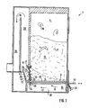
- Fig. 1 eine Schnittansicht einer ersten Ausführungsform der erfindungsgemäßen Heizvorrichtung;
- Fig. 2 eine Schnittansicht einer zweiten Ausführungsform einer Heizvorrichtung nach Fig. l;
- Fig. 3 eine perspektivische Ansicht auf eine Einzelheit in einer Heizvorrichtung nach Fig. 2, auf eine Stützeinrichtung.
- Figure 1 is a sectional view of a first embodiment of the heating device according to the invention.
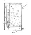
- Fig. 2 is a sectional view of a second embodiment form of a heater according to Fig. l;
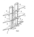
- Fi g. 3 is a perspective view of a detail in a heating device according to FIG. 2, on a support device.
Die Heizvorrichtung 2 kann durchaus auch einen handelsüblichen Unterbrandofen aufweisen, da es möglich ist, die Erfindung auch in Verbindung mit Standardöfen einzusetzen. Ferner ist es im Rahmen der Erfindung auch möglich, übliche Unterbrandöfen mit einer derartigen Vorrichtung nachzurüsten, daß sie der erfindungsgemäßen Heizvorrichtung 2 entsprechen. Der Füllschachtraum 4 ist mit Festbrennstoff 6 gefüllt. Hier kann hochwertiges und vor allem auch niederwertiges Brenngut, beispielsweise Holzspäne, Sägespäne, Holzabfälle, Sägemehl und dgl. verwendet werden. Unterhalb eines Hauptrostet 8 ist eine Zuführkanal 10 für Verbrennungsluft 12 vorgesehen, über welchen ein Glutstock 14 versorgt wird. Ein Abbrand des Brenngutes 16 erfolgt von unten, wobei Abgase 18 über einen Abzugskanal 20, der mit einem Kamin verbunden ist, abgeleitet werden. In einem unteren Bereich des Abzugskanals 20 ist ein Brennschacht 22 vorgesehen, der von einer Brenngut-Stützeinrichtung 24 begrenzt wird. Die Brenngut-Stützeinrichtung verhindert, daß Brenngut 16 in den Brennschacht 22 gelangt, ermöglicht jedoch den Austritt von Rauch-oder Schwelgasen 26, welche sich durch Erwärmung des noch unverbrannten Brenngutes 16 in dem Füllschachtraum 4 entwickeln. Eine Abgas-Austrittsfläche 28 weist eine Vielzahl von Abgas-Austrittsöffnungen 30 auf, durch welche unverbrannte Schwelgase 26 in Einzelgasströmen hindurchtreten können. In einem unteren Bereich des Brennschachtes 22, unmittelbar an die Brenngut-Stützeinrichtung 24 angrenzend ist eine Zutrittsöffnung 32 für Sekundärluft 34 vorgesehen.The
Die Sekundärluft 34 tritt durch eine einstellbare Luftzuführungsöffnung 36 zusammen mit der primären Verbrennungsluft 12 in eine Luftvorlagekammer 38 unterhalb des Hauptrostes 8 ein, wo sie an dem Hauptrost 8 entlangstreichen und sich dabei erwärmen kann: Durch den Kaminzug wird sie an der Brenngut-Stützeinrichtung 24 entlanggeführt und trifft dort auf die Einzelgasströme der Schwelgase 26. Dabei findet eine intensive Verwirbelung der Schwelgase 26 mit der Sekundärluft 34 statt, so daß sich ein zündfähiges Luft/Gas-Gemisch 40 ergibt. Die Anfeuerung der Heizvorrichtung 2 erfolgt durch den Hauptrost 8 hindurch in der Nähe eines Brenngut-Bereiches, in welchem Brenngut 16 sowohl an die Stützeinrichtung 24 als auch an den Hauptrost 8 angrenzt, da hierdurch eine frühzeitige Zündung des Luft/Gas-Gemisches auch in einer frühen Anfeuerungsphase gewährleistet ist. Ein besonderer Sicherheitseffekt ergibt sich aus der Führung der Sekundärluft 34 aus dem Zuführkanal 10, da hierdurch Gase, die möglicherweise auch unter den Hauptrost 8 gelangen, mit der Sekundärluft 34 dem Brennschacht 22 zugeführt werden und nicht in der Luftvorlagekammer 38 eine unerwünschte Flammenbildung bewirken können. Auch wenn das Anzünden der Heizvorrichtung 2 in einem vorderen Bereich des Hauptrostes 8 erfolgt, wird die Glutwanderung des Glutstocks 14 in Richtung auf den rückwärtigen Bereich durch die Strömung der Sekundärluft 34 gefördert.The
Mit einer derartigen Anordnung kann eine Nachverbrennung entstehender Schwelgase 26 erzielt werden, auch ohne daß ein Gebläse für Sekundärluft oder eine Fremdenergiequelle erforderlich wäre. Durch den Verzicht.auf ein Gebläse für die Sekundärluft ergibt sich der Vorteil, daß der natürliche Kaminzug auch auf die Primärluftzuführung wirkt und kein Rückstau der Primärluft stattfinden kann.With such an arrangement, afterburning of the smoldering
Die Zutrittsöffnung 32 erstreckt sich-- wie auch die Stützeinrichtung 24 - über die Innenbreite der Heizvorrichtung 2. Ihre Öffnungsfläche wird durch den Abstand der hinteren Rückwand 42 des Brennschachtes von der Stützeinrichtung 24 festgelegt. In der in Fig. 1 dargestellten Ausführungsform ist die Stützeinrichtung 24 schwenkbeweglich gelagert und ermöglicht so eine Einstellung der Fläche der Zutrittsöffnung 32 mittels eines Einstellgestänges 44, das an einen den Hauptrost 8 durchtretenden Betätigungsarm 46 der Stützeinrichtung 24 angelenkt" ist und von der Beschickungsseite eine Einstellung der Fläche der Zutrittsöffnung 32 ermöglicht. Der Hauptrost 8 weist Längsstäbe 48 auf, wobei der Betätigungsarm 46 den Schlitz zwischen zwei Längsstäben 48 durchtritt und somit in Längsrichtung des Hauptrostes frei beweglich ist.Like the
Der besondere Vorteil dieser Einstellmöglichkeit besteht darin, daß je nach Art und Dichte des Brenngutes 16 ein ideales, d. h., stöchiometrisches Luft/Gas-Gemisch 40 in dem Brennschacht 22 eingestellt werden kann. Ein dichteres Brenngut 16, beispielsweise Sägemehl,erfordert für die Nachverbrennung eine größere Fläche der Zutrittsöffnung 32. Hingegen kann bei großstückiger Verfeuerung von trockenem Holz die Fläche der Zutrittsöffnung 32 klein gewählt werden. Zur Erzielung einer optimalen Nachverbrennung, ist es somit lediglich notwendig, die Stützeinrichtung 24 mittels des Einstellgestänges 44 in eine für die Verbrennung des vorhandenen Brenngutes geeignete Stellung einzustellen.The particular advantage of this setting option is that, depending on the type and density of the firing
In Fig. 2 ist eine weitere Ausführungsform der Erfindung dargestellt, wobei gleiche Bezugszeichen auf gleiche oder entsprechende Teile hinweisen. Hierbei ist die Stützeinrichtung 24 starr; für die Regelung und/oder Steuerung der Fläche der Zutrittsöffnung 32 wird die Rückwand 42 des Brennschachtes 22 verwendet. Da hier geringere Temperaturen vorherrschen, ergibt sich damit der Vorteil, daß auch eine automatische Regelung in Abhängigkeit von dem Verbrennungszustand leichter realisierbar ist, insbesondere auch, da die Rückwand 42 um eine Achse 50 geschwenkt werden kann, ohne daß Brenngut 16 bewegt werden müßte, wie es beim Schwenken der Stützeinrichtung 24 in der ersten Ausführungsform erforderlich ist.2 shows a further embodiment of the invention, the same reference numerals indicating the same or corresponding parts. Here, the
Oberhalb des Brennschachtes 22 ist in der Ausführungsform gemäß Fig. 2 eine Nachverbrennungskammer 52 vorgesehen. Diese Nachverbrennungskammer 52 steht mit dem Brennschacht 22 unmittelbar und mit der durch den Glutstock aufgeheizten Stützeinrichtung 24 mittelbar in Wärmeverbindung. Über Zutrittsöffnungen 54 wird weitere Sekundärluft eingeleitet, wobei auch hier eine Vorwärmung vorteilhaft ist. Dadurch, daß die Zuführungsebene 56 der Zutrittsöffnungen 54 oberhalb des Brennschachtes 22 liegt, erfolgt eine möglichst weitgehende Entkopplung der Verbrennung in dem Brennschacht 22 von der Verbrennung in der Nachverbrennungskammer 52.A
Besonders vorteilhaft ist die Nachbrennkammer 52 in vertikaler Verlängerung des sich durch den Zutritt der Sekundärluft 34 in dem Brennschacht 22 ergebenden Strömungskanales 58 angeordnet. Dadurch fallen in die Nachverbrennungskammer 52 gelangende Aschepartikeln auf den Boden derselben und bei entsprechend schräger Anordnung der Rückwand 42 in die Luftvorlagekammer 38, wo sie mit der Verbrennungsasche zusammen entfernt werden können.The
In dieser Ausführungsform sind oberhalb der Nachverbrennungskammer 52 Prallelemente 60 vorgesehen, die von ihrer Oberseite her abgehängt sind, wobei sie zumindest nicht dauernd die seitlichen Wände der Nachverbrennungskammer 52 berühren. Durch eine derartige wärmegedämmte Aufhängung ergibt sich die Möglichkeit, diese hochwarmfesten Prallelemente 60 bis zur Weißglut aufzuheizen, wodurch hier eine zusätzliche Nachverbrennung stattfinden kann. Die Prallelemente 60 können vorzugsweise aus Metall bestehen, beispielsweise aus einer Flacheisen-Anordnung in einem räumlichen Zickzackmuster, wobei die Hauptrichtung in Strömungsrichtung nach außen weisen sollte, um heiße Gase den Wänden der Nachverbrennungskammer 52 zur Verbesserung des dort stattfindenden Wärmetausches zuzuleiten.In this embodiment, baffle elements 60 are provided above the
In einem oberen Bereich des Füllschachtes 4 sind in dieser Ausführungsform einstellbare Druckausgleichsöffnungen 62 vorgesehen, mit welchen der Druck der Schwelgase 26 im Verhältnis zu dem Druck der Sekundärluft 34 und damit deren Mischverhältnis einstellbar ist. Die Druckausgleichsöffnungen 62 sind in einer Füllöffnung 64 an der Vorderseite'des Füllschachtraumes vorgesehen.In an upper area of the filling
Eine Kurzschlußklappe 66 zwischen dem Füllschachtraum 4 und dem Abzugskanal 20 kann beim Nachfüllen während des Betriebs geöffnet werden, um einen Rückstau der Schwelgase 26 zu verhindern. Mit einem oberhalb des Brennschachtes 22 angeordneten Schauglas 67 kann die Nachverbrennung kontrolliert werden.A short-
In Fig. 3 ist eine Ausführungsform einer Stützeinrichtung in einer Rückansicht schräg von hinten dargestellt. Die Stützeinrichtung ist aus einem hochwarmfesten Material, beispielsweise Gußeisen oder hochwarmfestem Stahl und ist so gelagert, daß die Übergangsstellen einen hohen Wärmewiderstand bilden. Die Stützeinrichtung 24 ist als starrer Rost mit hoher Wärmeleitfähigkeit und geringer Wärmekapazität ausgebildet, wodurch es möglich ist, auch bei einem kleinen Glutstock ein schnelles Aufheizen der Stützeinrichtung 24 zu gewährleisten und diese als Zündeinrichtung für das Luft/Gas-Gemisch 40 zu verwenden. Die Stützeinrichtung 24 weist eine Mehrzahl vorzugsweise vertikaler, zueinander etwa parallel angeordneter Stäbe 68 auf, die sich nach unten verjüngen. An den Stäben 68 sind mit ihrer von dem Glutstock abgewandten Seite Stützschienen 70 befestigt, welche übereinander angeordnet und in Gegenrichtung zum Schüttwinkel des Brenngutes geneigt sind. Die Breite der einzelnen Stützschienen ist so gewählt, daß auch bei dem geringsten auftretenden Schüttwinkel des Brenngutes 16 die Stützeinrichtung 24 das Brenngut 16 abfängt.In Fig. 3 an embodiment of a support device is shown obliquely from behind in a rear view. The support device is made of a heat-resistant material, for example cast iron or heat-resistant steel, and is mounted in such a way that the transition points form a high thermal resistance. The
Gegenüber einer einfachen Siebanordnung ergibt sich der besondere Vorteil, daß eine relativ große freie Fläche für den Durchtritt von Abgasen 18 ermöglicht werden kann, die im Beispielsfalle dem gasundurchlässigen Flächenteil der Stützeinrichtung 24 entspricht, sowie, daß Schwelgase 26, die die Stützeinrichtung 24 durchtreten, umgelenkt werden und somit bereits beim Durchtreten der Stützeinrichtung 24 Turbulenzen erzeugt werden, die die spätere Verwirbelung mit der Sekundärluft 34 begünstigen.Compared to a simple sieve arrangement, there is the particular advantage that a relatively large free area can be made possible for the passage of
Dadurch, daß der Strömungswiderstand in einem unteren Bereich der Stützeinrichtung 24 geringer als in einem oberen Bereich ist, ergibt sich eine Begünstigung des unteren Bereiches durch die spezielle Ausbildung der Stützeinrichtung 24, mit welcher eine ungleichmäßige Verteilung der Schwelgasströmung durch die Abgas-Austrittsfläche 28 verhindert wird. Auch in einer Anfeuerungsphase mit einem kleinen Glutstock wird dadurch ein hinreichend großer Anteil von Schwelgasen 26 durch den Glutstock 14 hindurch geleitet und kann dort für die Verbrennung aufgespalten werden.Because the flow resistance in a lower area of the
Eine besonders intensive Verwirbelung der Schwelgase 26 mit der Sekundärluft 34 zu einer stöchiometrischen Luft/ Gas-Gemisch 40 ergibt sich dadurch, daß - wie in Fig. 3 dargestellt - die Sekundärluft 34 in den freien Strömbereichen hinter den Stäben 68 aufsteigen kann, wobei in jedem durch eine Stützschiene 70 gebildeten Teilbereich an den Rändern dieses Strömkanales eine zusätzliche Turbulenz erzeugt wird, die je einen Teil des nach oben gerichteten Stromes der Sekundärluft 34 erfaßt, abzweigt und einer lokalen Verwirbelungszone mit zwei schräg zueinander gerichteten Gasströmen zuführt.A particularly intensive swirling of the
Um zu erreichen, daß kein Brenngut 16 in den Brennschacht 22 bzw. den Strömungskanal 58 gelangen kann, sollte der geringste auftretende Schüttwinkel des Brenngutes größer sein als ein Winkel, der sich durch den Winkel zwischen der Waagerechten und der gedachten Verbindungslinie zwischen der Vorderkante einer oberen Stützschiene 70 und dem Durchtrittsbereich der Stäbe 68 durch die darunter gelegene Stützschiene 70 ergibt. Insofern hat der gegen die Waagerechte gemessene geringste auftretende Schüttwinkel des verwendeten Brenngutes 16 Einfluß auf die konstruktive Ausbildung der Stützeinrichtung 24. In einer besonders bevorzugten Ausführungsform entspricht der Winkel zwischen den als Abfangflächen verwendeten Stützschienen 70 und den Stäben 68 etwa dem Schüttwinkel des verwendeten Brenngutes. Dadurch, daß die Abgas-Austrittsöffnungen 30 groß gewählt werden können, wird eine Behinderung der aus dem unverbrannten Brenngut 16 austretenden Schwelgase 26 vermieden. Dadurch wird eine intensive und großflächige Verwirbelung der Schwelgase 26 mit der Sekundärluft 34 ermöglicht, die zu einer gleichmäßigen und guten Nachverbrennung führt.In order to ensure that no firing
Claims (14)
Applications Claiming Priority (2)
| Application Number | Priority Date | Filing Date | Title |
|---|---|---|---|
| DE3218334A DE3218334C2 (en) | 1982-05-14 | 1982-05-14 | Heater |
| DE3218334 | 1982-05-14 |
Publications (2)
| Publication Number | Publication Date |
|---|---|
| EP0105081A2 true EP0105081A2 (en) | 1984-04-11 |
| EP0105081A3 EP0105081A3 (en) | 1984-07-25 |
Family
ID=6163691
Family Applications (1)
| Application Number | Title | Priority Date | Filing Date |
|---|---|---|---|
| EP83104588A Withdrawn EP0105081A3 (en) | 1982-05-14 | 1983-05-10 | Heating device |
Country Status (2)
| Country | Link |
|---|---|
| EP (1) | EP0105081A3 (en) |
| DE (1) | DE3218334C2 (en) |
Cited By (5)
| Publication number | Priority date | Publication date | Assignee | Title |
|---|---|---|---|---|
| FR2603686A1 (en) * | 1986-09-05 | 1988-03-11 | Olmotti Humbert Marin | Universal heating apparatus |
| WO1992019916A1 (en) * | 1991-05-02 | 1992-11-12 | Concept Gesellschaft Für Kreative Produktentwicklung Gesellschaft M.B.H. | Furnace for burning pieces of timber |
| AT398618B (en) * | 1989-02-08 | 1995-01-25 | Traxler Rudolf | FIRE FOR THE COMBUSTION OF SOLID FUELS |
| WO1997024556A1 (en) * | 1996-01-01 | 1997-07-10 | Karl Ackermann | Combustion furnace with a secondary-air feed, in particular an under-burning boiler |
| WO2014170814A1 (en) * | 2013-04-15 | 2014-10-23 | Berlincioni Giovanni | A pellet oven |
Families Citing this family (5)
| Publication number | Priority date | Publication date | Assignee | Title |
|---|---|---|---|---|
| GB2139752A (en) * | 1983-05-11 | 1984-11-14 | Vermont Castings | Heating apparatus |
| DE3606125A1 (en) * | 1986-02-26 | 1987-08-27 | Buderus Ag | Heating apparatus for solid fuels |
| CH678652A5 (en) * | 1989-04-28 | 1991-10-15 | Heitzmann Ag | |
| AT406515B (en) * | 1996-03-11 | 2000-06-26 | Friedrich Ehgartner | FIREPLACE |
| CN105066182A (en) * | 2015-07-20 | 2015-11-18 | 广西田东兴鑫窑炉工程有限责任公司 | Intelligent energy-saving environment-friendly stove |
Citations (11)
| Publication number | Priority date | Publication date | Assignee | Title |
|---|---|---|---|---|
| FR374445A (en) * | 1907-01-15 | 1907-06-12 | Emile Bodson | Grate bars for furnaces of boilers and others |
| US1407516A (en) * | 1919-11-24 | 1922-02-21 | Budd Lester | Adjustable air-shutter construction for furnaces |
| FR598915A (en) * | 1925-05-29 | 1925-12-29 | Genevet Et Cie | Improvements made to grill bars for fireplaces |
| FR644118A (en) * | 1926-11-20 | 1928-10-02 | Steam boiler hearth grate | |
| US1732442A (en) * | 1928-02-29 | 1929-10-22 | Jaeger Ralph | Positive-feed pressure eliminator for sawdust burners |
| DE497921C (en) * | 1928-04-20 | 1930-05-15 | Gustav Korngiebel | Secondary draft regulator |
| CH193570A (en) * | 1937-02-16 | 1937-10-31 | Von Roll Ag | Firing device for gas-rich solid fuels in central heating boilers, stoves and stoves. |
| FR965285A (en) * | 1950-09-07 | |||
| FR1224838A (en) * | 1958-12-23 | 1960-06-27 | Licentia Ekman & Brundin | Process for obtaining complete and smokeless combustion of solid fuels, and stove for carrying out the process |
| DE2934721A1 (en) * | 1979-08-28 | 1981-03-12 | geb. Stiasny Anneliese 8261 Marktl Harlander | Solid, liquid or gas fired water boiler - has fuel grate and adjacent refractory insert with secondary air supply below combustion chamber |
| FR2499222A1 (en) * | 1981-02-04 | 1982-08-06 | Carbofuel Officine Meccaniche | HOT WATER OR STEAM GENERATOR WORKING ON SOLID FUELS, WITH HIGH VOLATILE CONTENT |
Family Cites Families (2)
| Publication number | Priority date | Publication date | Assignee | Title |
|---|---|---|---|---|
| FR961506A (en) * | 1950-05-13 | |||
| DE2927152A1 (en) * | 1979-07-05 | 1981-01-15 | Hdg Kessel & App | Solid and liquid fuel fired furnace - has body with afterburner chamber between loading shaft and combustion chamber |
-
1982
- 1982-05-14 DE DE3218334A patent/DE3218334C2/en not_active Expired
-
1983
- 1983-05-10 EP EP83104588A patent/EP0105081A3/en not_active Withdrawn
Patent Citations (11)
| Publication number | Priority date | Publication date | Assignee | Title |
|---|---|---|---|---|
| FR965285A (en) * | 1950-09-07 | |||
| FR374445A (en) * | 1907-01-15 | 1907-06-12 | Emile Bodson | Grate bars for furnaces of boilers and others |
| US1407516A (en) * | 1919-11-24 | 1922-02-21 | Budd Lester | Adjustable air-shutter construction for furnaces |
| FR598915A (en) * | 1925-05-29 | 1925-12-29 | Genevet Et Cie | Improvements made to grill bars for fireplaces |
| FR644118A (en) * | 1926-11-20 | 1928-10-02 | Steam boiler hearth grate | |
| US1732442A (en) * | 1928-02-29 | 1929-10-22 | Jaeger Ralph | Positive-feed pressure eliminator for sawdust burners |
| DE497921C (en) * | 1928-04-20 | 1930-05-15 | Gustav Korngiebel | Secondary draft regulator |
| CH193570A (en) * | 1937-02-16 | 1937-10-31 | Von Roll Ag | Firing device for gas-rich solid fuels in central heating boilers, stoves and stoves. |
| FR1224838A (en) * | 1958-12-23 | 1960-06-27 | Licentia Ekman & Brundin | Process for obtaining complete and smokeless combustion of solid fuels, and stove for carrying out the process |
| DE2934721A1 (en) * | 1979-08-28 | 1981-03-12 | geb. Stiasny Anneliese 8261 Marktl Harlander | Solid, liquid or gas fired water boiler - has fuel grate and adjacent refractory insert with secondary air supply below combustion chamber |
| FR2499222A1 (en) * | 1981-02-04 | 1982-08-06 | Carbofuel Officine Meccaniche | HOT WATER OR STEAM GENERATOR WORKING ON SOLID FUELS, WITH HIGH VOLATILE CONTENT |
Cited By (5)
| Publication number | Priority date | Publication date | Assignee | Title |
|---|---|---|---|---|
| FR2603686A1 (en) * | 1986-09-05 | 1988-03-11 | Olmotti Humbert Marin | Universal heating apparatus |
| AT398618B (en) * | 1989-02-08 | 1995-01-25 | Traxler Rudolf | FIRE FOR THE COMBUSTION OF SOLID FUELS |
| WO1992019916A1 (en) * | 1991-05-02 | 1992-11-12 | Concept Gesellschaft Für Kreative Produktentwicklung Gesellschaft M.B.H. | Furnace for burning pieces of timber |
| WO1997024556A1 (en) * | 1996-01-01 | 1997-07-10 | Karl Ackermann | Combustion furnace with a secondary-air feed, in particular an under-burning boiler |
| WO2014170814A1 (en) * | 2013-04-15 | 2014-10-23 | Berlincioni Giovanni | A pellet oven |
Also Published As
| Publication number | Publication date |
|---|---|
| DE3218334C2 (en) | 1984-02-16 |
| DE3218334A1 (en) | 1983-11-17 |
| EP0105081A3 (en) | 1984-07-25 |
Similar Documents
| Publication | Publication Date | Title |
|---|---|---|
| DE3218334C2 (en) | Heater | |
| DE4402172C2 (en) | Process for combusting fuel and plant for carrying out the process | |
| DE3705153C2 (en) | ||
| AT409892B (en) | HEATING DEVICE FOR SOLID FUELS, IN PARTICULAR COMPACT OVENS OR FIREPLACE | |
| EP0589026B1 (en) | Process and device for regulating the burning of solid fuels in a combustion plant | |
| DE4204163C2 (en) | Solid fuel burning furnace, in particular fireplace | |
| DE4012363C2 (en) | Solid fuel burning device, especially wood | |
| DE3927803C2 (en) | Solid fuel heater, especially tiled stove use | |
| DE2812962C2 (en) | Wood stove | |
| DE8214176U1 (en) | HEATING DEVICE | |
| AT397551B (en) | INCINERATOR | |
| DE1451505A1 (en) | Process for incinerating household waste and / or industrial waste as well as mechanical grate firing to carry out this process | |
| DE69923418T2 (en) | Method for controlling the combustion air and corresponding control arrangement | |
| DE4009316C2 (en) | Solid fuel heater | |
| DE3345963C2 (en) | Solid fuel fireplace | |
| DE3902091A1 (en) | Tiled stove heating insert | |
| DE19729506C2 (en) | Boiler for firing solid fuels | |
| DE19537843A1 (en) | Stove supply air distributor | |
| AT398618B (en) | FIRE FOR THE COMBUSTION OF SOLID FUELS | |
| DE3801407C2 (en) | ||
| EP1326053B1 (en) | Combustion air preheater in firebox | |
| DE102020110114A1 (en) | Small combustion system and method for operating a small combustion system | |
| DE605401C (en) | Filling shaft furnace with half gas firing | |
| DE4101101C2 (en) | Solid fuel heater with auxiliary air supply | |
| CH680608A5 (en) |
Legal Events
| Date | Code | Title | Description |
|---|---|---|---|
| PUAI | Public reference made under article 153(3) epc to a published international application that has entered the european phase |
Free format text: ORIGINAL CODE: 0009012 |
|
| AK | Designated contracting states |
Designated state(s): AT CH FR GB IT LI SE |
|
| PUAL | Search report despatched |
Free format text: ORIGINAL CODE: 0009013 |
|
| AK | Designated contracting states |
Designated state(s): AT CH FR GB IT LI SE |
|
| 17P | Request for examination filed |
Effective date: 19850110 |
|
| 17Q | First examination report despatched |
Effective date: 19860228 |
|
| STAA | Information on the status of an ep patent application or granted ep patent |
Free format text: STATUS: THE APPLICATION IS DEEMED TO BE WITHDRAWN |
|
| 18D | Application deemed to be withdrawn |
Effective date: 19861231 |