EP0105032A2 - Procédé et appareil pour irradier des objets avec des rayons X - Google Patents
Procédé et appareil pour irradier des objets avec des rayons X Download PDFInfo
- Publication number
- EP0105032A2 EP0105032A2 EP83810402A EP83810402A EP0105032A2 EP 0105032 A2 EP0105032 A2 EP 0105032A2 EP 83810402 A EP83810402 A EP 83810402A EP 83810402 A EP83810402 A EP 83810402A EP 0105032 A2 EP0105032 A2 EP 0105032A2
- Authority
- EP
- European Patent Office
- Prior art keywords
- rays
- electrons
- incoming
- photons
- ray
- Prior art date
- Legal status (The legal status is an assumption and is not a legal conclusion. Google has not performed a legal analysis and makes no representation as to the accuracy of the status listed.)
- Granted
Links
Images


Classifications
-
- G—PHYSICS
- G21—NUCLEAR PHYSICS; NUCLEAR ENGINEERING
- G21K—TECHNIQUES FOR HANDLING PARTICLES OR IONISING RADIATION NOT OTHERWISE PROVIDED FOR; IRRADIATION DEVICES; GAMMA RAY OR X-RAY MICROSCOPES
- G21K1/00—Arrangements for handling particles or ionising radiation, e.g. focusing or moderating
-
- H—ELECTRICITY
- H05—ELECTRIC TECHNIQUES NOT OTHERWISE PROVIDED FOR
- H05G—X-RAY TECHNIQUE
- H05G2/00—Apparatus or processes specially adapted for producing X-rays, not involving X-ray tubes, e.g. involving generation of a plasma
-
- A—HUMAN NECESSITIES
- A61—MEDICAL OR VETERINARY SCIENCE; HYGIENE
- A61N—ELECTROTHERAPY; MAGNETOTHERAPY; RADIATION THERAPY; ULTRASOUND THERAPY
- A61N5/00—Radiation therapy
- A61N5/10—X-ray therapy; Gamma-ray therapy; Particle-irradiation therapy
- A61N2005/1085—X-ray therapy; Gamma-ray therapy; Particle-irradiation therapy characterised by the type of particles applied to the patient
- A61N2005/1091—Kilovoltage or orthovoltage range photons
Definitions
- the present invention generally relates to the production of X-rays and, more particularly, to a method of and arrangement for producing X-rays by the Compton scattering effect in a desired frequency range suitable for medical diagnostic and therapeutic, or industrial testing, purposes. Still more particularly, this invention relates to a novel method of and apparatus for electronically steering an X-ray beam, as well as to a method of and apparatus for X-raying an object with a narrow band frequency characteristic.
- X-rays are generated for medical diagnostic purposes by using a cathode tube, wherein a stream of electrons is directed towards a metal plate for impingement thereon, to thereby cause the metal material to emit radiation in the X-ray range which, for diagnostic purposes, lies in the range from about 20Kev to 100Kev. Since this process depends on the excitation of the shell electrons of the metal and on spontaneous level change within the atom shell envelope, accompanied by sudden energy release in the form of X-rays, the characteristics of individual X-ray photons cannot be determined.
- the conventonal X-ray tube emits a highly divergent X-ray beam with a distribution of the frequencies or energy levels of the photons in the X-ray beam over a very wide range.
- Mechanical shutters are used to control the emission angle.
- the exposure of the object to X-rays or, in other words, the dosage of the X-ray radiation is -far in excess of the necessary level since, in order to achieve the desired dosage of the beneficial X-ray energy level, the object is simultaneously exposed to a substantial dosage of X-ray radiation outside the beneficial range.
- X-rays in the range from about 1OKev to about 250Kev are used and, conventionally, for the higher energy range, a linear accelerator may be used to accelerate a stream of electrons against a metal plate to cause X-ray emission.
- a linear accelerator may be used to accelerate a stream of electrons against a metal plate to cause X-ray emission.
- the very same drawbacks described above are stil present, because the issuing high energy X-rays also have a wide angle beam and a broad band frequency characteristic.
- polarized X-rays are desired.
- polarized X-rays are produced by passing unpolarized X-rays through materials, such as graphite.
- materials such as graphite.
- this is a very inefficient process.
- polarized X-rays have never, to our knowledge,'been used and, hence, their potential utility remains to be explored.
- Still another drawback of conventional X-ray apparatus is that the X-ray beam itself has never been electronically steered. It is well known that X-ray scanning of a patient is a highly desirable medical technique and, hence, the conventional techniques to accomplish scanning are to mechanically move the patient, or to mechanically move the X-ray tube itself, or to mechanically move the exit shutter of the X-ray apparatus. In some hospitals, there are huge X-ray machines which place the patient on a table, and move the patient in a desired direction. Also, the patient can remain stationary, and the X-ray machine can move around the patient. All of these prior art techniques are very cumbersome and unwieldy and, most importantly, are slow, i.e. on the order of 15-20 seconds or more and, hence, patient movement can cause X-ray blur.
- the Compton effect is characterized as follows: An incoming photon supplied by a light source, such as a laser, is collided with an incoming electron supplied by an electron accelerator. The result of the collision is that the electron loses energy, and the photon gains energy. The outgoing or deflected photons have a very high energy level, and typically are in the gamma-ray range identified above.
- the Compton effect to the best of our knowledge, has never been used to generate X -rays for bio-medical and industrial investigations.
- Another object of this invention is to produce X-rays in a desired range suitable for medical diagnostic, or medical therapeutic, or industrial testing purposes.
- An additional object of this invention is to reliably and controllably produce X-rays in a novel manner.
- Another object of this invention is to generate X-rays whose individual photon characteristics can be determined with high accuracy.
- a further object of this invention is to protect medical or industrial operating personnel of X-ray apparatus from undue exposure to X-rays without requiring massive and extensive shielding.
- Still another object of this invention is to expose a patient to be X-rayed to the most beneficial range of X-ray radiation without unduly exposing the patient to radiation outside the beneficial range.
- Still a further object of this invention is to reliably and controllably select the X-ray frequency band to irradiate an article or person to be X-rayed.
- Yet another object of this invention is to efficiently generate polarized X-rays for elemental analysis, as well as for medical applications.
- Yet an additional object of this invention is to provide essentially electronic means for steering an X-ray beam to achieve scanning, rather than by mechanically moving the X-ray apparatus and/or the patient.
- Another object of this invention is to utilize the Compton backscattering effect for bio-medical and industrial applications.
- Another object of this invention is to incorporate a single apparatus for use as a low radiation dosage diagnostic device and for purposes of planning a course of treatment, as well as a high radiation dosage therapy device. This can be achieved either by use of tuned X-ray frequencies in photon activation therapy, or by use of the electron beam itself.
- a further object of this invention is to precisely locate where in a sample a scattering process occurred.
- one feature of the invention resides, briefly stated, in a method of, and apparatus for, producing X-rays in a desired range suitable for medical diagnostic and therapeutic, or industrial testing, purposes. As described below, this desired range lies from about 0.5Kev to about 250Kev.
- a multitude of incoming electrons at a predetermined energy level is passed in one direction along a predetermined path through an interaction region; and a multitude of incoming photons at a predetermined energy level is directed along a direction substantially opposite to the one direction through the interaction region and into colliding relationship with the incoming electrons.
- the resulting interaction between the incoming electrons and the incoming photons causes, inter alia, outgoing photons at an increased energy level to be propagated substantially along the one direction towards an object to be X-rayed.
- the object can be animate or inanimate.
- the increased energy level of the photons lies within the above-described desired range characteristic of X-rays.
- the energy level of the incoming electrons is carefully controlled to propagate the outgoing photons as X-rays.
- the novelty of this invention resides in the recognition, for the first time, that photons of much lower energy than those ordinarily produced in nuclear physics research can be generated using the Compton backscattering effect by carefully controlling the energy level of the incoming electrons.
- the resulting X-rays can be used for many applications including, but not limited to, medical diagnosis, radiation therapy, elemental analysis, industrial radiography.
- Another feature resides in the fact that the X-rays produced by this invention are emitted as a very narrow angle beam.
- the highly directional nature of the X-rays tends to reduce, although not entirely eliminate, the need for mechanical shutters, shielding, etc. It also is highly desirable when combined wih the scnning feature described in detail below.
- the X-rays produced by this invention are emitted in a very narrow frequency band.
- the object is typically exposed to too large a dose of X-rays.
- only a narrow range of the X-ray spectrum is typically required for any particular irradiation.
- a patient need only be irradiated with that particular beneficial range.
- the fact that the conventional X-rays also contain frequencies outside of the beneficial range is very undesirable, and represents a potential source of overdosage and side effect problems.
- the narrow band frequency characteristic of the X-rays produced by this invention overcomes all of these disadvantages.
- tunability aspect whereby the particular narrow band frequency in the X-ray spectrum can be selected by the operator.
- a physician for example, can select the X-ray frequency most beneficial for a particular procedure. In the prior art, no such tuning control exists.
- the scanning of X-ray beams in the above-identified desired:.range has been implemented by slow mechanical arrangements, but not by electronically deflecting the X-ray beam.
- This invention has realized a significant breakthrough in the X-ray scanning field. It will be appreciated that X-ray beams in the desired range unlike electrons, consist of uncharged particles which cannot be electronically, magnetically or optically deflected.
- This invention proposes to electronically steer the X-ray beam by varying the position in space of the interaction region.
- the incoming photons of very low energy are optically deflected by an electronically controlled optical scanner, and the incoming electrons are magnetically deflected by a magnetic arrangement.
- the deflections of the photons and electrons must be carefully controlled so that they are always directed along coincident paths.
- the X-ray beam has been displaced not by deflecting the X-ray beam itself, but by moving the interaction region.
- Still another feature resides in the fact that the Compton-generated X-rays are polarized.
- polarized X-rays have never been used and, hence, their potential utility remains to be explored.
- this invention increases the sensitivity of the method and avoids the conventional inefficient graphite-mediated process described above.
- Fig. 1 A multitude of incoming electrons schematically represented by the incoming electron e l is directed in one direction to an interaction region.
- a multitude of incoming photons schematically represented by the incoming photon P1 is directed in the opposite direction to the interaction region. If the incoming photon having a quantum energy level E1 collides with the incoming electron having a kinetic energy level E, then the incoming photon gains energy and increases to a quantum energy level E 2 at the expense of the incoming electron which loses energy during the collision interaction.
- the outgoing photons are propagated substantially backwardly in the opposite direction to that of the incoming photons.
- the outgoing photons are deflected within a scattering angle 0 to form a cone-shaped beam.
- the scattering angle is grossly exaggerated in Fig. 1; in reality, this angle is very close to zero degrees such that the outgoing photon trajectory is almost co-linear with the incoming photon trajectory.
- X-rays may be defined as photons falling in the range from about 0.5Kev to about 250Kev. More particularly, the range from about 20 Kev to about 100Kev, and particularly the lower end of the range, is best for medical diagnosis, with 40Kev being typical for such standard applications as chest X-ray examinations.
- the low energy range of 10kev to about 30Kev is best suited for X-ray radiation therapy of superficial tumors or for photon activation therapy, whereas the higher energy range from 30Kev to 250Kev is used for treatment of deeper tumors.
- the range from about 0.5Kev to about 100Kev is best.
- an apparatus for producing X-rays in the above-identified desired range suitable for medical diagnostic and therapeutic, or industrial testing, purposes in accordance with the method of this invention comprises a laser source 1 operative for emitting photons, either in a continuous or pulsed manner, in an optical cavity bounded by a rear reflecting concave mirror 2 and a front reflecting concave mirror 3.
- The-mirrors 2, 3 reflect low energy photons, that is photons having an energy level below that of X-rays. As described below, the mirrors are transmissive to X-rays.
- the low energy photons are reflected back" and forth between the mirrors 2, 3.
- the photons reflected off the front mirror 3 and directed from right to left across the designated interaction region correspond to the incoming photons shown in Fig. 1.
- any electron accelerator but particularly one that can supply high current, good stability, and good beam quality such as a compact storage ring 4 can be used to accelerate the electrons around a so-called racetrack that is composed of straight and circular sections.
- a pair of arcuate bend electromagnets Ml and M2 are situated at the spaced-apart circular sectons of the racetrack, and are operative to magnetically act on the electrons to cause them to repeatedly circulate at a predetermined energy level E along the closed loop.
- the electromagnets have windings which are electrically connected in series and to a voltage supply V and a variable control resistor R.
- electrons can be introduced into the storage ring by many different types of injectors.
- the injector illustrated is a microtron I which is operative to move the electrons at initial low kinetic energy levels along a trajectory consisting of circles having increasing diameters and being tangent to each other at a common point. This electron trajectory spirals outwardly to eventually intersect with a straight section of the racetrack, whereupon the now higher kinetic energy electrons are caused to circulate around the racetrack in a narrow beam for very long time periods on the order of hours.
- a high beam current is obtained by repeated injection and stacking of a plurality of pulses of electrons. Once the desired beam current is obtained, the .
- a radio frequency cavity 5 is also positioned in a straight section of the racetrack to restore lost energy to the circulating electrons during each revolution, because there are unavoidable attenuation losses.
- Position detectors may be used to monitor the position of the electrons along the racetrack.
- the electrons directed from left to right in Fig. 2 across the interaction region correspond to the incoming electrons of Fig. 1.
- the interaction region is situated in a straight section of the racetrack.
- the incoming electrons and photons are directed in.opposite directions towards each other to cause the Compton collision.
- the outgoing electrons lose energy, but at the energy levels under consideration the electrons lose so little energy during Compton collision that such electrons continue traveling around the storage ring in the same narrow electron beam that such electrons traveled in prior to collision.
- the outgoing photons gain energy, and are propagated towards the right within a cone-shaped beam having a small divergence angle, typically less than 0.01 radians.
- the cone-shaped beam axis is coincident to the incoming photons in the interaction region.
- the outgoing photons of increased energy, i.e. X-rays pass right through the front mirror 3 and impinge on a target 6. Any object, animate or inanimate, may be placed in front of the target 6.
- the object may be any article to be tested, examined or analyzed, or a portion of a body of a patient to be examined or subjected to radiation therapy.
- the target 6 may be X-ray film, or position sensing devices sensitive to X-rays, just to mention a few possibilities.
- the energy E 2 of the scattered or outgoing photon is related to the energy E 1 of the incoming photon by the following equation:
- the energy of the outgoing photons can be varied as a function of the electron energy.
- the electron energy for example by adjusting the continuously variable resistor R
- the kinetic energy of the electrons can be changed, and concomitantly, the energy of the outgoing photons can be adjusted to the desired X-ray range.
- the resistance of the resistor R By changing the resistance of the resistor R, the current to the electromagnetic windings is varied and, in turn, the magnetic field acting on the electrons is changed and, in turn, the radio frequency cavity cooperates with the changed magnetic field to change the kinetic energy of the electrons.
- the typical laser used is an argon laser which emits visible light at about 3 watts of continuous power. This power level is too low for medical diagnostic or radiation therapy techniques. Of course, for nuclear physics research, higher powers are not required.
- huge, massive, large-sized storage rings operate with incoming electron energies in the range from about 300Mev to about 8 Gev.
- the conventional storage ring can have a perimeter on the order of 50 meters, and can have from 8 to 48 electromagnets arranged around the racetrack.
- the gamma rays produced can be anywhere in the multi-Mev to Gev region.
- the laser used in the present invention is preferably a CO 2 laser or a Nd Yag laser which emit infrared light at much higher levels of power.
- a C0 2 laser can emit infrared light at about 10 kilowatts of average power; the Nd Yag laser can emit infrared light at about 1 kilowatt of average power.
- only two bend electromagnets M1 and M2 are used. Rather than a 50 meter perimeter for the racetrack, this invention uses a compact storage ring of about 10 meters in perimeter. Rather than accelerating the electrons to energy levels on the order of billions of electron volts, the electrons are accelerated to much lower levels. For example, as shown in Table I, to produce X-rays at the 40Kev level, the electron energy levels required are in the 32Mev to 142Mev range for the various lasers listed.
- the laser can be operated in a continuous or pulsed mode.
- the pulsed mode is preferred, because it increases the effective power of the laser.
- the electrons are confined in one or more bunches.
- the effective power can be ⁇ improved greatly when the same laser pulse is used over and over by making it repeatedly oscillate between the pair of mirrors 2,3 of the optical cavity. This decreases the repetition rate out of the laser itself.
- the laser is designed to produce pulses which are twice the length of the interaction region.
- the length of the optical cavity is equal to one-half the perimeter of the storage ring, in the case where the storage ring operates with only a single electron bunch.
- a laser pulse interacts several times with the electron bunch, and is only attenuated in the reflections on the mirrors.
- the attenuation per pass can be made very small, on the order of a fraction of 1%, so that a large number of passes through the interaction region may be obtained before a new laser pulse is required.
- the attenuation of the electron bunches due to Compton collisions is also very small, such that the electron beam lifetime is very long, and may be on the order of hours.
- Fig. 3 a simplified perspective view of the compact X-ray apparatus of Fig. 2 is shown, with various components removed for the sake of clarifying the drawing, and with various other components added to show still other features of the invention.
- the laser source ⁇ is situated in a tubular extension 7 which is supported at one side of a vacuum enclosure or main housing 8.
- the rear mirror 2 is situated at the far end of tube 7, and an optical scanner 9, as described below, is situated at the other end of the tube.
- a vacuum ion pump system 10 including a connecting conduit 11 communicates with the interior of the main housing 8, and is operative to evacuate the interior thereof to a high vacuum condition, typically on the order of better than 10 -9 torr for long electron beam-life.
- the storage ring 4, radio frequency cavity 5, the injector I and the pair of curved bend electromagnets M1 and M 2 are all operative as described previously in connection with Fig. 2.
- a pair of deflecting magnet devices 12,13 are located at opposite ends of the interaction region, and their operation in cooperation with the optical scanner 9, is described below in connection with Fig. 4.
- the front reflecting mirror 3 may be mounted within the main housing, or in another extension tube 14 located at the other side of the main housing 8.
- a sample to be X-rayed may be located directly in front of the target 6.
- the sample may represent a patient, and the target may be analog X-ray film or digital X-ray sensitive detectors.
- the injector need not be operative after the current has reached its desired level.
- the injector need not be shut down thereafter, because it can still serve as an independent source of electrons for irradiation applications.
- a non-illustrated extracting magnet assembly at the outlet port of the injector can be energized to deflect the electrons out of their usual insertion path into the closed loop outwardly through the discharge port 22.
- a control unit 15 having a plurality of control modules is electrically connected by wiring (not illustrated for the sake of clarity) to the various components of the X-ray apparatus.
- module 16 supplies power to the injector;
- module 17 supplies power to the bend magnets M1 and M2;
- module 18 supplies power to the radio frequency cavity 5;
- module 19 supplies power to the laser;
- module 20 supplies power to the ion pump 10;
- module 21 supplies power to the optical scanner 9 and the deflecting magnets 12, 13.
- the control unit 15 is mounted on a wheel-mounted frame for ease of movement.
- the X-ray apparatus shown in Fig. 3, except for the control unit, is a relatively compact arrangement and occupies a space about 100 to 200 cubic feet in volume. The small size of the arrangement allows it to be conveniently used in a hospital or industrial setting.
- Fig. 4 this is an enlarged view of the interaction region and those components of the apparatus which vary the direction of propagation of the X-rays to scan the object.
- an X-ray beam consists of uncharged particles which cannot be electronically or magnetically defected
- this invention represents the first time that an X-ray beam has ever been electronically steered.
- X-ray beams have been used in various mechanical scanning arrangements, but they are all too slow, are cumbersome, are unwieldy and are susceptible to blur due to patient movement.
- the components of F ig. 4 provide a very fast electronic scanning which avoids all these drawbacks.
- the X-ray scanning is performed by changing the spatial position of the interaction region. As the interaction region is moved, so the direction of propagation of the X-rays is changed.
- the X-ray beam itself is not deflected, but the photon beam and the electron beam are deflected.
- deflecting magnets 12, 13 are positioned adjacent the electron path at the opposite ends of the interaction region, and are operative, when energized by control module 21, to deflect the electrons out of their normal path in the original interaction region to an offset path.
- the deflector 13 deflects the electrons to a greater extent than the deflector 12 so as to define an inclined offset path, rather than the more horizontal original path. It will be recalled that electrons are charged particles which can be magnetically deflected.
- the photons are optically deflected by the optical scanner 9 such that the incoming photons will collide with the electrons in their new offset inclined path.
- the X -rays are generated at the new offset interaction region.
- the optical scanner 9 and the deflectors 12, 13 must be carefully controlled electronically such that the photon path is coincident with the electron path for each offset path position.
- the original and offset interaction regions represent the end-limiting positions of a scan. It will be appreciated that there are a plurality of intermediate interaction regions between the illustrated end-limiting positions.
- the electronic steering permits the operator to precisely steer the X-ray beam at exactly the area of interest and at high scanning rates. X-ray blur would be reduced not only by the fast scanning speeds, but also by new digital detector techniques, as described below.
- the narrow angle beam width cooperates with the scanning feature to give very accurate and precise positioning control for improved diagnosis and radiation therapy where fine control is critical for patient safety.
- the Compton-generated X -rays are emitted as a very narrow angle conical beam whose scattering angle 9 typically does not exceed 0.01 radians.
- the number n of outgoing photons produced per unit time in a conical solid angle beam is proportional to the number N L of incoming photons that interact with the electrons, to the number N E of electrons, to the frequency f of encounters, and to the cross-section ⁇ of the scattering process, and is inversely proportional to the common geometrical cross-section ⁇ of the electron and photon beams.
- the number of photons produced per unit time is defined as:
- the highly directional nature of the X-rays generated herein tends to reduce, but not entirely eliminate, the need for shielding. Also, it is of great importance in steering the beam during the scanning mode, because the position of a highly directional beam is known with certainty, as opposed to the broad beam patterns of conventional X-ray equipment.
- the target 6 is a detector array composed of a matrix of X-ray sensitive detectors operative for generating an electrical counting signal proportional to the flux, or number of photons per unit time, impinging on each detector.
- the optical scanner 9 and magnetic deflectors 12, 13 used to steer the X-ray beam generate an electrical steering signal indicative of the position of the X-ray beam.
- the counting signal and the steering signal are then conducted to a data acquisition computer 23 which processes these signals and converts them to data indicative of where a scattering interaction may have occurred ion the sample under investigation.
- the data can be displayed on any convenient display such as printer 24.
- Another Compton interaction may occur in the sample, whereby the X-ray photons may collide with electrons in the sample and undergo a Compton reaction.
- the location of the scattering interaction in the sample could not be determined with precision heretofore, because the energy of the individual photons in the scanning beam could not be ascertained.
- the present invention can determine the energy of the individual photons and, hence, greatly advances the field of three-dimensional radiography.
- the detector array may constitute a substantially planar main detector or plate 6 located rearwardly of the object to thereby perform two-dimensional radiography or, in another embodiment, a plurality of substantially planar auxiliary detectors, e.g. detector 6a, can be located at various locations around the object to thereby perform three-dimensional radiography.
- a pair of auxiliary detectors 6a can be arranged at opposite sides of a patient, and the main detector 6 can be arranged behind the patient.
- a curved detector which extends circumferentially around the patient, either completely or partially about the patient, can be used instead of a plurality of planar detectors.
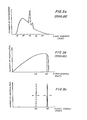
- the emitted X-rays of a conventional X-ray tube have a broad band frequency characteristic.
- the conventional tube output is a continuum of frequencies plus so-called characteristic lines at particular frequencies or energy levels.
- FIG. 5b illustrates the output of a conventional synchrotron.
- the patient will not only be exposed to the beneficial range of frequencies in the vicinity of 40Kev, but will also be exposed to frequencies outside of the beneficial range. The patient is therefore exposed to non-beneficial or unwanted radiation. This can lead to undesirable side effects and overdosage.
- the X-rays generated in accordance with this invention have a narrow band frequency characteristic. As shown in Fig. 5c, the frequency band around 40Kev is very narrow, typically on the order of + 0.5%.
- the X-ray output is not a broad continuum. The patient is not exposed to unwanted, non-beneficial radiation, but only to the desired radiation.
- Still another important aspect of this invention is the tunability of the X-rays, that is, the ability to produce X-rays of selected energies.
- a radiograph of the chest synthesized from images using 40-50Kev and 90-100Kev X-rays can be produced which reveals either the bony structures in the chest, or the soft tissues, or both superimposed in the same image.
- images can be synthesized to reveal bone, soft tissues, or fat due to their different attenuation properties at different X-ray energies.
- Images made at energies above and below the k-absorption edge of injected contrast agents also provide enhanced contrast at minimum radiation exposure of the patient. Multiple energy images can also be useful in industrial-radiography where impurities or flaws need to be detected.
- this tunability is achieved by changing the energy of the incoming electrons in the storage ring by changing the magnetic flux of the electromagnets M1 and M2. This is performed, according to a preferred embodiment, by varying the resistance of the variable resistor R (see Fig. 2) which, in turn, changes the current to the windings of the electromagnets and, hence, the magnetic flux.
- Another technique is to use split permanent magnets and to move the two halves of each magnet towards and away from each other by a mechanical drive device.
- the operator can tune the output of the X-ray apparatus to 28Kev or, at his option, to 40Kev or, for that matter, to any energy level.
- the variable resistor is an analog control device for fine tuning. If desired, digital control devices can be used to select particular energy levels of frequent interest.
- the tunability feature permits a single X - ray apparatus to generate X-rays for many purposes. Now, an operator can use the same apparatus for both diagnosis and for radiation therapy. This versatility is a very cost-effective solution to physicians, hospitals and industry having small capital budgets and limited working areas.
- the X-rays produced by. this invention are nearly completely polarized.
- the polarization P is calculated as follows, with ⁇ defined above and ⁇ c being the collimating half angle of the scattering angle:
- the polarization is about 100%.
- polarized X-rays are not produced and, hence, they have never been used in medical radiography.
- medical, industrial and trace element analysis applications for which polarized X-rays are desired, and for which the present invention is of particular utility.
- trace elements can be measured and their distribution imaged in vivo and in vitro from their characteristic X-ray spectra. In vivo measurements are greatly enhanced in sensitivity using polarized X-rays since it is then-possible to reject scattered radiation arising in thick samples (parts of body).
- the measurement of iodine in the thyroid is best carried out using X-ray energies closely matched to the binding energy of the k-shell electrons ( ⁇ 32Kev). Detection and quantitation of various high atomic number elements in the body can be established using appropriately-chosen X-ray energies. Thus, elements such as lead, cadmium, mercury and arsenic have been measured using different exciting sources.
- the use of tuned energy polarized X-rays permits.optimized multi-element trace element analysis for biological as well as industrial materials.
- the X-rays produced by this invention are not only generated in a novel manner, but are highly directional, tunable, narrow band, monochromatic, scannable and polarized. All standard X-ray applications can be achieved with the X-rays produced by this invention. Chest X-rays, mammography, pediatric X-rays, etc. can all make particular use of the scannability of the X-rays. Cardiac and vascular studies are benefited by the fixed or non-scanning mode of operation.
- the incorporation of elements such as iodine into nucleic acid by the administration of an iodinated nucleotide precursor of thymidine permits certain cancer cell tumors to be preferentially irradiated.
- Tunability of the X-rays is of special importance in this respect (photon activation therapy) and, particularly, if different tumors require different elements and, hence, X-rays of different energies.
- Computer tomography systems used in medicine or industrial non-destructive testing image the 3-dimensional distribution of electron density by differential transmission of one or more X-ray energies. These systems require the transmission of X-rays from multiple angles through the body and the rotation of heavy machines around the subject which takes relatively long times ( > 2 seconds).
- the measurement of Compton-scattered radiations from the body is made during exposure to scanning beams made up of tunable X-rays. Since the energy of each X-ray is known with precision (from the concurrent measurement of electron energy associated with its generation), it is possible to reconstruct the 3-dimensional distribution of electron density in the body without moving the patient or exciting source.
- the use of multiple energies permits selective imaging of different body tissues as noted for standard projection radiography.
- the frequency of encounters f in the interaction region is 50MHz.
- the number of electrons in each bunch N 1.9 x 10 9 . e
- the photon pulse length is 10nsec.
- the repetition time period is 10 ⁇ 1 sec with a frequency of 100KHz.
- the pulse energy is 20 joules.
- the pulse power is 10MW, and the average power is 10KW.
- the number of photons 18 in each pulse is 5 x 10 .
- the attenuation at the mirrors in the optical cavity is about 2% per pass, and the number of passes per pulse is 50.
- the luminosity is 5 x 10 41 m -2 sec -1 .
- the scattering cross-section ⁇ for 0.5% energy beam resolution is 2.4 x 10 -30 m 2 .
- the collimating half angle ⁇ c 0.5 mrad.
- the number of photons per sec at 4 0Kev is 1.2 x 10 12 photons/sec.
- the produced X-ray pulse duration is 1 ⁇ sec, and is repeated every 10 ⁇ sec.
- the number of photons per each produced X-ray pulse is 1.2 x 10 photons.
- the polarization is 1-2.5 x 10 -5 ⁇ 100%.
- a typical two-dimensional scanning on an area 500mm 2 x 500mm 2 requires about 10 10 photons to allow a 0.5% energy resolution count in the conical beam. In the above numerical example, this is accomplished by using 10 4 X-ray pulses. The complete scan will be completed in about 100msec. This is in contrast to 15sec-20sec scans with current mechanical scan projection radiography systems.
Applications Claiming Priority (4)
| Application Number | Priority Date | Filing Date | Title |
|---|---|---|---|
| US41501582A | 1982-09-07 | 1982-09-07 | |
| US415015 | 1982-09-07 | ||
| US522567 | 1983-08-15 | ||
| US06/522,567 US4598415A (en) | 1982-09-07 | 1983-08-15 | Method and apparatus for producing X-rays |
Publications (3)
| Publication Number | Publication Date |
|---|---|
| EP0105032A2 true EP0105032A2 (fr) | 1984-04-04 |
| EP0105032A3 EP0105032A3 (en) | 1985-05-22 |
| EP0105032B1 EP0105032B1 (fr) | 1988-08-24 |
Family
ID=27022832
Family Applications (1)
| Application Number | Title | Priority Date | Filing Date |
|---|---|---|---|
| EP83810402A Expired EP0105032B1 (fr) | 1982-09-07 | 1983-09-02 | Procédé et appareil pour irradier des objets avec des rayons X |
Country Status (5)
| Country | Link |
|---|---|
| US (1) | US4598415A (fr) |
| EP (1) | EP0105032B1 (fr) |
| CA (1) | CA1213682A (fr) |
| DE (1) | DE3377835D1 (fr) |
| IL (1) | IL69656A (fr) |
Cited By (11)
| Publication number | Priority date | Publication date | Assignee | Title |
|---|---|---|---|---|
| EP0190108A2 (fr) * | 1985-01-02 | 1986-08-06 | Erik Trell | Appareil pour interactions électron-photon |
| FR2599905A2 (fr) * | 1985-05-30 | 1987-12-11 | Guasco Roger | Procede de creation d'ondes d'interference a transmission par faisceau laser et generateur d'ondes realise selon ce procede |
| EP0276437A1 (fr) * | 1986-12-23 | 1988-08-03 | Siemens Aktiengesellschaft | Source de rayons X |
| EP0407581A1 (fr) * | 1988-12-23 | 1991-01-16 | Sumitomo Heavy Industries, Ltd | Anneau accumulant de la lumiere |
| EP0436522A2 (fr) * | 1990-01-04 | 1991-07-10 | Harris Blake Corporation | Source de rayonnement cohérent de courte longueur d'onde |
| GB2300341A (en) * | 1995-02-14 | 1996-10-30 | Univ Keele | X-ray source using electron beam and laser cavity |
| WO1997009724A1 (fr) * | 1995-09-08 | 1997-03-13 | Massachusetts Institute Of Technology | Production d'isotopes radioactifs par transformation isotope |
| WO1999009793A1 (fr) * | 1997-08-13 | 1999-02-25 | The Board Of Trustees Of The Leland Stanford Junior University | Source de rayons x collimatee retrodiffusee compton |
| US6208704B1 (en) | 1995-09-08 | 2001-03-27 | Massachusetts Institute Of Technology | Production of radioisotopes with a high specific activity by isotopic conversion |
| US7322929B2 (en) | 2003-06-18 | 2008-01-29 | Xoft, Inc. | Method for radiation treatment |
| US9535016B2 (en) | 2013-02-28 | 2017-01-03 | William Beaumont Hospital | Compton coincident volumetric imaging |
Families Citing this family (56)
| Publication number | Priority date | Publication date | Assignee | Title |
|---|---|---|---|---|
| US4998268A (en) * | 1989-02-09 | 1991-03-05 | James Winter | Apparatus and method for therapeutically irradiating a chosen area using a diagnostic computer tomography scanner |
| JPH0777160B2 (ja) * | 1989-07-26 | 1995-08-16 | 住友重機械工業株式会社 | 光蓄積リング |
| US5247562A (en) * | 1992-07-16 | 1993-09-21 | The Massachusetts Institute Of Technology | Tunable source of monochromatic, highly-directional x-rays and a method for producing such radiation |
| US5353291A (en) * | 1993-02-19 | 1994-10-04 | The United States Of America As Represented By The Secretary Of The Navy | Laser synchrotron source (LSS) |
| JP2528622B2 (ja) * | 1993-08-19 | 1996-08-28 | 財団法人レーザー技術総合研究所 | 高輝度X線又はγ線の発生方法及び装置 |
| US5537452A (en) | 1994-05-10 | 1996-07-16 | Shepherd; Joseph S. | Radiation therapy and radiation surgery treatment system and methods of use of same |
| US5602894A (en) * | 1994-08-04 | 1997-02-11 | Bardash; Michael J. | Three-dimensional imaging system using laser generated ultrashort x-ray pulses |
| US5867553A (en) * | 1995-11-02 | 1999-02-02 | Analogic Corporation | Computed tomography scanner with reduced power x-ray source |
| US5696806A (en) | 1996-03-11 | 1997-12-09 | Grodzins; Lee | Tomographic method of x-ray imaging |
| US6125295A (en) * | 1997-08-27 | 2000-09-26 | Cash, Jr.; Webster C. | Pharmaceutically enhanced low-energy radiosurgery |
| JPH11211899A (ja) * | 1997-11-21 | 1999-08-06 | Sony Corp | 短波長光発生装置 |
| US6094472A (en) * | 1998-04-14 | 2000-07-25 | Rapiscan Security Products, Inc. | X-ray backscatter imaging system including moving body tracking assembly |
| US6421420B1 (en) | 1998-12-01 | 2002-07-16 | American Science & Engineering, Inc. | Method and apparatus for generating sequential beams of penetrating radiation |
| US6332017B1 (en) | 1999-01-25 | 2001-12-18 | Vanderbilt University | System and method for producing pulsed monochromatic X-rays |
| US6327335B1 (en) | 1999-04-13 | 2001-12-04 | Vanderbilt University | Apparatus and method for three-dimensional imaging using a stationary monochromatic x-ray beam |
| US6326861B1 (en) | 1999-07-16 | 2001-12-04 | Feltech Corporation | Method for generating a train of fast electrical pulses and application to the acceleration of particles |
| EP1209956A1 (fr) * | 2000-11-24 | 2002-05-29 | Vanderbilt University | Dispositif et procédé pour la production de rayons-x monochromatiques pulsés |
| US20030012336A1 (en) * | 2001-06-20 | 2003-01-16 | Cash Webster C. | X-ray concentrator for therapy |
| SE525542C2 (sv) * | 2003-01-10 | 2005-03-08 | Xcounter Ab | Förfarande och anordning för undersökning av ett föremål genom användning av joniserande strålning |
| US7027553B2 (en) * | 2003-12-29 | 2006-04-11 | Ge Medical Systems Global Technology Company, Llc | Systems and methods for generating images by using monochromatic x-rays |
| US7016470B2 (en) * | 2004-03-29 | 2006-03-21 | General Electric Company | System and method for X-ray generation |
| US7277526B2 (en) * | 2004-04-09 | 2007-10-02 | Lyncean Technologies, Inc. | Apparatus, system, and method for high flux, compact compton x-ray source |
| US7486984B2 (en) * | 2004-05-19 | 2009-02-03 | Mxisystems, Inc. | System and method for monochromatic x-ray beam therapy |
| US20060219956A1 (en) * | 2005-03-09 | 2006-10-05 | Bergman Joshua J | Device and method for generating characteristic radiation or energy |
| US7310408B2 (en) * | 2005-03-31 | 2007-12-18 | General Electric Company | System and method for X-ray generation by inverse compton scattering |
| US7365611B2 (en) * | 2005-06-01 | 2008-04-29 | Semiconductor Energy Laboratory Co., Ltd. | Element substrate, test method for element substrate, and manufacturing method for semiconductor device |
| US7532649B1 (en) | 2005-06-02 | 2009-05-12 | University Of Hawaii | Optical cavity for coherent superposition of optical pulses |
| US7382861B2 (en) * | 2005-06-02 | 2008-06-03 | John M. J. Madey | High efficiency monochromatic X-ray source using an optical undulator |
| WO2007038527A1 (fr) * | 2005-09-26 | 2007-04-05 | Lawrence Livermore National Security, Llc | Imagerie isotopique par fluorescence par resonance nucleaire presentant une diffusion thomson au laser |
| US8934608B2 (en) * | 2005-09-26 | 2015-01-13 | Lawrence Livermore National Security, Llc | High flux, narrow bandwidth compton light sources via extended laser-electron interactions |
| US8842808B2 (en) | 2006-08-11 | 2014-09-23 | American Science And Engineering, Inc. | Scatter attenuation tomography using a monochromatic radiation source |
| US7924979B2 (en) * | 2006-08-23 | 2011-04-12 | American Science And Engineering, Inc. | Scatter attenuation tomography |
| WO2008024825A2 (fr) * | 2006-08-23 | 2008-02-28 | American Science And Engineering, Inc. | Tomographie d'atténuation de diffusion |
| US7643609B2 (en) * | 2007-01-03 | 2010-01-05 | Andrea Clay | Secondary X-ray imaging technique for diagnosing a health condition |
| US8576982B2 (en) | 2008-02-01 | 2013-11-05 | Rapiscan Systems, Inc. | Personnel screening system |
| US8638904B2 (en) | 2010-03-14 | 2014-01-28 | Rapiscan Systems, Inc. | Personnel screening system |
| US7796733B2 (en) * | 2007-02-01 | 2010-09-14 | Rapiscan Systems, Inc. | Personnel security screening system with enhanced privacy |
| US8995619B2 (en) | 2010-03-14 | 2015-03-31 | Rapiscan Systems, Inc. | Personnel screening system |
| US7639785B2 (en) | 2007-02-21 | 2009-12-29 | L-3 Communications Corporation | Compact scanned electron-beam x-ray source |
| EP2165188A4 (fr) * | 2007-06-21 | 2014-01-22 | Rapiscan Systems Inc | Systèmes et procédés pour améliorer le criblage dirigé de gens |
| CA2742127C (fr) | 2007-11-01 | 2017-01-24 | Rapiscan Security Products, Inc. | Systemes de detection multi-ecrans |
| EP2223090A4 (fr) | 2007-12-25 | 2016-11-09 | Rapiscan Systems Inc | Système de sécurité amélioré pour le criblage de personnes |
| US8350226B2 (en) * | 2008-10-23 | 2013-01-08 | Varian Medical Systems, Inc. | Methods and systems for treating cancer using external beam radiation |
| JP4536826B1 (ja) * | 2009-06-03 | 2010-09-01 | 三菱電機株式会社 | 粒子線照射装置 |
| WO2011063059A1 (fr) * | 2009-11-18 | 2011-05-26 | Rapiscan Systems, Inc. | Système et procédés à base de rayons x pour rechercher, dans les chaussures d'une personne, des menaces affectant la sécurité aéronautique |
| CN102893181A (zh) | 2010-03-14 | 2013-01-23 | 拉皮斯坎系统股份有限公司 | 多屏检测系统 |
| US20130281999A1 (en) * | 2012-04-23 | 2013-10-24 | Varian Medical Systems, Inc. | Method of performing microbeam radiosurgery |
| WO2014118999A1 (fr) | 2013-02-01 | 2014-08-07 | Inter-University Research Institute Corporation High Energy Accelerator Research Organization | Générateur de laser par rafale utilisant un résonateur optique |
| US9706631B2 (en) | 2013-05-10 | 2017-07-11 | Lawrence Livermore National Security, Llc | Modulated method for efficient, narrow-bandwidth, laser Compton X-ray and gamma-ray sources |
| JP6340526B2 (ja) | 2013-12-11 | 2018-06-13 | 大学共同利用機関法人 高エネルギー加速器研究機構 | 光共振器 |
| BR112016020638A2 (pt) | 2014-03-07 | 2018-06-19 | Rapiscan Systems, Inc. | detetores de ultra banda larga |
| US11280898B2 (en) | 2014-03-07 | 2022-03-22 | Rapiscan Systems, Inc. | Radar-based baggage and parcel inspection systems |
| AU2015255872B2 (en) | 2014-05-08 | 2019-08-15 | Lawrence Livermore National Security, Llc | Ultralow-dose, feedback imaging with laser-compton x-ray and laser-compton gamma-ray sources |
| NZ741924A (en) | 2014-05-08 | 2019-04-26 | L Livermore Nat Security Llc | Methods for 2-color radiography with laser-compton x-ray sources |
| GB2548299B (en) | 2014-11-25 | 2022-04-27 | Rapiscan Systems Inc | Intelligent security management system |
| WO2018064434A1 (fr) | 2016-09-30 | 2018-04-05 | American Science And Engineering, Inc. | Source de rayons x pour imagerie à faisceau de balayage 2d |
Citations (3)
| Publication number | Priority date | Publication date | Assignee | Title |
|---|---|---|---|---|
| US3813555A (en) * | 1973-05-16 | 1974-05-28 | Atomic Energy Commission | Method and means for producing coherent x-ray and gamma-ray emissions |
| US3886366A (en) * | 1973-04-13 | 1975-05-27 | Us Air Force | Compton back-scattered radiation source |
| US4109218A (en) * | 1975-03-28 | 1978-08-22 | Stanley Schneider | Method for the generation of frequency-transferred electromagnetic waves |
Family Cites Families (7)
| Publication number | Priority date | Publication date | Assignee | Title |
|---|---|---|---|---|
| US3679897A (en) * | 1969-08-28 | 1972-07-25 | Trw Inc | Laser bombardment of microparticle beam for producing atomic particles in the form of a beam or an expanding cloud |
| US3746860A (en) * | 1972-02-17 | 1973-07-17 | J Stettler | Soft x-ray generator assisted by laser |
| US3822410A (en) * | 1972-05-08 | 1974-07-02 | J Madey | Stimulated emission of radiation in periodically deflected electron beam |
| US4058486A (en) * | 1972-12-29 | 1977-11-15 | Battelle Memorial Institute | Producing X-rays |
| US3961197A (en) * | 1974-08-21 | 1976-06-01 | The United States Of America As Represented By The United States Energy Research And Development Administration | X-ray generator |
| US3944822A (en) * | 1974-09-30 | 1976-03-16 | The United States Of America As Represented By The Administrator Of The U. S. Environmental Protection Agency | Polarization excitation device for X-ray fluorescence analysis |
| US3955089A (en) * | 1974-10-21 | 1976-05-04 | Varian Associates | Automatic steering of a high velocity beam of charged particles |
-
1983
- 1983-08-15 US US06/522,567 patent/US4598415A/en not_active Expired - Lifetime
- 1983-09-02 EP EP83810402A patent/EP0105032B1/fr not_active Expired
- 1983-09-02 DE DE8383810402T patent/DE3377835D1/de not_active Expired
- 1983-09-02 CA CA000436023A patent/CA1213682A/fr not_active Expired
- 1983-09-05 IL IL69656A patent/IL69656A/xx not_active IP Right Cessation
Patent Citations (3)
| Publication number | Priority date | Publication date | Assignee | Title |
|---|---|---|---|---|
| US3886366A (en) * | 1973-04-13 | 1975-05-27 | Us Air Force | Compton back-scattered radiation source |
| US3813555A (en) * | 1973-05-16 | 1974-05-28 | Atomic Energy Commission | Method and means for producing coherent x-ray and gamma-ray emissions |
| US4109218A (en) * | 1975-03-28 | 1978-08-22 | Stanley Schneider | Method for the generation of frequency-transferred electromagnetic waves |
Non-Patent Citations (1)
| Title |
|---|
| Journal of Applied Physics, Vol. 46 No. 1, January 1975, New York, (US) pages 132-137 M.A. PIESTRUP et al.: "Momentum Modulation of a free Electron Beam with a Laser". *whole document* * |
Cited By (19)
| Publication number | Priority date | Publication date | Assignee | Title |
|---|---|---|---|---|
| EP0190108A2 (fr) * | 1985-01-02 | 1986-08-06 | Erik Trell | Appareil pour interactions électron-photon |
| EP0190108A3 (en) * | 1985-01-02 | 1988-10-19 | Erik Trell | Physical instrument for electron-photon interactions |
| AU597569B2 (en) * | 1985-01-02 | 1990-06-07 | Trell, Erik | Physical instrument for electron-photon interactions |
| FR2599905A2 (fr) * | 1985-05-30 | 1987-12-11 | Guasco Roger | Procede de creation d'ondes d'interference a transmission par faisceau laser et generateur d'ondes realise selon ce procede |
| EP0276437A1 (fr) * | 1986-12-23 | 1988-08-03 | Siemens Aktiengesellschaft | Source de rayons X |
| EP0407581A4 (en) * | 1988-12-23 | 1992-03-18 | Sumitomo Heavy Industries, Ltd | Light accumulating ring |
| EP0407581A1 (fr) * | 1988-12-23 | 1991-01-16 | Sumitomo Heavy Industries, Ltd | Anneau accumulant de la lumiere |
| US5197071A (en) * | 1988-12-23 | 1993-03-23 | Sumitomo Heavy Industries, Ltd. | Photon storage ring |
| EP0436522A2 (fr) * | 1990-01-04 | 1991-07-10 | Harris Blake Corporation | Source de rayonnement cohérent de courte longueur d'onde |
| EP0436522A3 (en) * | 1990-01-04 | 1992-02-12 | Harris Blake Corporation | Sources of coherent short wavelength radiation |
| GB2300341A (en) * | 1995-02-14 | 1996-10-30 | Univ Keele | X-ray source using electron beam and laser cavity |
| US5784423A (en) * | 1995-09-08 | 1998-07-21 | Massachusetts Institute Of Technology | Method of producing molybdenum-99 |
| WO1997009724A1 (fr) * | 1995-09-08 | 1997-03-13 | Massachusetts Institute Of Technology | Production d'isotopes radioactifs par transformation isotope |
| US5949836A (en) * | 1995-09-08 | 1999-09-07 | Massachusetts Institute Of Technology | Production of radioisotopes with a high specific activity by isotopic conversion |
| US6208704B1 (en) | 1995-09-08 | 2001-03-27 | Massachusetts Institute Of Technology | Production of radioisotopes with a high specific activity by isotopic conversion |
| WO1999009793A1 (fr) * | 1997-08-13 | 1999-02-25 | The Board Of Trustees Of The Leland Stanford Junior University | Source de rayons x collimatee retrodiffusee compton |
| US6035015A (en) * | 1997-08-13 | 2000-03-07 | The Board Of Trustees Of The Leland Stanford Junior University | Compton backscattered collmated X-ray source |
| US7322929B2 (en) | 2003-06-18 | 2008-01-29 | Xoft, Inc. | Method for radiation treatment |
| US9535016B2 (en) | 2013-02-28 | 2017-01-03 | William Beaumont Hospital | Compton coincident volumetric imaging |
Also Published As
| Publication number | Publication date |
|---|---|
| IL69656A0 (en) | 1983-12-30 |
| US4598415A (en) | 1986-07-01 |
| EP0105032B1 (fr) | 1988-08-24 |
| EP0105032A3 (en) | 1985-05-22 |
| IL69656A (en) | 1988-08-31 |
| DE3377835D1 (en) | 1988-09-29 |
| CA1213682A (fr) | 1986-11-04 |
Similar Documents
| Publication | Publication Date | Title |
|---|---|---|
| US4598415A (en) | Method and apparatus for producing X-rays | |
| US7310408B2 (en) | System and method for X-ray generation by inverse compton scattering | |
| US3986026A (en) | Apparatus for proton radiography | |
| US6687333B2 (en) | System and method for producing pulsed monochromatic X-rays | |
| Burattini et al. | Mammography with synchrotron radiation. | |
| US5703923A (en) | Three dimensional imaging system using laser generated ultrashort x-ray pulser | |
| AU767922B2 (en) | Roentgen device for localization and radiation therapy of cancellation cancers | |
| AU2010237049B2 (en) | Monochromatic x-ray methods and apparatus | |
| JPH08206103A (ja) | 低ドーズ定位及びポータルイメージング用x線ソースを有する放射線治療装置 | |
| JP2005507684A (ja) | 望ましくない細胞の画像形成及び抹殺のための反陽子の生産及び送達 | |
| US7577236B2 (en) | Device for switching/generating x-rays for diagnosis and curing | |
| US6493421B2 (en) | Apparatus and method for generating a high intensity X-ray beam with a selectable shape and wavelength | |
| US6630675B2 (en) | X-ray scintillator compositions for X-ray imaging applications | |
| EP1293229B1 (fr) | Radioscopie utilisant le rayonnement k$g(a)- du gadolinium | |
| AU2016426599A1 (en) | X-ray source | |
| JPH0747839Y2 (ja) | X線発生装置 | |
| JP2010012056A (ja) | 荷電粒子ビーム照射システム | |
| US7643609B2 (en) | Secondary X-ray imaging technique for diagnosing a health condition | |
| GB1596382A (en) | Charged particle beam irradiating apparatus | |
| JPS5976A (ja) | 放射線治療用高エネルギct | |
| Kraft et al. | Heavy ion therapy at GSI | |
| EP0276437B1 (fr) | Source de rayons X | |
| Benton et al. | Radiography with heavy particles | |
| Prall et al. | Towards proton therapy and radiography at FAIR | |
| Lyman et al. | Biomedical research facilities and dosimetry |
Legal Events
| Date | Code | Title | Description |
|---|---|---|---|
| PUAI | Public reference made under article 153(3) epc to a published international application that has entered the european phase |
Free format text: ORIGINAL CODE: 0009012 |
|
| AK | Designated contracting states |
Designated state(s): CH DE FR GB IT LI NL SE |
|
| PUAL | Search report despatched |
Free format text: ORIGINAL CODE: 0009013 |
|
| AK | Designated contracting states |
Designated state(s): CH DE FR GB IT LI NL SE |
|
| 17P | Request for examination filed |
Effective date: 19851028 |
|
| 17Q | First examination report despatched |
Effective date: 19861107 |
|
| R17C | First examination report despatched (corrected) |
Effective date: 19870512 |
|
| GRAA | (expected) grant |
Free format text: ORIGINAL CODE: 0009210 |
|
| AK | Designated contracting states |
Kind code of ref document: B1 Designated state(s): CH DE FR GB IT LI NL SE |
|
| ITF | It: translation for a ep patent filed |
Owner name: ING. C. GREGORJ S.P.A. |
|
| REF | Corresponds to: |
Ref document number: 3377835 Country of ref document: DE Date of ref document: 19880929 |
|
| ET | Fr: translation filed | ||
| PLBE | No opposition filed within time limit |
Free format text: ORIGINAL CODE: 0009261 |
|
| STAA | Information on the status of an ep patent application or granted ep patent |
Free format text: STATUS: NO OPPOSITION FILED WITHIN TIME LIMIT |
|
| 26N | No opposition filed | ||
| ITTA | It: last paid annual fee | ||
| EAL | Se: european patent in force in sweden |
Ref document number: 83810402.4 |
|
| PGFP | Annual fee paid to national office [announced via postgrant information from national office to epo] |
Ref country code: GB Payment date: 19980826 Year of fee payment: 16 |
|
| PGFP | Annual fee paid to national office [announced via postgrant information from national office to epo] |
Ref country code: SE Payment date: 19980827 Year of fee payment: 16 |
|
| PGFP | Annual fee paid to national office [announced via postgrant information from national office to epo] |
Ref country code: FR Payment date: 19980923 Year of fee payment: 16 |
|
| PGFP | Annual fee paid to national office [announced via postgrant information from national office to epo] |
Ref country code: NL Payment date: 19980930 Year of fee payment: 16 |
|
| PGFP | Annual fee paid to national office [announced via postgrant information from national office to epo] |
Ref country code: DE Payment date: 19981030 Year of fee payment: 16 |
|
| PGFP | Annual fee paid to national office [announced via postgrant information from national office to epo] |
Ref country code: CH Payment date: 19981221 Year of fee payment: 16 |
|
| PG25 | Lapsed in a contracting state [announced via postgrant information from national office to epo] |
Ref country code: GB Free format text: LAPSE BECAUSE OF NON-PAYMENT OF DUE FEES Effective date: 19990902 |
|
| PG25 | Lapsed in a contracting state [announced via postgrant information from national office to epo] |
Ref country code: SE Free format text: THE PATENT HAS BEEN ANNULLED BY A DECISION OF A NATIONAL AUTHORITY Effective date: 19990929 |
|
| PG25 | Lapsed in a contracting state [announced via postgrant information from national office to epo] |
Ref country code: LI Free format text: LAPSE BECAUSE OF NON-PAYMENT OF DUE FEES Effective date: 19990930 Ref country code: CH Free format text: LAPSE BECAUSE OF NON-PAYMENT OF DUE FEES Effective date: 19990930 |
|
| PG25 | Lapsed in a contracting state [announced via postgrant information from national office to epo] |
Ref country code: NL Free format text: LAPSE BECAUSE OF NON-PAYMENT OF DUE FEES Effective date: 20000401 |
|
| GBPC | Gb: european patent ceased through non-payment of renewal fee |
Effective date: 19990902 |
|
| EUG | Se: european patent has lapsed |
Ref document number: 83810402.4 |
|
| REG | Reference to a national code |
Ref country code: CH Ref legal event code: PL |
|
| PG25 | Lapsed in a contracting state [announced via postgrant information from national office to epo] |
Ref country code: FR Free format text: LAPSE BECAUSE OF NON-PAYMENT OF DUE FEES Effective date: 20000531 |
|
| NLV4 | Nl: lapsed or anulled due to non-payment of the annual fee |
Effective date: 20000401 |
|
| PG25 | Lapsed in a contracting state [announced via postgrant information from national office to epo] |
Ref country code: DE Free format text: LAPSE BECAUSE OF NON-PAYMENT OF DUE FEES Effective date: 20000701 |
|
| REG | Reference to a national code |
Ref country code: FR Ref legal event code: ST |