EP0104953A2 - Förderrolle und Förderer mit solchen Rollen - Google Patents
Förderrolle und Förderer mit solchen Rollen Download PDFInfo
- Publication number
- EP0104953A2 EP0104953A2 EP83305835A EP83305835A EP0104953A2 EP 0104953 A2 EP0104953 A2 EP 0104953A2 EP 83305835 A EP83305835 A EP 83305835A EP 83305835 A EP83305835 A EP 83305835A EP 0104953 A2 EP0104953 A2 EP 0104953A2
- Authority
- EP
- European Patent Office
- Prior art keywords
- tyre
- subassemblies
- subassembly
- wheel
- conveyor
- Prior art date
- Legal status (The legal status is an assumption and is not a legal conclusion. Google has not performed a legal analysis and makes no representation as to the accuracy of the status listed.)
- Withdrawn
Links
Images
Classifications
-
- B—PERFORMING OPERATIONS; TRANSPORTING
- B65—CONVEYING; PACKING; STORING; HANDLING THIN OR FILAMENTARY MATERIAL
- B65G—TRANSPORT OR STORAGE DEVICES, e.g. CONVEYORS FOR LOADING OR TIPPING, SHOP CONVEYOR SYSTEMS OR PNEUMATIC TUBE CONVEYORS
- B65G39/00—Rollers, e.g. drive rollers, or arrangements thereof incorporated in roller-ways or other types of mechanical conveyors
- B65G39/02—Adaptations of individual rollers and supports therefor
Definitions
- the invention relates to resilient tyred conveyor rollers and to conveyors incorporating such rollers.
- Conveyor rollers of the kind to which the invention relates are particularly though not exclusively suitable for use in gravity rollerway conveyors.
- the steps of solvent cleaning can remove oil from the wheel bearing and may damage the bearing seal if one is used.
- Sand blasting can destroy the bearing and even if proper shielding is used, the fine grit which -permeates the plant environment is a source of bearing damage.
- the heat needed to dry the coatings and to cure the tyre deteriorates rubber or plastic bearing seals and affects the bearing lubricant.
- the final product has a diversity of applications.
- One such diversity is in temperature of the environment, including -42°C. for a freezer, -2°C. for a meat cooler, and a range of +10 C. to +37 C. for an industrial warehouse. Since no economic tyre composition has yet been found to meet all these conditions, it has been necessary to produce a minimum of three compositions.
- Another diversity relates to load capacity to support the variety of loads ranging from appliances weighing 220 kg to air cargo loads weighing 37,500 pounds. While this diversity is primarily accommodated by utilizing a larger number of wheels under the load, the risk of a load concentration on a single wheel caused by load surface irregularities requires that the individual wheels be matched to the load. Heretofore this has been accomplished by increasing the size of the wheel in order to provide a wider rim for a wider tyre. Since the inadequacy is not in the bearing capacity, this is an expensive solution.
- the resilient properties or the hysteresis properties of the tyre may primarily be chosen in accordance with the weight of the articles being conveyed, which can differ greatly between boxes of empty bottles on one hand and loaded pallets of machinery on the other hand.
- Choice of tyre hardness also varies to accommodate non-uniformity of load surface.
- a conveyor roller comprising:
- the invention can improve quality assurance, reduce manufacturing costs and taxes, reduce inventory requirements, offer simplified diversity, reduce overseas sales costs and overcome foreign trade restrictions. It can also allow greater freedom in choice of substrate material for the inner rim of the tyre. In addition, replacement of damaged wheels can be accomplished by removing the tyre subassembly and pressing a new tyre on the old wheel, a saving of approximately half.
- the term "interference fit” means that an unassembled rim has an internal diameter less than the external diameter of an outer race that it will engage when assembled when all other conditions are equal, such as equal temperature, and that as assembled the only securement between them will be the frictional forces of the peripherally engaging surfaces that are resiliently and radially pressed together by the inherent resiliency of the materials.
- the assembly is by elastic deformation of the materials through such assembly processes as prestressing of either the inner or outer part, or both, by heat differential (for example a shrink fit), mechanical flexing, elastic joining or snap fit, or by a driven force fit.
- This frictional engagement alone will be sufficient to maintain the assembly unitary for the purposes of conveying without relative movement between the outer race and tyre rim.
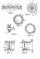
- a rollerway conveyor has a plurality of rollers mounted between parallel rails 1 and 2 on a corresponding plurality of parallel axles 3, with a roller 4 on each axle 3.
- the rollers 4 are mounted for rotation about parallel axes, which axes are in a common plane.
- the plane of the axes may be horizontal for a transfer table, vertical for a side supporting conveyor, or inclined in a conveying direction for an undriven gravity conveyor, for example.
- the rollers 4 form an outer support plane parellel to the plane of the axes, which support plane coincides with an outermost portion of each roller 4.
- Each roller 4 comprises a wheel subassembly 5, for example as shown in Figure 3 and a tyre subassembly, for example as shown in Figure 4.
- a wheel subassembly 5 for example as shown in Figure 3
- a tyre subassembly for example as shown in Figure 4.
- the subassemblies are shown separately.
- the wheel subas ⁇ embly 5 as shown in Figure 3 comprises three basic elements, an inner race 6, an outer race 7, and a plurality of antifriction roller elements 8 therebetween. Each of these elements may take on various forms in accordance with the present invention.
- the inner race 6 may include a shaft 9 that is in one piece with the inner race as shown or separate and drivingly secured thereby (not shown).
- the outer race 7 may comprise a plurality of separate elements as shown or be constructed in one piece (not shown).
- the roller elements 8 may be balls, as shown, or cylindrical rollers (not shown).
- the outer race 7 comprises formed sheet metal portions that are rigidly joined together by rivets 10.
- the inner race 6 and outer race 7 are formed with opposing annular bearing surfaces forming a raceway therebetween to accommodate the antifriction roller elements 8 to form an antifriction bearing. This structure is more fully shown in the above-mentioned U.S.A. patent.
- the outer race includes an outer, generally cylindrical surface 11.
- the tyre subassembly includes a cylindrical rim 12 that has an inner cylindrical surface and an outer cylindrical surface.
- a cylindrical elastomeric tyre 13 has an inner cylindrical surface bonded to the outer cylindrical surface of the rim 12.
- the bonding may be by means of self adhesion, vulcanizing, the application of adhesives, or the application of solvents.
- the tyre 13 is permanently bonded to the outer surface of the rim 12 so as to prevent relative rotation between the two.
- the elastomeric tyre 12 may have its hardness, elasticity, hysteresis properties, etc., chosen according to its purpose and the environment in which it is to be used and in accordance with the loads it is to support.
- a plurality of such tyre subassemblies may be stockpiled with many different types being stockpiled in accordance with the above characteristics that may be desired.
- the critical feature is that all of the tyre subassemblies have substantially the same inner diameter, that all of the wheel subassemblies 5 have substantially the same outer diameter, and that the outer diameter of the wheel subassemblies 5 be larger than the inner diameter of the tyre subassemblies, so as to provide for an interference fit as defined above. Interference fit is the most economic and convenient method, but cementing can also be used, in which case the inner diameter of the tyre subassembly is generally the same as the outer diameter of the wheel subassembly 5.
- the assembly process may be by cooling the wheel subassembly 5 and/or heating the tyre subassembly prior to assembly, so that after assembly the two subassemblies may reach the same temperature and provide for the interference fit. Also, a suitable press may be used for the assembly for a force fit.
- the only means holding the tyre subassembly on the wheel subassembly 5 is the frictional engagement between the wheel subassembly 5 outer surface 11 and the inner surface of the rim 12 as caused by the inherent resiliency of the subassemblies that will cause radial forces that are perpendicular to the engaging surfaces, that is the tyre subassembly will be in tension and the wheel subassembly 5 will be in compression as a result of the interference fit when assembled.
- a tyre subassembly may be selected of a far greater width axially measured than the wheel subassembly 5, so that the load carrying capacity of the elastomeric tyre may then be greater or even approximately equal the load carrying capacity of the bearing, for example, as shown in Figure 5.
- the width of the tyre subassembly (not shown) is equal to or less than the width of the wheel subassembly 5 of Figure 3.
- a further modification is contemplated in accordance with Figure 6, wherein the rim 12" may be extended outwardly in one axial direction and then flared or bent radially outwardly beyond the elastomeric tyre 13" and axially spaced therefrom.
- a support surface of horizontal axis rollers could support articles and engage the sides of the articles with the flared portions 14 to maintain the articles on the rollers.
- Two flights of such rollers could be provided for supporting pallets, for example, and each flight could have a plurality of its rollers constructed in accordance with Figure 6, with the flared portions respectively towards the outside to prevent the pallets from moving laterally with respect to the conveyor that is moving in an axial direction with respect to the roller axes.
- the rim 12' is constructed of a permeable material, such as wire mesh, which may be woven or braided or felted (non-woven) fabric in a tubular form. This porous design allows the elastomer to penetrate the fabric and form an improved bond. It is possible to thus construct the tyre subassembly by cutting off axial lengths of desired length (width of the tyre subassembly) from a moulded tube. Specifically shown is a thin metal rim 12' substantially identical to the metal rim 12 of Figure 4, but with a plurality of holes or apertures 15 extending through it in the radial direction.
- portions of the elastomer 16 extend through the holes 15.
- the elastomer extends through the holes 15 to enter into the interior of the rim 12' against a moulding mandrel to form a thin layer or portions 17 of elastomeric material with a cylindrical inner surface.
- This layer or the portions 17 of elastomeric material inside of the rim will provide a better bond for the tyre and rim, but more importantly, will also compensate for variations in diameters of the wheel subassembly 5 and variations of the diameter of rim interior surface, to form an improved press or interference fit.
- kit of parts for forming conveyor rollers comprising:
- said corresponding first and second subassemblies can be tyre subassemblies differing from each other in at least the axially measured width of both their rims and tyres, with the greater width tyre subassembly having a width substantially greater than the corresponding width of the wheel assemblies of said first set of wheel assemblies.
- the corresponding first and second subassemblies can be tyre subassemblies different from each other at least in that said first set of tyre subassemblies has a rim consisting of a single diameter tube and said second set of tyre subassemblies has rims that extend axially outwardly away from their associated tyres and then radially outwardly to an annular guide portion that extends radially outwardly beyond said tyres for guiding the edges of articles supported on said tyres.
- the corresponding first and second set of subassemblies can be tyre subassemblies differing in at least the elastomeric characteristics of their tyres.
- the difference in elastomeric characteristics can relate to a difference in hysteresis properties of the elastomeric tyres.
- the corresponding first and second subassemblies can be wheel subassemblies differing in bearing structure.
Landscapes
- Engineering & Computer Science (AREA)
- Mechanical Engineering (AREA)
- Rollers For Roller Conveyors For Transfer (AREA)
Applications Claiming Priority (2)
| Application Number | Priority Date | Filing Date | Title |
|---|---|---|---|
| US06/426,112 US5035314A (en) | 1982-09-28 | 1982-09-28 | Gravity roller conveyor construction |
| US426112 | 1982-09-28 |
Publications (2)
| Publication Number | Publication Date |
|---|---|
| EP0104953A2 true EP0104953A2 (de) | 1984-04-04 |
| EP0104953A3 EP0104953A3 (de) | 1985-11-06 |
Family
ID=23689345
Family Applications (1)
| Application Number | Title | Priority Date | Filing Date |
|---|---|---|---|
| EP83305835A Withdrawn EP0104953A3 (de) | 1982-09-28 | 1983-09-28 | Förderrolle und Förderer mit solchen Rollen |
Country Status (10)
| Country | Link |
|---|---|
| US (1) | US5035314A (de) |
| EP (1) | EP0104953A3 (de) |
| JP (1) | JPS59133104A (de) |
| AR (1) | AR231956A1 (de) |
| AU (1) | AU561620B2 (de) |
| BR (1) | BR8305334A (de) |
| CA (1) | CA1205398A (de) |
| MX (1) | MX159574A (de) |
| NZ (1) | NZ205765A (de) |
| ZA (1) | ZA837232B (de) |
Cited By (1)
| Publication number | Priority date | Publication date | Assignee | Title |
|---|---|---|---|---|
| WO2022171541A1 (de) * | 2021-02-12 | 2022-08-18 | Interroll Holding Ag | Förderrolle |
Families Citing this family (12)
| Publication number | Priority date | Publication date | Assignee | Title |
|---|---|---|---|---|
| US5871262A (en) * | 1993-03-05 | 1999-02-16 | Quaglia; Lawrence D. | Precision super high strength wheel, roller and track tread consisting of isoplast or victrex peek with pure carbon fiber content, and with commercial carbon fibers forming an alloy on an improved tread locking insert wheel hub |
| US6336542B1 (en) * | 1998-03-02 | 2002-01-08 | Mintonye, Ii Edwin Arthur | Unidirectional conveyor roller |
| US6250478B1 (en) * | 1999-02-08 | 2001-06-26 | C P Manufacturing Inc. | Stepped disc screens of unequal inclination angles for conveying and grading recycling materials |
| ATE306448T1 (de) | 2000-04-18 | 2005-10-15 | Machf Bollegraaf Appingedam B | Förderer zum fördern von schüttgut |
| KR20030064398A (ko) * | 2000-09-11 | 2003-07-31 | 토소우 에스엠디, 인크 | 내부 냉각 채널을 갖는 스퍼터 타겟의 제조 방법 |
| US7566102B2 (en) * | 2000-09-21 | 2009-07-28 | Innowheel Pty Ltd. | Multiple roller wheel |
| US7318628B2 (en) * | 2000-09-21 | 2008-01-15 | Innowheel Pty Ltd | Multiple directional wheel |
| US6793060B2 (en) * | 2002-04-05 | 2004-09-21 | L.B. International, Inc. | Heavy unit load conveyor wheel |
| US20080011119A1 (en) * | 2006-07-17 | 2008-01-17 | Georg Bartosch | Self-lubricating cam/rail follower |
| US8556279B2 (en) * | 2008-12-08 | 2013-10-15 | Peter Rodney McKinnon | Handtruck |
| WO2011047443A1 (en) | 2009-10-23 | 2011-04-28 | Rotacaster Wheel Ltd | Wheel frame |
| CN107405948B (zh) | 2015-01-06 | 2020-12-08 | 罗塔卡斯特车轮有限公司 | 轮架组件 |
Family Cites Families (23)
| Publication number | Priority date | Publication date | Assignee | Title |
|---|---|---|---|---|
| US3103387A (en) * | 1963-09-10 | Skate wheel with changeable tires | ||
| US934010A (en) * | 1908-09-28 | 1909-09-14 | David Parry | Lifting-dog. |
| US1576924A (en) * | 1923-07-25 | 1926-03-16 | Edward T Malloy | Resiliently-tired wheel |
| US1803357A (en) * | 1929-01-26 | 1931-05-05 | Robins Conveying Belt Co | Pulley |
| FR817977A (fr) * | 1935-10-30 | 1937-09-15 | Mode d'assemblage de pièces par calage | |
| US2241685A (en) * | 1938-07-07 | 1941-05-13 | Chicago Roller Skate Co | Wheel |
| US2241686A (en) * | 1938-07-11 | 1941-05-13 | Chicago Roller Skate Co | Wheel guard |
| US2943889A (en) * | 1956-09-27 | 1960-07-05 | Rapids Standard Co Inc | Caster truck wheels |
| FR1418177A (fr) * | 1964-10-05 | 1965-11-19 | Michelin & Cie | Perfectionnement aux rouleaux pour transporteurs |
| US3443674A (en) * | 1967-11-08 | 1969-05-13 | Andrew T Kornylak | Rollerway and roller therefor |
| DE2052406A1 (de) * | 1970-10-26 | 1972-04-27 | Continental Gummi-Werke Ag, 3000 Hannover | Stütz- oder Pufferring für Tragrollen in Gurtförderanlagen |
| BE794312A (fr) * | 1972-01-24 | 1973-05-16 | Kornylac Co | Galets elastiques de transporteur |
| US3771206A (en) * | 1972-08-11 | 1973-11-13 | Bingham S Co | Can coating roller |
| CA959742A (en) * | 1972-11-29 | 1974-12-24 | Maurice Lacerte | Solid tire wheel |
| DE2306215C3 (de) * | 1973-02-08 | 1975-07-17 | Demag Ag, 4100 Duisburg | Thermische Schrumpfverbindung |
| US3895844A (en) * | 1974-05-22 | 1975-07-22 | Rudolph Merbler | Roller skate wheels |
| US3988045A (en) * | 1975-05-07 | 1976-10-26 | Litton Systems, Inc. | Impact absorbing idler roll assembly |
| DE2533113A1 (de) * | 1975-07-24 | 1977-02-10 | Peter Seitz | Laufrolle fuer stapelkaesten in einem durchlauflagerregal |
| JPS543786A (en) * | 1977-06-10 | 1979-01-12 | Bridgestone Corp | Wheels for running in conduit |
| US4110882A (en) * | 1977-10-21 | 1978-09-05 | Kenhar Products Incorporated | Coating roller |
| US4203509A (en) * | 1978-06-23 | 1980-05-20 | Textron, Inc. | Cargo roller |
| US4218098A (en) * | 1978-07-03 | 1980-08-19 | Burton Elwin E | Skate wheel assembly |
| US4178664A (en) * | 1978-07-17 | 1979-12-18 | Mcloughlin Nelson E | Roller with replaceable sleeve |
-
1982
- 1982-09-28 US US06/426,112 patent/US5035314A/en not_active Expired - Lifetime
-
1983
- 1983-09-27 CA CA000437719A patent/CA1205398A/en not_active Expired
- 1983-09-27 NZ NZ205765A patent/NZ205765A/en unknown
- 1983-09-27 AU AU19604/83A patent/AU561620B2/en not_active Ceased
- 1983-09-28 AR AR294380A patent/AR231956A1/es active
- 1983-09-28 EP EP83305835A patent/EP0104953A3/de not_active Withdrawn
- 1983-09-28 JP JP58180074A patent/JPS59133104A/ja active Granted
- 1983-09-28 ZA ZA837232A patent/ZA837232B/xx unknown
- 1983-09-28 BR BR8305334A patent/BR8305334A/pt unknown
- 1983-09-28 MX MX198901A patent/MX159574A/es unknown
Cited By (2)
| Publication number | Priority date | Publication date | Assignee | Title |
|---|---|---|---|---|
| WO2022171541A1 (de) * | 2021-02-12 | 2022-08-18 | Interroll Holding Ag | Förderrolle |
| US12428238B2 (en) | 2021-02-12 | 2025-09-30 | Interroll Holding Ag | Conveyor roller |
Also Published As
| Publication number | Publication date |
|---|---|
| BR8305334A (pt) | 1984-05-08 |
| JPS59133104A (ja) | 1984-07-31 |
| AU561620B2 (en) | 1987-05-14 |
| CA1205398A (en) | 1986-06-03 |
| NZ205765A (en) | 1987-03-06 |
| US5035314A (en) | 1991-07-30 |
| AU1960483A (en) | 1984-04-05 |
| ZA837232B (en) | 1984-05-30 |
| JPH0313125B2 (de) | 1991-02-21 |
| MX159574A (es) | 1989-07-06 |
| EP0104953A3 (de) | 1985-11-06 |
| AR231956A1 (es) | 1985-04-30 |
Similar Documents
| Publication | Publication Date | Title |
|---|---|---|
| US5035314A (en) | Gravity roller conveyor construction | |
| US4969548A (en) | Compression set limiting gravity conveyor | |
| CA2127349C (en) | Conveyor systems and high durability rollers therefor | |
| US4006810A (en) | Resilient conveyor rollers | |
| EP1378377A2 (de) | Ein gefedertes Leichtrad | |
| AU2002252178B2 (en) | Idler roller for transport conveyor | |
| MXPA04001207A (es) | Montaje de interconexion resistente al desgaste, en particular cadena o cojinete de bolas resistente al desgaste. | |
| CN109723729B (zh) | 带胶粘挡圈的异型免维护单列圆锥滚子轴承的装配工艺 | |
| US20130337986A1 (en) | Lightweight conveyor roller | |
| US6082528A (en) | Conveyor roller | |
| US20120045156A1 (en) | Bearing assembly for a support roller | |
| US20200024076A1 (en) | Conveyor roller with conical tapered element | |
| US5586639A (en) | Powered roller conveyer for light loads | |
| NZ217095A (en) | Conveyor roller:elastomer tyre bonded to rigid ring bonded to inner wheel | |
| DE1052198T1 (de) | Förderer für die Industrie zum Fördern von Bauteilen in grossen Mengen | |
| US4379503A (en) | Gravity rollerway conveyor | |
| US8851264B2 (en) | Roller for conveying glass substrate and roller axle assembly | |
| US4802519A (en) | Rubber tired roller bearing | |
| US3988045A (en) | Impact absorbing idler roll assembly | |
| KR20050074497A (ko) | 컨베이어 및 분말 페인트 포집 시스템 및 방법 | |
| CA1070252A (en) | Gravity rollerway conveyor | |
| US7341138B1 (en) | Conveyor idle roller assembly | |
| WO2017034386A2 (en) | An improved former holder assembly | |
| JP2023080518A (ja) | ローラ保護リングおよびその組み付け方法 | |
| US20040144616A1 (en) | Multi-friction roller for a material handling system |
Legal Events
| Date | Code | Title | Description |
|---|---|---|---|
| PUAI | Public reference made under article 153(3) epc to a published international application that has entered the european phase |
Free format text: ORIGINAL CODE: 0009012 |
|
| AK | Designated contracting states |
Designated state(s): AT BE CH DE FR GB IT LI NL SE |
|
| PUAL | Search report despatched |
Free format text: ORIGINAL CODE: 0009013 |
|
| AK | Designated contracting states |
Designated state(s): AT BE CH DE FR GB IT LI NL SE |
|
| 17P | Request for examination filed |
Effective date: 19860424 |
|
| 17Q | First examination report despatched |
Effective date: 19861027 |
|
| STAA | Information on the status of an ep patent application or granted ep patent |
Free format text: STATUS: THE APPLICATION IS DEEMED TO BE WITHDRAWN |
|
| 18D | Application deemed to be withdrawn |
Effective date: 19880421 |
|
| RIN1 | Information on inventor provided before grant (corrected) |
Inventor name: KORNYLAK, ANDREW T. |