EP0104792B1 - Procédé de fabrication d'un noyau pour bobine d'allumage - Google Patents
Procédé de fabrication d'un noyau pour bobine d'allumage Download PDFInfo
- Publication number
- EP0104792B1 EP0104792B1 EP83305023A EP83305023A EP0104792B1 EP 0104792 B1 EP0104792 B1 EP 0104792B1 EP 83305023 A EP83305023 A EP 83305023A EP 83305023 A EP83305023 A EP 83305023A EP 0104792 B1 EP0104792 B1 EP 0104792B1
- Authority
- EP
- European Patent Office
- Prior art keywords
- laminated member
- center leg
- laminated
- outer legs
- air gap
- Prior art date
- Legal status (The legal status is an assumption and is not a legal conclusion. Google has not performed a legal analysis and makes no representation as to the accuracy of the status listed.)
- Expired
Links
- 238000004519 manufacturing process Methods 0.000 title claims description 6
- 238000005452 bending Methods 0.000 claims description 4
- 238000012544 monitoring process Methods 0.000 claims description 4
- 238000000034 method Methods 0.000 description 7
- 230000008569 process Effects 0.000 description 5
- 238000004804 winding Methods 0.000 description 5
- 239000000463 material Substances 0.000 description 3
- 238000003475 lamination Methods 0.000 description 2
- 230000009467 reduction Effects 0.000 description 2
- 238000003466 welding Methods 0.000 description 2
- 229910000976 Electrical steel Inorganic materials 0.000 description 1
- 239000000853 adhesive Substances 0.000 description 1
- 230000001070 adhesive effect Effects 0.000 description 1
- 230000015572 biosynthetic process Effects 0.000 description 1
- 230000008859 change Effects 0.000 description 1
- 238000002485 combustion reaction Methods 0.000 description 1
- 230000000694 effects Effects 0.000 description 1
- 230000004907 flux Effects 0.000 description 1
- 238000005755 formation reaction Methods 0.000 description 1
- 239000011261 inert gas Substances 0.000 description 1
- 239000012212 insulator Substances 0.000 description 1
- 230000007246 mechanism Effects 0.000 description 1
- 239000000203 mixture Substances 0.000 description 1
- 230000000717 retained effect Effects 0.000 description 1
- WFKWXMTUELFFGS-UHFFFAOYSA-N tungsten Chemical compound [W] WFKWXMTUELFFGS-UHFFFAOYSA-N 0.000 description 1
- 229910052721 tungsten Inorganic materials 0.000 description 1
- 239000010937 tungsten Substances 0.000 description 1
Images
Classifications
-
- H—ELECTRICITY
- H01—ELECTRIC ELEMENTS
- H01F—MAGNETS; INDUCTANCES; TRANSFORMERS; SELECTION OF MATERIALS FOR THEIR MAGNETIC PROPERTIES
- H01F27/00—Details of transformers or inductances, in general
- H01F27/24—Magnetic cores
- H01F27/245—Magnetic cores made from sheets, e.g. grain-oriented
-
- H—ELECTRICITY
- H01—ELECTRIC ELEMENTS
- H01F—MAGNETS; INDUCTANCES; TRANSFORMERS; SELECTION OF MATERIALS FOR THEIR MAGNETIC PROPERTIES
- H01F3/00—Cores, Yokes, or armatures
- H01F3/10—Composite arrangements of magnetic circuits
- H01F3/14—Constrictions; Gaps, e.g. air-gaps
-
- H—ELECTRICITY
- H01—ELECTRIC ELEMENTS
- H01F—MAGNETS; INDUCTANCES; TRANSFORMERS; SELECTION OF MATERIALS FOR THEIR MAGNETIC PROPERTIES
- H01F41/00—Apparatus or processes specially adapted for manufacturing or assembling magnets, inductances or transformers; Apparatus or processes specially adapted for manufacturing materials characterised by their magnetic properties
- H01F41/02—Apparatus or processes specially adapted for manufacturing or assembling magnets, inductances or transformers; Apparatus or processes specially adapted for manufacturing materials characterised by their magnetic properties for manufacturing cores, coils, or magnets
- H01F41/0206—Manufacturing of magnetic cores by mechanical means
- H01F41/0233—Manufacturing of magnetic circuits made from sheets
-
- Y—GENERAL TAGGING OF NEW TECHNOLOGICAL DEVELOPMENTS; GENERAL TAGGING OF CROSS-SECTIONAL TECHNOLOGIES SPANNING OVER SEVERAL SECTIONS OF THE IPC; TECHNICAL SUBJECTS COVERED BY FORMER USPC CROSS-REFERENCE ART COLLECTIONS [XRACs] AND DIGESTS
- Y10—TECHNICAL SUBJECTS COVERED BY FORMER USPC
- Y10T—TECHNICAL SUBJECTS COVERED BY FORMER US CLASSIFICATION
- Y10T29/00—Metal working
- Y10T29/49—Method of mechanical manufacture
- Y10T29/49002—Electrical device making
- Y10T29/49004—Electrical device making including measuring or testing of device or component part
-
- Y—GENERAL TAGGING OF NEW TECHNOLOGICAL DEVELOPMENTS; GENERAL TAGGING OF CROSS-SECTIONAL TECHNOLOGIES SPANNING OVER SEVERAL SECTIONS OF THE IPC; TECHNICAL SUBJECTS COVERED BY FORMER USPC CROSS-REFERENCE ART COLLECTIONS [XRACs] AND DIGESTS
- Y10—TECHNICAL SUBJECTS COVERED BY FORMER USPC
- Y10T—TECHNICAL SUBJECTS COVERED BY FORMER US CLASSIFICATION
- Y10T29/00—Metal working
- Y10T29/49—Method of mechanical manufacture
- Y10T29/49002—Electrical device making
- Y10T29/4902—Electromagnet, transformer or inductor
- Y10T29/49073—Electromagnet, transformer or inductor by assembling coil and core
-
- Y—GENERAL TAGGING OF NEW TECHNOLOGICAL DEVELOPMENTS; GENERAL TAGGING OF CROSS-SECTIONAL TECHNOLOGIES SPANNING OVER SEVERAL SECTIONS OF THE IPC; TECHNICAL SUBJECTS COVERED BY FORMER USPC CROSS-REFERENCE ART COLLECTIONS [XRACs] AND DIGESTS
- Y10—TECHNICAL SUBJECTS COVERED BY FORMER USPC
- Y10T—TECHNICAL SUBJECTS COVERED BY FORMER US CLASSIFICATION
- Y10T29/00—Metal working
- Y10T29/49—Method of mechanical manufacture
- Y10T29/49002—Electrical device making
- Y10T29/4902—Electromagnet, transformer or inductor
- Y10T29/49075—Electromagnet, transformer or inductor including permanent magnet or core
- Y10T29/49078—Laminated
Definitions
- This invention relates to a method of making a laminated core of an ignition coil for use in the spark ignition system of an internal combustion engine.
- a preferred form for such a core is a stack of laminations in a generally rectangular ring having a central leg extending from one side of said ring across the central opening thereof to the other side and also including an air gap.
- the primary and secondary windings of the ignition coil are wound on the central leg with the remainder of the coil providing a return flux path to complete the magnetic circuit.
- Such a core is generally manufactured by stacking laminations into two parts: the first part in the shape of an E with central and outer legs and the second part in the shape of an E with shorter legs or in the shape of a bar capable of spanning or just fitting within the outer legs of the first piece.
- a choke for the ballast unit of a fluorescent lamp is disclosed in DE-A-2 950 727 which is made up of a first laminated member having an E-shape with equal length outer legs and a shorter center leg, with a coil of electrically conducting wire surrounding said center leg, and a second laminated member having a bar shape and being oriented perpendicular to an end surface of the center leg of the first laminated member and being spaced therefrom to form an air gap, there being inclined surfaces on either end of said second laminated member which are engageable with respective inclined, hooked formations on said outer legs so as to allow wedging of the second laminated member into a predetermined position between said outer legs of said first laminated member.
- US-A-3 522 569 discloses a method of making a core having at least two core sections and a coil carried on the sections, with each core section having at least one leg disposed in juxtaposed relation to, and spaced from, a leg of the other core section to provide a gap therebetween.
- the method involves adjustment of the core sections relative to one another to adjust the size of this gap whilst monitoring an electrical characteristic of the core that varies according to the gap spacing by means of the coil, followed by the bridging of the adjusted gap by a re-inforced adhesive material in order to retain the core sections in a fixed position relative to one another.
- a method of making a laminated core according to the present invention comprises the steps of: making an E-shaped first laminated member having a pair of resiliently bendable outer legs with oblique surfaces on the inner free ends thereof and further having a shorter center leg, said oblique surfaces forming a first angle with a surface of said center leg which angle increases with outward bending of the outer legs; assembling a coil of electrically conducting wire around said center leg; making a bar-shaped second laminated member having oblique surfaces on each end thereof, said oblique surfaces, when the second laminated member is oriented perpendicularly to the first laminated member, forming a second angle with said surface of the center leg of the first laminated member at least as great as the first angle through the total range of outward bending of the outer legs of the first laminated member achieved in the following steps; orienting the second laminated member perpendicularly to the center leg of the first laminated member with at least portions of the respective ob
- the first laminated member has an E shape with equal length outer legs having oblique surfaces on the inner free end thereof and a shorter center leg.
- the second laminated member has a bar shape with oblique faces at each end thereof corresponding to the oblique faces of the outer legs of the first laminated member when oriented perpendicularly to the center leg thereof.
- the oblique faces of the second laminated member form angles with respect to the center leg of the first laminated member which are greater before final assembly and at least as great after final assembly as the corresponding angles of the oblique faces of the first laminated member.
- the second laminated member is advanced towards the center leg of the first laminated member with the oblique faces co-operating to bend the outer legs of the first laminated member slightly outwards away from the center leg to generate a spring-like restoring force to stabilize the relative positions of the members and the properties of the core are monitored by means of the ignition coil; and advancement of the second laminated member is halted and the two members welded together when such properties are within the desired limits.
- the difference in the angles of the oblique faces of the two laminated members before assembly are sufficiently great that, in the assembled core, the angles formed by the oblique faces of the second laminated member are still at least as great as those of the first laminated member.
- first and second laminated members 10 and 30 may be made, for example, of multiple laminated layers of 0.254 mm (0.010 inch) thick M-3 grain oriented, electrical steel with a C-5 core plate, although similar materials are acceptable.
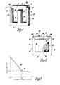
- First laminated member 10 has an E shape with a base 11, a central leg 12 projecting perpendicularly from the center of base 11, and a pair of outer legs 13 and 14 extending from the opposite ends of base 11 in the same direction of center leg 12 and parallel thereto with first laminated member 10 in the unassembled stage.
- Center leg 12 is shorter than the equal length outer legs 13 and 14 and has a flat end surface 15 which is perpendicular to an imaginary axis running straight through the center of the center leg 12 perpendicular to base 11.
- Each of the outer legs 13 and 14 is provided, on its inner free end facing center leg 12, with an oblique surface, which oblique surfaces are number 16 and 17 for legs 13 and 14, respectively, in Figure 1.
- These oblique surfaces 16 and 17 form identical angles of 29°, when first laminated member 10 is in its unassembled state, with the planes of the inner sides 18 and 19 of center leg 12 which are themselves parallel with the imaginary axis through the center of center leg 12.
- Second laminated member 30 is in the shape of a bar and is shown in Figure 1 as being oriented perpendicularly to the imaginary axis through the center of center leg 12 of first laminated member 10.
- Second laminated member 30 has a lower surface 31 which, in the previously described orientation, is parallel with end surface 15 of center leg 12 of first laminated member 10.
- Second laminated member 30 further has, at the ends thereof, oblique surfaces 32 and 33 adjacent the oblique surfaces 16 and 17, respectively, of first laminated member 10.
- the length of second laminated member 30 is greater at the upper surface 34 thereof than the distance between the upper edges 16' and 17' of oblique surfaces 16 and 17; but its length at the lower surface 31 is less than the distance between edges 16' and 17'.
- Oblique surfaces 32 and 33 form identical angles of 30° with the planes of surfaces 18 and 19 of center leg 12 of first laminated member 10. Therefore, if second laminated member 30 is advanced toward the center leg 12 of first laminated member 10 with its perpendicular orientation retained, edges 16' and 17' of the outer legs 13 and 14, respectively, of first laminated member 10 will eventually engage oblique-surfaces 32 and 33 of second laminated member 30. Additional movement of the second laminated member 30 toward the center leg 12 of first laminated member 10 can only be accomplished against the spring force of the outer legs 13 and 14 of first laminated member 10 as they are bent outward by the oblique surfaces 32 and 33 of the advancing second laminated member 30.
- the main air gap is that between surface 15 of center leg 12 of first laminated member 10 and the lower surface 31 of second laminated member 30.
- the dimensions of the first and second laminated members 10 and 30 are such that the total air gap at this point is no greater than the desired air gap for the assembled core.
- first laminated member 10 With appropriate insulators and other parts as shown in Figure 2.
- This coil is shown only in representative form in Figure 2, since it actually comprises a pair of coil windings forming a transformer with an annularly large secondary coil of many turns surrounding an annularly thin primary coil of a much smaller number of turns as is well known in the art of ignition coils.
- the precise structure and composition of the coil or transformer 25 is irrelevant to this invention as long as it is in place around center leg 12.
- the inductance of the core may be measured by the application of current to one of the windings. Since the inductance varies with the total effective air gap, this total effective air gap can be effectively monitored during the final assembly process.
- second laminated member 30 is oriented perpendicularly to the center leg 12 of first laminated member 10 as shown in Figure 1 as described above and advanced as previously described until the monitored total effective air gap reaches the desired value.
- the fist laminated member 10 may be held stationary in a proper fixture while the second laminated member 30 is advanced against the increasing spring force generated by the outwardly bent outer legs 13 and 14 of first laminated member 10. This increasing spring force contributes to the smoothness of operation of the assembling fixture, since it takes up any possible free play or slack in the mechanism and helps stabilize the members.
- the second laminated member When the desired total effective air gap is obtained, the second laminated member may be welded across the full width thereof at each end to the adjacent outer leg of the first laminated member, as shown at reference numeral 28, with a tungsten inert gas welding electrode.
- a tungsten inert gas welding electrode As a practical matter, to allow for some springback in the completed and welded assembly due to the spring force of outer legs 13 and 14 of first laminated member 10, it may be necessary to advance the second laminated member 30 a predetermined distance past the point of desired total effective air gap before welding takes place so that the desired total effective air gap will be obtained by the finished assembly after springback.
- the assembly of the core while varying the air gap and monitoring the inductance of the core and winding permits the magnetic and electrical characteristics of the ignition coil to be determined during this final assembly and thus reduces scrappage, regardless of dimensional and material variations in the various parts of the assembly.
- the oblique surfaces of the laminated members facilitate the easy fitting together of the parts and enable the spring force of the outer legs of the E shaped laminated member to help stabilize the members and ensure good physical engagement of the members for minimal secondary air gaps and a strong, stable final assembly.
Landscapes
- Engineering & Computer Science (AREA)
- Power Engineering (AREA)
- Manufacturing & Machinery (AREA)
- Chemical & Material Sciences (AREA)
- Composite Materials (AREA)
- Ignition Installations For Internal Combustion Engines (AREA)
- Manufacturing Cores, Coils, And Magnets (AREA)
Claims (1)
- Procédé de réalisation d'un noyau feuilleté pour bobine d'allumage présentant un entrefer prédéterminé, du type consistant à réaliser un premier élément feuilleté en forme de E (10) qui comporte deux branches extérieures (13, 14) qui peuvent fléchir élastiquement et offrent des surfaces obliques (16, 17) sur leurs extrémités libres intérieures et qui comporte en outre une branche centrale plus courte (12), lesdites surfaces obliques (16, 17) formant avec une surface (15) de cette branche centrale (12) un premier angle qui augmente lorsque les branches extérieures fléchissent vers l'extérieur, à assembler une bobine (25) en fil conducteur de l'électricité autour de cette branche centrale (12), à réaliser un second élément feuilleté (30) qui est en forme de barre et qui offre à chacune de ses extrémités des surfaces obliques (32, 33) qui, lorsque ce second élément feuilleté (30) est orienté perpendiculairement au premier élément feuilleté (10), forment avec ladite surface (15) de la branche centrale (12) de ce premier élément (10), un second angle qui est au moins aussi grand que le premier angle surtout le domaine complet de flexion vers l'extérieur des branches extérieures (13, 14) de ce premier élément, caractérisé en ce que l'on oriente le second élément feuilleté (30) perpendiculairement à la branche centrale (12) du premier élément feuilleté (10) en faisant venir en contact matériel les unes avec les autres au moins certaines parties des surfaces obliques associées (16, 32; .17, 33) de ces éléments feuilletés de façon à constituer un circuit magnétique présentant un entrefer entre ladite surface (15) de la branche centrale (12) et le second élément feuilleté (30), à faire avancer ce second élément (30) en direction de la branche centrale (12) du premier élément (10), de façon à réduire cet entrefer, à l'encontre de la force de rappel produite par les branches extérieures (13, 14) qui sont fléchies élastiquement vers l'extérieur sous l'effet desdites surfaces obliques en contact (16, 32; 17,33), tout en surveillant, grâce à ladite bobine (25), les valeurs d'un paramètre physique indicateur d'une caractéristique magnétique ou électrique voulue du noyau, et à ne solidariser de façon permanente les surfaces associées (32, 33) du second élément feuilleté (30) sur les surfaces correspondantes (16, 17) des branches extérieures (13, 14) du premier élément (10) que lorsque ledit paramètre indique que l'on a atteint la caractéristique magnétique ou électrique voulue du noyau.
Applications Claiming Priority (2)
| Application Number | Priority Date | Filing Date | Title |
|---|---|---|---|
| US424465 | 1982-09-27 | ||
| US06/424,465 US4480377A (en) | 1982-09-27 | 1982-09-27 | Method of making an ignition coil core |
Publications (2)
| Publication Number | Publication Date |
|---|---|
| EP0104792A1 EP0104792A1 (fr) | 1984-04-04 |
| EP0104792B1 true EP0104792B1 (fr) | 1987-03-18 |
Family
ID=23682718
Family Applications (1)
| Application Number | Title | Priority Date | Filing Date |
|---|---|---|---|
| EP83305023A Expired EP0104792B1 (fr) | 1982-09-27 | 1983-08-31 | Procédé de fabrication d'un noyau pour bobine d'allumage |
Country Status (5)
| Country | Link |
|---|---|
| US (1) | US4480377A (fr) |
| EP (1) | EP0104792B1 (fr) |
| JP (1) | JPS5978516A (fr) |
| CA (1) | CA1192636A (fr) |
| DE (1) | DE3370402D1 (fr) |
Families Citing this family (14)
| Publication number | Priority date | Publication date | Assignee | Title |
|---|---|---|---|---|
| JPH0715853B2 (ja) * | 1986-11-21 | 1995-02-22 | 日本電装株式会社 | エネルギ−蓄積型点火コイル |
| US4706639A (en) * | 1986-12-04 | 1987-11-17 | General Motors Corporation | Integrated direct ignition module |
| US5073766A (en) * | 1990-11-16 | 1991-12-17 | Square D Company | Transformer core and method for stacking the core |
| US5218936A (en) * | 1992-11-13 | 1993-06-15 | Ford Motor Company | Ignition system including spark distribution cassette and ignition coil |
| US5469124A (en) * | 1994-06-10 | 1995-11-21 | Westinghouse Electric Corp. | Heat dissipating transformer coil |
| US6650217B1 (en) * | 1997-03-07 | 2003-11-18 | Koninklijke Philips Electronics N.V. | Low profile magnetic component with planar winding structure having reduced conductor loss |
| DE10132718A1 (de) * | 2001-07-05 | 2003-02-13 | Abb T & D Tech Ltd | Verfahren zum Bewickeln eines Dreiphasen-Kabeltransformators mit Koaxialkabel und Wickelvorrichtung hierzu |
| US10431367B2 (en) * | 2005-09-22 | 2019-10-01 | Radial Electronics, Inc. | Method for gapping an embedded magnetic device |
| CN2924745Y (zh) * | 2006-01-26 | 2007-07-18 | 杨建文 | 电子镇流器 |
| EP1887586A1 (fr) * | 2006-08-09 | 2008-02-13 | Magneti Marelli Holding S.p.A. | Bobine d'allumage et son procédé d'assemblage |
| EP1887589A1 (fr) * | 2006-08-09 | 2008-02-13 | Magneti Marelli Holding S.p.A. | Bobine d'allumage |
| US7834737B2 (en) * | 2007-09-10 | 2010-11-16 | Delphi Technologies, Inc. | Ignition apparatus having bonded steel wire central core |
| CN107533903B (zh) * | 2015-05-13 | 2019-11-22 | 三菱电机株式会社 | 点火线圈 |
| EP4290537A1 (fr) * | 2022-06-10 | 2023-12-13 | FRONIUS INTERNATIONAL GmbH | Bobine d'inductance et procédé de fabrication d'une telle bobine d'inductance |
Family Cites Families (11)
| Publication number | Priority date | Publication date | Assignee | Title |
|---|---|---|---|---|
| US2712084A (en) * | 1955-06-28 | Motor stator assembly | ||
| US1748993A (en) * | 1926-10-19 | 1930-03-04 | Western Electric Co | Electrical coil and method of manufacturing it |
| US1841685A (en) * | 1930-08-27 | 1932-01-19 | Joseph G Sola | Transformer |
| US2220126A (en) * | 1937-01-13 | 1940-11-05 | Hartford Nat Bank & Trust Co | Inductance coil |
| US2439277A (en) * | 1944-01-15 | 1948-04-06 | Bendix Aviat Corp | High-frequency coil |
| US3209294A (en) * | 1962-10-23 | 1965-09-28 | Westinghouse Electric Corp | Magnetic core structures |
| DE1613628A1 (de) * | 1967-03-20 | 1970-07-30 | Blum Eisen & Metallind | Zweiteiliger Eisenkern,insbesondere fuer Transformatoren |
| US3522569A (en) * | 1967-07-20 | 1970-08-04 | Gen Electric | Magnetic core and coil assembly having a gap which is fixed by a reinforced adhesive layer spanning the gap |
| DE2950727C2 (de) * | 1979-12-17 | 1983-11-03 | May & Christe Gmbh, Transformatorenwerke, 6370 Oberursel | Drosselspule für das Vorschaltgerät von Leuchtstofflampen |
| DE3069353D1 (en) * | 1980-06-30 | 1984-11-08 | Clarel Sa | Laminated magnetic circuit with air gap, and method of adjusting the air gap |
| DE3030641A1 (de) * | 1980-08-13 | 1982-04-01 | Siemens AG, 1000 Berlin und 8000 München | Unter einschluss von kleinen eisenteilchen geformter magnetkern und verfahren zur herstellung des magnetkerns |
-
1982
- 1982-09-27 US US06/424,465 patent/US4480377A/en not_active Expired - Lifetime
-
1983
- 1983-07-11 CA CA000432182A patent/CA1192636A/fr not_active Expired
- 1983-08-31 EP EP83305023A patent/EP0104792B1/fr not_active Expired
- 1983-08-31 DE DE8383305023T patent/DE3370402D1/de not_active Expired
- 1983-09-27 JP JP58177189A patent/JPS5978516A/ja active Granted
Also Published As
| Publication number | Publication date |
|---|---|
| DE3370402D1 (en) | 1987-04-23 |
| US4480377A (en) | 1984-11-06 |
| JPH0144003B2 (fr) | 1989-09-25 |
| CA1192636A (fr) | 1985-08-27 |
| JPS5978516A (ja) | 1984-05-07 |
| EP0104792A1 (fr) | 1984-04-04 |
Similar Documents
| Publication | Publication Date | Title |
|---|---|---|
| EP0104792B1 (fr) | Procédé de fabrication d'un noyau pour bobine d'allumage | |
| US2962679A (en) | Coaxial core inductive structures | |
| EP0412678B1 (fr) | Bobine d'allumage | |
| GB2099635A (en) | Transformers for battery charging systems | |
| HK70085A (en) | Transformer | |
| EP0716436B1 (fr) | Bobine d'allumage pour un moteur à combustion interne | |
| US4761630A (en) | Butt-lap-step core joint | |
| US20060158303A1 (en) | Snap-together choke and transformer assembly for an electric arc welder | |
| GB2141288A (en) | Transformer | |
| US4683919A (en) | Apparatus and method for fabricating a high voltage winding for a toroidal transformer | |
| US4345229A (en) | Amorphous metal ballasts and reactors | |
| US3025483A (en) | Magnetic core | |
| US4064473A (en) | Transformer with windings in helical slots of core | |
| JPH02192705A (ja) | 内鉄形変圧器 | |
| JPH0636950A (ja) | 内燃機関用点火コイルの磁心 | |
| JPH0124893Y2 (fr) | ||
| US3252118A (en) | Electromagnetic induction apparatus | |
| US5660756A (en) | High-voltage transformer for a microwave oven power supply | |
| US3321822A (en) | Wound core method | |
| US4288773A (en) | Amorphous metal ballasts and reactors | |
| JPH0729823U (ja) | 交流アーク溶接機用漏洩トランス | |
| JPH08335523A (ja) | 点火コイル | |
| JPS6130253Y2 (fr) | ||
| JPS6339955Y2 (fr) | ||
| WO2026047849A1 (fr) | Transformateur |
Legal Events
| Date | Code | Title | Description |
|---|---|---|---|
| PUAI | Public reference made under article 153(3) epc to a published international application that has entered the european phase |
Free format text: ORIGINAL CODE: 0009012 |
|
| AK | Designated contracting states |
Designated state(s): DE FR GB |
|
| 17P | Request for examination filed |
Effective date: 19840918 |
|
| GRAA | (expected) grant |
Free format text: ORIGINAL CODE: 0009210 |
|
| AK | Designated contracting states |
Kind code of ref document: B1 Designated state(s): DE FR GB |
|
| REF | Corresponds to: |
Ref document number: 3370402 Country of ref document: DE Date of ref document: 19870423 |
|
| ET | Fr: translation filed | ||
| PLBE | No opposition filed within time limit |
Free format text: ORIGINAL CODE: 0009261 |
|
| STAA | Information on the status of an ep patent application or granted ep patent |
Free format text: STATUS: NO OPPOSITION FILED WITHIN TIME LIMIT |
|
| 26N | No opposition filed | ||
| PG25 | Lapsed in a contracting state [announced via postgrant information from national office to epo] |
Ref country code: DE Effective date: 19880503 |
|
| GBPC | Gb: european patent ceased through non-payment of renewal fee | ||
| PG25 | Lapsed in a contracting state [announced via postgrant information from national office to epo] |
Ref country code: FR Free format text: LAPSE BECAUSE OF NON-PAYMENT OF DUE FEES Effective date: 19880531 |
|
| REG | Reference to a national code |
Ref country code: FR Ref legal event code: ST |
|
| PG25 | Lapsed in a contracting state [announced via postgrant information from national office to epo] |
Ref country code: GB Free format text: LAPSE BECAUSE OF NON-PAYMENT OF DUE FEES Effective date: 19881122 |