EP0103825A2 - Elastic coupling - Google Patents
Elastic coupling Download PDFInfo
- Publication number
- EP0103825A2 EP0103825A2 EP83108915A EP83108915A EP0103825A2 EP 0103825 A2 EP0103825 A2 EP 0103825A2 EP 83108915 A EP83108915 A EP 83108915A EP 83108915 A EP83108915 A EP 83108915A EP 0103825 A2 EP0103825 A2 EP 0103825A2
- Authority
- EP
- European Patent Office
- Prior art keywords
- teeth
- coupling
- tooth
- clutch
- gear wheels
- Prior art date
- Legal status (The legal status is an assumption and is not a legal conclusion. Google has not performed a legal analysis and makes no representation as to the accuracy of the status listed.)
- Granted
Links
Images
Classifications
-
- F—MECHANICAL ENGINEERING; LIGHTING; HEATING; WEAPONS; BLASTING
- F16—ENGINEERING ELEMENTS AND UNITS; GENERAL MEASURES FOR PRODUCING AND MAINTAINING EFFECTIVE FUNCTIONING OF MACHINES OR INSTALLATIONS; THERMAL INSULATION IN GENERAL
- F16D—COUPLINGS FOR TRANSMITTING ROTATION; CLUTCHES; BRAKES
- F16D3/00—Yielding couplings, i.e. with means permitting movement between the connected parts during the drive
- F16D3/50—Yielding couplings, i.e. with means permitting movement between the connected parts during the drive with the coupling parts connected by one or more intermediate members
- F16D3/54—Couplings comprising a chain or strip surrounding two wheels arranged side by side and provided with teeth or the equivalent
-
- F—MECHANICAL ENGINEERING; LIGHTING; HEATING; WEAPONS; BLASTING
- F16—ENGINEERING ELEMENTS AND UNITS; GENERAL MEASURES FOR PRODUCING AND MAINTAINING EFFECTIVE FUNCTIONING OF MACHINES OR INSTALLATIONS; THERMAL INSULATION IN GENERAL
- F16D—COUPLINGS FOR TRANSMITTING ROTATION; CLUTCHES; BRAKES
- F16D3/00—Yielding couplings, i.e. with means permitting movement between the connected parts during the drive
- F16D3/50—Yielding couplings, i.e. with means permitting movement between the connected parts during the drive with the coupling parts connected by one or more intermediate members
- F16D3/56—Yielding couplings, i.e. with means permitting movement between the connected parts during the drive with the coupling parts connected by one or more intermediate members comprising elastic metal lamellae, elastic rods, or the like, e.g. arranged radially or parallel to the axis, the members being shear-loaded collectively by the total load
- F16D3/58—Yielding couplings, i.e. with means permitting movement between the connected parts during the drive with the coupling parts connected by one or more intermediate members comprising elastic metal lamellae, elastic rods, or the like, e.g. arranged radially or parallel to the axis, the members being shear-loaded collectively by the total load the intermediate members being made of rubber or like material
-
- F—MECHANICAL ENGINEERING; LIGHTING; HEATING; WEAPONS; BLASTING
- F16—ENGINEERING ELEMENTS AND UNITS; GENERAL MEASURES FOR PRODUCING AND MAINTAINING EFFECTIVE FUNCTIONING OF MACHINES OR INSTALLATIONS; THERMAL INSULATION IN GENERAL
- F16D—COUPLINGS FOR TRANSMITTING ROTATION; CLUTCHES; BRAKES
- F16D3/00—Yielding couplings, i.e. with means permitting movement between the connected parts during the drive
- F16D3/50—Yielding couplings, i.e. with means permitting movement between the connected parts during the drive with the coupling parts connected by one or more intermediate members
- F16D3/72—Yielding couplings, i.e. with means permitting movement between the connected parts during the drive with the coupling parts connected by one or more intermediate members with axially-spaced attachments to the coupling parts
- F16D3/74—Yielding couplings, i.e. with means permitting movement between the connected parts during the drive with the coupling parts connected by one or more intermediate members with axially-spaced attachments to the coupling parts the intermediate member or members being made of rubber or other rubber-like flexible material
Definitions
- the invention relates to an elastic coupling with two to shaft ends arranged, like gears, as well as wel with the two gears overlapping coupling ring - cher abuts a Innnen- or outer surface of an associated sleeve, and the clutch teeth are formed from a sheet, which according to the shape the tooth gaps of the gears is curved, the coupling teeth having the same angular pitch as the teeth of the gears and engaging in the tooth gaps of the gears and the rows of teeth of the gears lying axially next to one another.
- US Pat. No. 2,701,456 describes an elastic coupling in which the coupling toothed ring has a sleeve in which the coupling teeth are held.
- the clutch teeth are made of corrugated sheet metal and they rest on the inner surface of the sleeve.
- the sleeve also has two axially spaced ring surfaces on which the clutch teeth also abut.
- the clutch ring gear is thus firmly clamped in the sleeve.
- the clutch teeth When loaded, the clutch teeth can be deformed and in particular be twisted, with a comparatively high surface pressure between the clutch teeth and the teeth of the gears.
- the coupling must have a large volume. There is no radial movement of the clutch teeth when the load changes.
- the invention has for its object to design a clutch of the type mentioned in such a way that a high torque can be transmitted with a small volume and a good damping effect can be specified in a simple manner.
- the tooth. flanks of the gears and the clutch teeth are flat, that when loaded, the clutch teeth with their first tooth flanks only rest on the tooth flanks of the teeth of one gear and with their other flanks only on the tooth flanks of the teeth of the second gear and that the flank angle of the teeth of the Gears is larger than the friction angle.
- the clutch is free of play.
- the clutch teeth advantageously engage the tooth gaps of the gearwheels from the outside.
- the coupling teeth engage in the tooth gaps of the gearwheels from the inside.
- tooth row of the clutch ring gear is designed as a zigzag plate.
- the two gears and the clutch ring gear have the same number of teeth.
- the row of teeth of the clutch ring gear advantageously has defects which are preferably arranged equidistantly. This omission of individual teeth will be cost-saving, for example, if only a relatively small number of teeth are sufficient to transmit the intended torque and, for constructional or other reasons, an appropriate reduction in the outside diameter of the coupling is out of the question.
- a particularly inexpensive construction and assembly is that the row of teeth at least a gear is designed as a zigzag plate, which is rotatably connected to the coupling hub or directly to the shaft.
- the zigzag plate is advantageously closed and brought to the shaft or coupling hub for pretensioning, wedge-shaped elements being arranged between the zigzag plate and the shaft or coupling hub, the profile of which in each case corresponds to the tooth gaps of the zigzag.
- Zack sheet and the surface of the shaft or coupling hub is adapted.
- the zigzag plate is fixed in a rotationally fixed manner on the gearwheel, since the coupling hub or the shaft has rounded notches on the outer surface which extend in the axial direction and in which the inner edges of the zigzag -Blue sit. Welding is not necessary, since the teeth of the clutch sprocket always press axially inwards and the zigzag plate cannot jump out of the notches if the notches are sufficiently deep.
- a further simplification of the assembly results from the fact that the zigzag plate does not need to be closed, since no forces are transmitted in its circumferential direction. There are even no special coupling hubs if the notches are applied directly to the shaft.
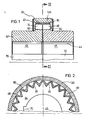
- 1 and 2 consists essentially of an internally toothed clutch sprocket 90 and two externally toothed gears 82 and 84.
- the teeth 46 and 74 of the gears are arranged on two coupling hubs 44 and 42, each for non-rotatable fastening on shaft ends, not shown are provided with a bore 45 and keyways 70.
- An Order of the two gears 82 and 84 made so that they are approximately aligned and immediately next to each other.
- the number and the shape as well as all features of teeth 46 and 74 of the two gear wheels which are characteristic of a toothing are identical and are arranged side by side so that one clutch tooth 48 of the clutch ring gear 90 is in engagement with the teeth 46, 74 of the gear wheels. For this it is necessary that the axial width of the clutch teeth 48 is approximately as large as the common axial extent of the teeth 46 and 74 of the gear wheels.
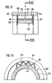
- the structure of the clutch ring gear 90 can best be seen from the cross section according to FIG. 2.
- the clutch sprocket 90 is surrounded by an annular sleeve 120, the axial width of which is somewhat larger than the axial extension of the clutch teeth 48.
- the sleeve 120 is made of metal such as Steel and the clutch teeth 48 are formed by a zigzag plate 80 which is inserted into the annular sleeve 120. At the axial ends of the sleeve 120 there is a ring 47 which extends into the vicinity of the coupling hubs 42, 44. This prevents the ingress of dirt and the escape of lubricant that is introduced between the teeth (see FIG. 1).
- the zigzag plate 80 is folded so that its teeth 81 engage in the tooth spaces of the gears 82 and 84 and thus form the clutch teeth 48 of the clutch ring gear 90.
- the zigzag sheet 80 is preferably made of elastic, resilient material, for example steel; its wall thickness is small in relation to the diameter of the Sleeve 120.
- all teeth have a triangular profile and flat tooth flanks, the tooth tips possibly being rounded.
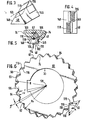
- FIGS. 3 and 4 show a clutch tooth 48 of the clutch ring gear and its interaction with the teeth 46 and 74 of the gears.
- the teeth 46 and 74 are only indicated by the tooth flanks 116 and 118 of the teeth 46 and 74.
- one tooth flank 146 of the clutch tooth 48 bears the tooth flank 116 of a gear tooth
- the other tooth flank 148 of the clutch tooth 48 bears the tooth flank 118 of another gear tooth.
- the two tooth flanks 116 and 118 together form the "virtual tooth gap" whichcycle.In completely filled by the coupling tooth 48 as in FIGS. 3 to 5, the coupling tooth 48 of the simpler D ar- position shown as a solid tooth because, although one of bent sheet metal and is therefore hollow.
- Fig. 4 shows the subject of Fig. 3 in supervision.
- the areas of the tooth flanks 116 and 118 which are in contact with the coupling tooth 48 are here designated with crosses.
- Fig. 6 shows the side view of two gears arranged side by side, e.g. the view of the object of FIG. 1 from the left on a smaller scale, but without the clutch sprocket 90 and without the ring 47, the visible parts of the teeth 46 are dotted.
- the two gear wheels 82 and 84 lying one behind the other are rotated against each other by an angle of rotation.
- the tooth flanks 116 and 118 of the teeth of the two gearwheels form two rows of virtual tooth gaps 50 and 51 with one another.
- the flanks of the larger virtual tooth gap 50 intersect once in a line 62, which can be recognized as a virtual tooth gap tip 62. All of these virtual tooth gap tips 62 lie on the "virtual nut circle" 64, which has the radius rv.
- FIG. 5 now shows how the clutch teeth 48 of the clutch ring gear 90 work together with the virtual tooth spaces 50 of the gear wheels.
- this figure shows a section from the lower half 6 on a larger scale, with a single clutch tooth 48 and the teeth 46, 74 of the gearwheels cooperating therewith being additionally shown.
- the tooth flank 118 of the front gearwheel 74 together with the tooth flank 116 of the rear gearwheel forms a virtual tooth gap which is filled by the clutch tooth 48.
- the tooth flank 148 of the clutch tooth 48 therefore bears against the tooth flank 118 of the front tooth 74, whereas the tooth flank 146 of the clutch tooth 48 bears against the tooth flank 116 of the rear tooth 46.
- the tip of the clutch tooth 48 has no rounding, so that the virtual tooth gap tip 62 ′ coincides with the tip of the clutch tooth 48. If the tip of the coupling tooth 48 were rounded in the usual way, this would not be the case.
- the teeth 46 and 74 act on the clutch tooth 48 with the forces indicated by the arrows 102 and 104. These forces are broken down into tangential components 106 and 108 on the one hand and into radial component 110 on the other. It can be seen that the tangential components 106 and 108 cancel each other out, with the result that no forces act on the coupling tooth 48 in the circumferential direction. This is the reason why the clutch sprocket 90 does not need to transmit any forces in the circumferential direction and can therefore be made thin and elastic without impairing the service life and the performance of the clutch to transmit the highest torques. Only the radial force component 110 acts on the clutch tooth 48 Tooth presses on the sleeve 120 and causes an elastic deformation of the coupling teeth 48 in the region of the sleeve 120.
- the sleeve 120 presses the clutch teeth 48 in cooperation with the restoring force of the elastically deformed clutch teeth in the direction of arrow 114 into the virtual tooth gaps.
- the cutting line 62 moves continuously outwards.
- the root circle radius rv of the virtual tooth gap becomes larger, the clutch teeth 48 are pushed outwards so that the flat tooth flanks slide on one another.
- the radial displacement is possible due to the elastic design of the coupling toothed ring 90, because in the event of a displacement those parts which form the tooth flanks are compressed against the sleeve 120 and elastically deformed in the region lying on the sleeve 120. If necessary, an elastic radial springing of the sleeve also contributes to the displaceability of the clutch teeth 48.
- the two coupling halves connect an engine and a work machine, a very high torque must first be transmitted when starting the engine in order to accelerate the work machine.
- the spring force or deformability of the clutch teeth 48 made of sheet metal is set to be correspondingly soft, the clutch teeth 48 are pressed far outward and this initially results in a relatively large angle of rotation y of the gear wheels.
- the spring force seeks to bring the clutch teeth 48 back into the original shape or position and thus to reduce the angle of rotation. In the stationary operating state, the angle of rotation y then becomes zero or almost zero again.
- the elasticity of the coupling according to the invention is brought about by the radial mobility of the teeth of the coupling toothed ring, the size of this mobility being determined by the elasticity of the zigzag plate, possibly in cooperation with the base body.
- the elastic torsion of the clutch teeth 48 in the gap between the two clutch halves contributes to the torsional elasticity of the clutch.
- the elasticity dampens any torsional vibrations or torsional impacts that may occur.
- the damping characteristic in this case depends on the number of teeth and the flank angle of the teeth of the gears. It applies here that the damping increases with the number of gear teeth, and the damping also increases with a smaller flank angle of the teeth of the gear wheels.
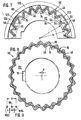
- FIG. 7 shows the upper half of FIG. 1 in a side view from the left without ring 47, the two gear wheels having an angle of rotation which, in contrast to FIG. 1 or 2, is greater than zero.
- the zigzag sheet 80 is shown hatched, although it is not cut. It can be seen that the zigzag plate 80 and the sleeve 120 are pressed radially outwards.
- the clutch sprocket has no clutch teeth 48.
- the zigzag plate 80 on the inside of the sleeve 120 is passed over the virtual tooth gap 50 and a coupling tooth 48 is only formed at the next virtual tooth gap; a virtual tooth gap 50 thus remains free.
- a flaw 122 is shown in an embodiment variant with respect to the zigzag sheet 80.
- the zigzag sheet forms an arc 124 projecting into the virtual tooth gap 50, which, however, does not touch the tooth flanks of the gear wheels.
- This design of the zigzag sheet 80 as an arc 124 in the area of the virtual tooth gap 50 increases the elasticity of the zigzag sheet.
- the defects 122 are arranged in a regular sequence; the distance between two imperfections is 6 teeth of the clutch ring gear 90.
- Fig. 8 the two gears 82 and 84 are shown with their centers M82 and M84 offset by an offset a from each other.
- the sleeve surrounding the zigzag sheet 80 is not shown here.
- the root circle of the virtual tooth gaps remains circular.
- FIG. 9 shows an enlarged view of the center of FIG. 8 and it can be seen that the center 58 of the said base circle halves the offset a almost exactly.
- the teeth 46 of the rear gear 84 are indicated in FIG. 8, as in the other figures, by dots, insofar as they are not covered by the teeth 74 of the front gear 82. It can be seen in FIG. 8 that the teeth 46 are less visible on the left side than on the right side because of the offset a. However, since the center 58 of the root circle of the virtual tooth gap row halves the offset, the offset a is noticeable in the teeth only in half the size. This means that the clutch sprocket 90 makes a radial movement while rotating, but that this only occurs by a / 2. This has the result that the restoring forces, the - jos on the bearings of the shafts is reduced accordingly and the Schwingungsanregun- g s can be halved. Additional sliding takes place on the tooth flanks. For this reason, the clutch requires grease or oil lubrication for high drive power, which can also serve as cooling.
- the tooth flanks 118 form the angle a with one another.
- the tooth flanks 116 likewise form the same angle a with one another.
- tooth gap 50 is delimited on the one hand by a tooth flank 118 and on the other hand by a tooth flank 116.
- These tooth flanks 118 and 116 form a smaller angle a with one another.
- the value of this angle ⁇ corresponds to ⁇ if the angle of rotation ⁇ of the gears is zero.
- the value of ⁇ ab decreases, ie the virtual tooth gap 50 becomes increasingly pointed.
- the flat contact of the clutch teeth not shown in FIG. 6, is achieved here by the elastic suspension of the clutch teeth at the tooth tips, which enables the flank angle of the clutch teeth to be adjusted.
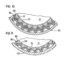
- the gears do not have any coupling hubs, but wedge-shaped elements 32, e.g. made of metal, the inner surfaces 33 of which each lie smoothly on the outer surface of the shafts 31.
- the rows of teeth of the gears are formed by zigzag sheets 180.
- the zigzag plate 180 is closed and placed with pretension over the wedge-shaped elements 32, which can be glued to the shaft for assembly.
- the gearwheel consisting of the wedge-shaped elements 32 and the zigzag plate 180 thus sits directly on the shaft 31 and a coupling hub is therefore not necessary in this very simple construction.
- both gears consist of such wedge-shaped elements 32 with zigzag sheets 180 applied under pretension.
- the row of teeth of the clutch ring gear is also zigzagged.
- Zack plate 80 is formed, which is supported on the annular sleeve 120.
- the zigzag plate 180 is closed to form a ring.
- FIG. 11 A construction which is similar in principle is shown in FIG. 11, but the construction shown there eliminates the wedge-shaped elements 32.
- rounded notches 126 are made in the shaft 31, into which the inwardly directed edges 34 of the zigzag Sheet metal 180, which forms the gear, engage.
- These notches 126 must be sufficiently deep so that the zigzag plate 180 is not torn out of the notches 126 when the torques occur.
- a safety slip clutch can be formed in this way, which separates the two coupled shafts when a certain torque is reached.
- FIG. 11 has the advantage over FIG. 10 that the wedge-shaped elements 32 are omitted.
- FIGS. 12 and 13 show the reverse case, FIG. 12 showing an axial longitudinal section through the upper half of a clutch and FIG. 13 a cross section along the section line XIII-XIII of Fig. 12.
- the coupling hubs 142 and 144 or the shafts to be coupled are then hollow and have at their ends inwardly directed teeth 274 and 276, which form the internally toothed gears 182 and 184.
- the externally toothed clutch ring gear 190 which consists of a zigzag plate 80, which engages in the tooth gaps of the gear wheels, is arranged within the gear wheels 182, 184. Inwardly, the zigzag sheet 80 is supported on an annular sleeve 220, which is optionally elastically deformable.
- the coupling hubs 142, 144 could also be radially resilient, i.e. be elastic to achieve additional spring loading of the teeth.
Abstract
Description
Die Erfindung betrifft eine elastische Kupplung mit zwei auf Wellenenden angeordneten, gleichartigen Zahnrädern, sowie mit einem die beiden Zahnräder überdeckenden Kupplungskranz, wel- cher an einer Innnen- oder Außenfläche einer zugeordneten Hülse anliegt und dessen Kupplungszähne aus einem Blech gebildet sind, welches entsprechend der Gestalt der Zahnlücken der Zahnräder gebogen ist, wobei die Kupplungszähne die gleiche Winkelteilung wie die Zähne der Zahnräder haben und in die Zahnlücken der Zahnräder eingreifen und wobei die Zahnreihen der Zahnräder in axialer Richtung nebeneinander liegen.The invention relates to an elastic coupling with two to shaft ends arranged, like gears, as well as wel with the two gears overlapping coupling ring - cher abuts a Innnen- or outer surface of an associated sleeve, and the clutch teeth are formed from a sheet, which according to the shape the tooth gaps of the gears is curved, the coupling teeth having the same angular pitch as the teeth of the gears and engaging in the tooth gaps of the gears and the rows of teeth of the gears lying axially next to one another.
In der US-PS 2 701 456 ist eine elastische Kupplung beschrieben, bei welcher der Kuppplungszahnkranz eine Hülse aufweist, in welcher die Kupplungszähne gehalten sind. Die Kupplungszähne sind aus gewelltem Blech gefertigt und sie liegen an der Innenfläche der Hülse an. Die Hülse weist ferner zwei in axialer Richtung beabstandete Ringflächen auf, an welchen die Kupplungszähne ebenfalls anliegen. Der Kupplungszahnkranz ist also fest in die Hülse eingespannt. Bei Belastung können die Kupplungszähne deformiert und insbesondere tordiert werden, wobei eine vergleichsweise hohe Flächenpressung zwischen den Kupplungszähnen und den Zähnen der Zahnräder gegeben ist. Für große Drehmomente muß die Kupplung ein großes Bauvolumen aufweisen. Eine radiale Bewegung der Kupplungszähne bei Belastungsänderung tritt nicht ein. Ferner wird aufgrund der genannten starren Einspannung eine radiale Bewegung der Kupplungszähne unterbunden. Zwar wird aufgrund der erläuterten Einspannung des Kupplungszahnkranzes eine gute parallele und koaxiale Ausrichtung der Wellenenden erreicht, doch es wird auch der zulässige Verdrehwinkel zwischen den beiden Wellen entsprechend klein sein.US Pat. No. 2,701,456 describes an elastic coupling in which the coupling toothed ring has a sleeve in which the coupling teeth are held. The clutch teeth are made of corrugated sheet metal and they rest on the inner surface of the sleeve. The sleeve also has two axially spaced ring surfaces on which the clutch teeth also abut. The clutch ring gear is thus firmly clamped in the sleeve. When loaded, the clutch teeth can be deformed and in particular be twisted, with a comparatively high surface pressure between the clutch teeth and the teeth of the gears. For large torques, the coupling must have a large volume. There is no radial movement of the clutch teeth when the load changes. Furthermore, due to the rigid clamping mentioned, a radial movement of the clutch teeth is prevented. Although a good parallel and coaxial alignment of the shaft ends is achieved due to the described clamping of the clutch ring gear, the permissible angle of rotation between the two shafts will also be correspondingly small.
Ferner ist in der US-PS 1 435 141 eine elastische Kupplung beschrieben, bei welcher der Kupplungszahnkranz ebenfalls von einer Hülse umgeben ist. Die Zahnräder weisen jedoch einen vergleichsweise großen axialen Abstand auf und die Kupplungszähne werden bei Belastung in Umfangsrichtung auf Biegung beansprucht. Auch ist der Flankenwinkel der Zähne der Zahnräder relativ klein, so daß eine in radialer Richtung erfolgende Bewegung der Kupplungszähne bei Belastung oder bei Belastungsänderurig nicht erfolgen kann. Eine durch Reibkräfte bedingte Dämpfungswirkung ist praktisch nicht gegeben. Das dieser Kupplung zugrundeliegende Kupplungsprinzip erfordert einen entsprechend großen axialen Abstand der Zahnräder und ein großes Bauvolumen.Furthermore, an elastic coupling is described in US Pat. No. 1,435,141, in which the coupling ring gear is also surrounded by a sleeve. However, the gears have a comparatively large axial distance and the coupling teeth are subjected to bending in the circumferential direction when loaded. The flank angle of the teeth of the gear wheels is also relatively small, so that the clutch teeth cannot move in the radial direction under load or under load changes. There is practically no damping effect due to frictional forces. The coupling principle on which this coupling is based requires a correspondingly large axial distance between the gears and a large structural volume.
Der Erfindung liegt die Aufgabe zugrunde, eine Kupplung der eingangs genannten Art derart auszubilden, daß bei geringem Bauvolumen ein hohes Drehmoment übertragbar ist und eine gute Dämpfungswirkung in einfacher Weise vorgebbar ist.The invention has for its object to design a clutch of the type mentioned in such a way that a high torque can be transmitted with a small volume and a good damping effect can be specified in a simple manner.
Zur Lösung dieser Aufgabe wird vorgeschlagen, daß die Zahn- . flanken der Zahnräder sowie der Kupplungszähne eben ausgebildet sind, daß bei Belastung die Kupplungszähne mit ihren ersten Zahnflanken nur an den Zahnflanken der Zähne des einen Zahnrades und mit ihren anderen Flanken nur an den Zahnflanken der Zähne des zweiten Zahnrades anliegen und daß der Flankenwinkel der Zähne der Zahnräder größer ist als der Reibungswinkel.To solve this problem it is proposed that the tooth. flanks of the gears and the clutch teeth are flat, that when loaded, the clutch teeth with their first tooth flanks only rest on the tooth flanks of the teeth of one gear and with their other flanks only on the tooth flanks of the teeth of the second gear and that the flank angle of the teeth of the Gears is larger than the friction angle.
Durch die Ausbildung der Zahnflanken sämtlicher zusammenwirkender Zähne als ebene Zahnflanken wird eine große Übertragungsfläche bereitgestellt, so daß bei vorgegebener zulässiger Flächenpressung auch ein hohes Drehmoment übertragbar ist. Diese flächenhafte Anlage der ebenen Zahnflanken bleibt auch mit zunehmender Belastung und bei hohen Drehmomenten erhalten. Da der Flankenwinkel der Zähne der Zahnräder größer ist als der Reibungswinkel, können die Kupplungszähne bei Belastungsänderung an den Zahnflanken der zugeordneten Zahnräder gleiten, wobei praktisch keine Deformation der Zahnflanken der Kupplungszähne erfolgt. Eine Deformation erfolgt lediglich im Bereich der Zahnspitzen bzw. der Füße, während die flächenhafte Anlage der Zahnflanken ohne wesentliche Veränderung erhalten bleibt. Die Kupplungszähne erfahren also bei Belastungsänderung eine in radialer Richtung erfolgende Bewegung. Die hierbei auftretenden Reibungskräfte sind für die Dämpfung maßgebend; die Dämpfungscharakteristik ist insbesondere durch den Flankenwinkel und Vorgabe des Reibbeiwertes recht genau vorgebbar. Ferner passen sich die Kupplungszähne bei Belastung in ihrer Formgebung den "virtuellen Zahnlücken" der Zahnräder an. Erfindungsgemäß liegen die Kuppplungszähne bei Belastung jeweils mit ihrer einen Zahnflanke an der zugeordneten Zahnflanke des einen Zahnrades und mit ihrer anderen Zahnflanke nur an dem Zahn des zweiten Zahnrades an. Die Kupplungszähne behalten also auch bei Belastung ihre achsparallele Ausrichtung bei, ohne daß hierzu eine axiale Einspannung in der zugeordneten Kupplungshülse erforderlich ist. Die Flanken der Kupplungszähne werden bei Belastungsänderung gegeneinander verschwenkt, wodurch eine Anpassung der Kupplungszähne an die virtuelle Zahnlücken erfolgt, ohne daß die Kupplungszähne auf Biegung beansprucht werden. Vielmehr werden die Kupplungszähne auf Scherung beansprucht und ein weitaus geringerer Verschleiß als bei bekannten Kupplungen ist gegeben. Die wesentlichen Vorteile der erfindungsgemäßen Kupplung werden nachfolgend zusammengefaßt:
- 1. Zwischen den Kupplungszähnen und den Zähnen der Zahnräder findet nur eine relativ geringe Flächenpressung statt, die zusätzlich durch die Wahl der Zähhezahl beeinflußbar ist.
- 2. Bei vorgegebenem Außendurchmesser können größere Drehmomente übertragen werden als bei bekannten Kupplungen, bzw. bei gegebenem Drehmoment sind geringere Außendurchmesser möglich.
- 3. Unter Last und auch bei größeren Lastschwankungen bleiben die Zähne der Kupplung ständig in großflächigem Kontakt,
- 1. Between the clutch teeth and the teeth of the gears there is only a relatively low surface pressure, which can also be influenced by the choice of the number of teeth.
- 2. Larger torques can be transmitted with a given outside diameter than with known couplings, or smaller outside diameters are possible with a given torque.
- 3. Under load and also with larger load fluctuations, the teeth of the coupling remain in constant contact,
- 4. Die Kupplung kann durch entsprechende Elastizität der Kupplungszähne von starr bis hochelastisch ausgeführt werden, ohne daß dabei die Grundelemente sich wesentlich unterscheiden würden; auch ist es möglich, die Konstruktion derart auszuführen, daß die Elastizität der Kupplung einstellbar ist.4. The coupling can be made from rigid to highly elastic by appropriate elasticity of the coupling teeth, without the basic elements being significantly different; it is also possible to design such that the elasticity of the coupling is adjustable.
- 5 Bei einer Kupplung mit sehr geringer Elastizität (sehr harte Einstellung der Elastizität der Kupplungszähne) läßt sich eine optimale Zentrierung der miteinander zu kuppelnden Wellen erreichen.5 With a coupling with very low elasticity (very hard adjustment of the elasticity of the coupling teeth), the shafts to be coupled can be optimally centered.
- 6. Da die Zahnreihe des Kupplungszahnkranzes nicht unmittelbar mit den Zahnreihen der Zahnräder, sondern mit einer virtuellen Zahnreihe kämmt, wird ein vorhandener Wellenversatz halbiert, d.h. er kommt an den Zähnen nur in halber Höhe zur Auswirkung; die Rückstellkräfte werden entsprechend vermindert.6. Since the tooth row of the clutch ring gear does not mesh directly with the tooth rows of the gears, but with a virtual tooth row, an existing shaft misalignment is halved, i.e. it only affects the teeth halfway up; the restoring forces are reduced accordingly.
- 7. Es können große Wellenversätze überbrückt werden, wobei dann der Kupplungszahnkranz einerseits mit den zu kuppelnden Wellen eine Drehbewegung und andererseits eine überlagerte Radialbewegung durchführt.7. Large shaft offsets can be bridged, with the coupling ring gear then rotating on the one hand with the shafts to be coupled and on the other hand performs a superimposed radial movement.
- 8. Die Kupplung ist sehr leicht montierbar und demontierbar.8. The coupling is very easy to assemble and disassemble.
In den meisten Anwendungsfällen greifen vorteilhaft die Kupplungszähne von außen in die Zahnlücken der Zahnräder ein. Sollen jedoch hohle Wellen miteinander gekuppelt werden oder sind die Kupplungsnaben hohl ausgeführt, so ist es empfehlenswert, daß die Kupplungszähne von innen in die Zahnlücken der Zahnräder eingreifen.In most applications, the clutch teeth advantageously engage the tooth gaps of the gearwheels from the outside. However, if hollow shafts are to be coupled to one another or if the coupling hubs are hollow, it is recommended that the coupling teeth engage in the tooth gaps of the gearwheels from the inside.
Eine besonders bevorzugte Weiterbildung der Erfindung besteht darin, daß die Zahnreihe des Kupplungszahnkranzes als Zick-Zack-Blech ausgebildet ist.A particularly preferred development of the invention is that the tooth row of the clutch ring gear is designed as a zigzag plate.
Bei der eingangs genannten bekannten Kupplung haben die Beiden Zahnräder und der Kupplungszahnkranz übereinstimmende Zähnezahlen. Bei der erfindungsgemäßen Kupplung dagegen ist es möglich, daß vorteilhaft die Zahnreihe des Kupplungszahnkranzes Fehlstellen aufweist, die vorzugsweise äquidistant angeordnet sind. Dieses Weglassen einzelner Zähne wird beispielsweise dann kostensparend sein, wenn nur relativ wenige Zähne zur Übertragung des vorgesehenen Drehmomentes ausreichen und aus konstruktiven oder sonstigen Gründen eine sich anbietende Verkleinerung des Außendurchmessers der Kupplung nicht in Frage kommt.In the known clutch mentioned at the beginning, the two gears and the clutch ring gear have the same number of teeth. In the clutch according to the invention, on the other hand, it is possible that the row of teeth of the clutch ring gear advantageously has defects which are preferably arranged equidistantly. This omission of individual teeth will be cost-saving, for example, if only a relatively small number of teeth are sufficient to transmit the intended torque and, for constructional or other reasons, an appropriate reduction in the outside diameter of the coupling is out of the question.
Eine im Aufbau und in der Montage besonders preiswerte Konstruktion besteht darin, daß die Zahnreihe mindestens eines Zahnrades als Zick-Zack-Blech ausgebildet ist, welches mit der Kupplungsnabe oder unmittelbar mit der Welle drehfest verbunden ist.A particularly inexpensive construction and assembly is that the row of teeth at least a gear is designed as a zigzag plate, which is rotatably connected to the coupling hub or directly to the shaft.
Diese Verbindung kann kraftschlüssig erfolgen. Hierzu ist vorteilhaft das Zick-Zack-Blech geschlossen und zur Befestigung mit Vorspannung auf die Welle bzw. Kupplungsnabe gebracht, wobei zwischen dem Zick-Zack-Blech und der Welle bzw. Kupplungsnabe keilförmige Elemente angeordnet sind, deren Profil jeweils den Zahnlücken des Zick-Zack-Bleches und der Oberfläche der Welle bzw. Kupplungsnabe angepaßt ist.This connection can be non-positive. For this purpose, the zigzag plate is advantageously closed and brought to the shaft or coupling hub for pretensioning, wedge-shaped elements being arranged between the zigzag plate and the shaft or coupling hub, the profile of which in each case corresponds to the tooth gaps of the zigzag. Zack sheet and the surface of the shaft or coupling hub is adapted.
Gemäß einer anderen bevorzugten Weiterbildu der Erfin- dung ist das Zick-Zack-Blech formschlüssig drehfest auf dem Zahnrad, befestigt, indam die Kupplungsnabe oder die Welle auf der Außenfläche in Axialrichtung sich erstreckende abgerundete Kerben aufweist, in denen die inneren Kanten des Zick-Zack-Bleches sitzen. Ein Verschweißen ist nicht erforderlich, da ja die Zähne des Kupplungszahnkranzes immer axial nach innen drücken und somit ein Herausspringen des Zick-Zack-Bleches aus den Kerben ausgeschlossen ist, wenn die Kerben hinreichend tief sind. Eine weitere Vereinfachung der Montage ergibt sich dadurch, daß das Zick-Zack-Blech nicht geschlossen zu sein braucht, da in seiner Umfangsrichtung ja keine Kräfte übertragen werden. Es entfallen sogar besondere Kupplungsnaben, wenn die Kerben unmittelbar auf der Welle aufgebracht werden.According to another preferred development of the invention, the zigzag plate is fixed in a rotationally fixed manner on the gearwheel, since the coupling hub or the shaft has rounded notches on the outer surface which extend in the axial direction and in which the inner edges of the zigzag -Blue sit. Welding is not necessary, since the teeth of the clutch sprocket always press axially inwards and the zigzag plate cannot jump out of the notches if the notches are sufficiently deep. A further simplification of the assembly results from the fact that the zigzag plate does not need to be closed, since no forces are transmitted in its circumferential direction. There are even no special coupling hubs if the notches are applied directly to the shaft.
Weitere Vorteile und empfehlenswerte Merkmale der Erfindung gehen aus der folgenden Beschreibung von Ausführungsbeispielen in Zusammenhang mit den schematischen Zeichnungen hervor. Hierbei zeigen:
- Fig. 1 einen Axialschnitt durch die obere Hälfte einer Kupplung gemäß der Erfindung,
- Fig.. 2 einen Querschnitt durch den Gegenstand der Fig. 1 gemäß der Schnittlinie II-II der Fig. 1,
- Fig. 3, 4, 5 die Anordnung eines Zahnes des Kupplungszahnkranzes zwischen benachbarten Zähnen der Zahnräder,
- Fig. 6 die Seitenansicht zweier nebeneinander angeordneter Zahnräder,
- Fig. 7 die obere Hälfte der Kupplung gemäß der Fig. 1 in Seitenansicht mit gegeneinander verdrehten Zahnrädern, wobei der Kupplungszahnkranz Fehlstellen aufweist,
- Fig. 8 eine Seitenansicht einer Kupplung mit Versatz der beiden Zahnräder,
- Fig. 9 ein Detail aus Fig. 8 in größerem Maßstab zur Erläuterung des Versatzes der Zahnräder,
- Fig. 10 einen Querschnitt durch eine Kupplung als Ausschnitt mit einer Ausbildung der Zahnräder und des Kupplungszahnkranzes in Form von Zick-Zack-Blechen,
- Fig. 11 eine Ausführungsvariante des Gegenstandes der Fig. 10,
- Fig. 12 einen Axialschnitt durch die obere Hälfte einer Kupplung, bei der die Zähne des Kupplungszahnkranzes von innen in die Zahnräder ragen und
- Fig. 13 einen Querschnitt durch den Gegenstand der Fig. 12 gemäß der Schnittlinie XIII-XIII.
- 1 is an axial section through the upper half of a clutch according to the invention,
- 2 shows a cross section through the object of FIG. 1 along the section line II-II of FIG. 1,
- 3, 4, 5 the arrangement of a tooth of the clutch ring gear between adjacent teeth of the gears,
- 6 is a side view of two gears arranged side by side,
- 7 shows the top half of the clutch according to FIG. 1 in a side view with gear wheels rotated relative to one another, the clutch ring gear having defects,
- Fig. 8 is a side view of a clutch with offset two gears,
- 9 is a detail from FIG. 8 on a larger scale to explain the offset of the gears,
- 10 is a cross section through a clutch as a cutout with a design of the gears and the clutch ring gear in the form of zigzag plates,
- 11 shows an embodiment variant of the object of FIG. 10,
- Fig. 12 is an axial section through the upper half of a clutch, in which the teeth of the clutch ring gear protrude from the inside into the gears and
- Fig. 13 shows a cross section through the object of Fig. 12 along the section line XIII-XIII.
Gleiche Teile sind in den einzelnen Figuren mit den gleichen Bezugszeichen versehen. Ferner sind in den einzelnen Figuren wiederkehrende Einzelteile nur insoweit mit Bezugszeichen versehen, als dies für das Verständnis erforderlich ist.Identical parts are provided with the same reference symbols in the individual figures. Furthermore, recurring individual parts in the individual figures are provided with reference numerals only to the extent that this is necessary for understanding.
Die Kupplung gemäß den Fig. 1 und 2 besteht im wesentlichen aus einem innenverzahnten Kupplungszahnkranz 90 und zwei außenverzahnten Zahnrädern 82 und 84. Die Zähne 46 und 74 der Zahnräder sind auf zwei Kupplungsnaben 44 und 42 angeordnet, die zur drehfesten Befestigung auf nicht dargestellten Wellenenden jeweils mit einer Bohrung 45 sowie mit Paßfedernuten 70 versehen sind. Hierbei ist die Anordnung der beiden Zahnräder 82 und 84 so getroffen, daß diese etwa fluchtend und unmittelbar nebeneinander angeordnet sind.1 and 2 consists essentially of an internally toothed
Die Anzahl und die Form sowie sämtliche eine Verzahnung kennzeichnenden Merkmale der Zähne 46 und 74 der beiden Zahnräder sind identisch ausgeführt und so nebeneinander angeordnet, daß jeweils ein Kupplungszahn 48 des Kupplungszahnkranzes 90 im Eingriff ist mit den Zähnen 46, 74 der Zahnräder. Hierzu ist es erforderlich, daß die axiale Breite der Kupplungszähne 48 etwa so groß ist wie die gemeinsame axiale Erstreckung der Zähne 46 und 74 der Zahnräder.The number and the shape as well as all features of
Der Aufbau des Kupplungszahnkranzes 90 ist am besten aus dem Querschnitt gemäß Fig. 2 zu erkennen. Der Kupplungszahnkranz 90 ist von einer kreisringförmigen Hülse 120 umgeben, deren axiale Breite etwas größer ist als die -axiale Erstreckung der Kupplungszähne 48.The structure of the
Die Hülse 120 besteht hierbei aus Metall wie z.B. Stahl und die Kupplungszähne 48 sind durch ein Zick-Zack-Blech 80 gebildet, das in die ringförmige Hülse 120 eingelegt ist. An den axialen Enden der Hülse 120 ist jeweils ein sich bis in die Nähe der Kupplungsnaben 42, 44 erstreckender Ring 47 angeordnet. Hierdurch wird das Eindringen von Schmutz und das Austreten von Schmiermittel, das zwischen die Zähne eingebracht ist, verhindert (vgl. Fig. 1).The
Das Zick-Zack-Blech 80 ist so gefaltet, daß seine Zacken 81 in die Zahnlücken der Zahnräder 82 und 84 eingreifen und somit die Kupplungszähne 48 der Kupplungszahnkranzes 90 bilden. Das Zick-Zack-Blech 80 besteht vorzugsweise aus elastischem, federndem Material, z.B. Stahl; seine Wandstärke ist gering im Verhältnis zum Durchmesser der Hülse 120. Als Richtwert können 1 - 5 mm, vorzugsweise 2 - 3 mm für die Dicke des Zick-Zack-Bleches gelten. Wie aus den Figuren deutlich zu ersehen ist, haben sämtliche Zähne ein dreieckförmiges Profil und ebene Zahnflanken, wobei die Zahnspitzen gegebenenfalls abgerundet sind.The
Die Fig. 3 und 4 zeigen einen Kupplungszahn 48 des Kupplungszahnkranzes und sein Zusammenwirken mit den Zähnen 46 und 74 der Zahnräder. Hierbei sind die Zähne 46 und 74 nur durch die Zahnflanken 116 und 118 der Zähne 46 und 74 angedeutet. Man erkennt, daß der einen Zahnflanke 146 des Kupplungszahnes 48 die Zahnflanke 116 eines Zahnradzahnes, der anderen Zahnflanke 148 des Kupplungszahnes 48 die Zahnflanke 118 eines anderen Zahnradzahnes anliegt. Die beiden Zahnflanken 116 und 118 bilden miteinander die "virtuelle Zahnlücke", welche vom Kupplungszahn 48 etwa vollständig ausgefüllt wird.In den Fig. 3 bis 5 ist der Kupplungszahn 48 der einfacheren Dar- stellung wegen als massiver Zahn dargestellt, obwohl er aus einem gebogenen Blech besteht und daher hohl ist.3 and 4 show a
Fig. 4 zeigt den Gegenstand der Fig. 3 in Aufsicht. Die am Kupplungszahn 48 anliegenden Bereiche der Zahnflanken 116 und 118 sind hierbei mit Kreuzchen bezeichnet.Fig. 4 shows the subject of Fig. 3 in supervision. The areas of the tooth flanks 116 and 118 which are in contact with the
Wird während des Betriebs der Kupplung ein Drehmoment zwischen den beiden Kupplungsnaben 42 und 44 übertragen, so werden die Kupplungszähne 48 des Kupplungszahnkranzes infolge ihrer elastischen Ausbildung radial nach außen gedruckt und verformt; wobei gegebenenfalls die radial elastische Hülse 120 mitwirkt. Die Folge ist, daß sich die beiden Kupplungsnaben 42 und 44 um einen Verdrehwinkel y gegeneinander verdrehen. Dieser Fall ist in Fig. 6 dargestellt.If a torque is transmitted between the two
Fig. 6 zeigt die Seitenansicht auf zwei nebeneinander angeordnete Zahnräder, wie z.B. die Ansicht des Gegenstandes der Fig. 1 von links in kleinerem Maßstab, jedoch ohne den Kupplungszahnkranz 90 und ohne den Ring 47, wobei die sichtbaren Teile der Zähne 46 punktiert sind.Fig. 6 shows the side view of two gears arranged side by side, e.g. the view of the object of FIG. 1 from the left on a smaller scale, but without the
Die beiden hintereinander liegenden Zahnräder 82 und 84 sind um einen Verdrehwinkely gegeneinander verdreht. Die Zahnflanken 116 und 118 der Zähne der beiden-Zahnräder bilden miteinander zwei Reihen von virtuellen Zahnlücken 50 und 51. Die Flanken der größeren virtuellen Zahnlücke 50 schneiden sich einmal in einer Linie 62, die als virtuelle Zahnlückenspitze 62 erkennbar ist. Alle diese virtuellen Zahnlückenspitzen 62 liegen auf dem "virtuellen Nußkreis" 64, der den Radius rv aufweist.The two
Daneben entsteht noch eine Reihe von kleineren virtuellen Zahnlücken 51, deren Spitzen auf dem Radius Rv liegen. Die radiale Tiefe der Zahnlücken 51 ist jedoch erheblich geringer als die radiale Tiefe der Zahnlücken 50, so daß für das Eingreifen des Kupplungszahnkranzes praktisch von den beiden entstehenden Zahnlücken 50 und 51 nur die Reihe von virtuellen Zahnlücken 50 mit dem Fußkreis rv genutzt wird, welche die größere radiale Tiefe aufweisen.In addition, a series of smaller
Fig. 5 zeigt nun das Zusammenarbeiten der Kupplungszähne 48 des Kupplungszahnkranzes 90 mit den virtuellen Zahnlücken 50 der Zahnräder. Hierzu zeigt diese Figur einen Ausschnitt aus der unteren Hälfte der Fig. 6 in größerem Maßstab, wobei zusätzlich ein einziger Kupplungszahn 48 und die mit diesem zusammenarbeitenden Zähne 46, 74 der Zahnräder dargestellt sind.FIG. 5 now shows how the
Da die Zahnräder gegeneinander verdreht sind, bildet die Zahnflanke 118 des vorderen Zahnrades 74 zusammen mit der Zahnflanke 116 des hinteren Zahnrades eine virtuelle Zahnlücke, die vom Kupplungszahn 48 ausgefüllt ist. Die Zahnflanke 148 des Kupplungszahnes 48 liegt daher an der Zahnflanke 118 des vorderen Zahnes 74 an, wogegen die Zahnflanke 146 des Kupplungszahnes 48 an der Zahnflanke 116 des hinteren Zahnes 46 anliegt. Im vorliegenden Beispiel weist die Spitze des Kupplungszahnes 48 keine Abrundung auf, so daß sich die virtuelle Zahnlückenspitze 62'mit der Spitze des Kupplungszahnes 48 deckt. Wäre die Spitze des Kupplungszahnes 48 in üblicher Weise abgerundet, so träfe das nicht zu.Since the gearwheels are rotated relative to one another, the
Bie Zähne 46 und 74 wirken auf den Kupplungszahn 48 mit den durch die Pfeile 102 und 104 angedeuteten Kräften. Diese Kräfte sind in die tangentialen Komponenten 106 und 108 einerseits und in die radiale Komponente 110 andererseits zerlegt. Man erkennt, daß die tangentialen Komponenten 106 und 108 sich aufheben, was zur Folge hat, daß auf den Kupplungszahn 48 keine Kräfte in Umfangsrichtung wirken. Dies ist der Grund, warum der Kupplungszahnkranz 90 in Umfangsrichtung keine Kräfte zu übertragen braucht und daher dünn und elastisch ausgebildet sein kann, ohne daß dadurch die Lebensdauer und die Leistungsfähigkeit der Kupplung, höchste Drehmomente zu übertragen, beeinträchtigt wird. Auf den Kupplungszahn 48 wirkt nur die radiale Kraftkomponente 110, welche diesen Zahn auf die Hülse 120 drückt und eine elastische Verformung der Kuppungszähne 48 im Bereich der Hülse 120 bewirkt.The
Die in Fig. 5 nicht dargestellte Hülse 120 drückt die Kupplungszähne 48 im Zusammenwirken mit der Rückstellkraft der elastisch deformierten Kupplungszähnein Richtung des Pfeiles 114 in die virtuellen Zahnlücken. Mit zunehmendem Verdrehwinkel y bewegt sich die Schnittlinie 62 stetig nach außen. Der Fußkreisradius rv der virtuellen Zahnlücke wird größer, die Kupplungszähne 48 werden nach außen geschoben, sodaß die ebenen Zahnflanken aufeinander gleiten. Die radiale Verschiebung ist durch die elastische Ausbildung des Kupplungszahnkranzes 90 möglich, denn bei einer Verschiebung werden jene Teile, welche die Zahnflanken bilden, gegen die Hülse 120 gestaucht und in dem an die Hülse 120 liegenden Bereich elastisch verformt. Gegebenenfalls trägt auch ein elastisches radiales Federn der Hülse zur Verschiebbarkeit der Kupplungszähne 48 bei.The
Verbinden die beiden Kupplungshälften eine Kraftmaschine und eine Arbeitsmaschine, so muß beim Anfahren der Kraftmaschine zunächst ein sehr hohes Drehmoment übertragen werden, um die Arbeitsmaschine zu beschleunigen. Wenn die Federkraft bzw. Verformbarkeit der aus Blech bestehenden Kupplungszähne 48 entsprechend weich eingestellt ist, werden die Kupplungszähne 48 weit nach außen gedrückt und dies hat zunächst einen relativ großen Verdrehwinkel y der Zahnräder zur Folge. Die Federkraft trachtet jedoch danach, die Kupplungszähne 48 wieder in die ursprüngliche Form bzw. Lage zu bringen und somit den Verdrehwinkel zu vermindern. Im stationären Betriebszustand wird der Verdrehwinkel y dann wieder Null oder fast Null. Wie aus den vorstehenden Ausführungen hervorgeht, wird die Elastizität der erfindungsgemäßen Kupplung durch die radiale Beweglichkeit der Zähne des Kupplungszahnkranzes bewirkt, wobei die Größe dieser Beweglichkeit durch die Elastizität des Zick-Zack-Bleches gegebenenfalls im Zusammenwirken mit dem Grundkörper bestimmt wird. Zusätzlich trägt die elastische Torsion der Kupplungszähne 48 im Spalt zwischen den beiden Kupplungshälften zur Drehelastizität der Kupplung bei. Durch die Elastizität wird eine Dämpfung von gegebenenfalls auftretenden Drehschwingungen oder Drehstößen erreicht. Die Dämpfungscharakteristik ist in diesem Falle abhängig von der Zähnezahl und vom Flankenwinkel der Zähne der Zahnräder. Hierbei gilt, daß die Dämpfung mit der Anzahl der Zahnradzähne ansteigt, ebenso steigt die Dämpfung an mit kleiner werdendem Flankenwinkel der Zähne der Zahnräder.If the two coupling halves connect an engine and a work machine, a very high torque must first be transmitted when starting the engine in order to accelerate the work machine. If the spring force or deformability of the
Fig. 7 zeigt die obere Hälfte der Fig. 1 in Seitenansicht von links ohne Ring 47, wobei die beiden Zahnräder einen Verdrehwinkel aufweisen, der im Gegensatz zu Fig. 1 oder 2 größer als Null ist. Der besseren Übersicht wegen ist das Zick-Zack-Blech 80 schraffiert dargestellt, obwohl es nicht geschnitten ist. Man erkennt, daß das Zick-Zack-Blech 80 und die Hülse 120 radial nach außen gedrückt sind. Die Große der Verdrängung des Zick-Zack-Bleches 80 nach außen ist durch die Differenz rv-r gegeben, wobei rv der Radius jenes virtuellen Fußkreises 64 ist, auf welchem die virtuellen Zahnlückenspitzen liegen, wogegen r der Fußkreisradius der Zahnräder bei einem Verdrehwinkel Y = 0 darstellt.FIG. 7 shows the upper half of FIG. 1 in a side view from the left without
Gleichzeitig sind in Fig. 7 noch Fehlstellen 122 des Kupplungszahnkranzes 90 zu erkennen. An diesen Fehlstellen 122 weist der Kupplungszahnkranz keine Kupplungszähne 48 auf. Eine solche Ausbildung ist dann möglich, wenn für die Übertragung des Drehmomentes nicht sämtliche Kupplungszähne 48 erforderlich sind. Wie aus Fig. 7 rechts ersichtlich, wird zur Bildung der Fehlstelle 122 das Zick-Zack-Blech 80 an der Innenseite der Hülse 120 über die virtuelle Zahnlücke 50 hinweg geführt und erst an der nächsten virtuellen Zahnlücke ein Kupplungszahn 48 gebildet; eine virtuelle Zahnlücke 50 bleibt somit frei. Auf der linken Hälfte der Fig. 7 ist eine Fehlstelle 122 in einer Ausführungsvariante bezüglich des Zick-Zack-Bleches 80 dargestellt. Das Zick-Zack-Blech bildet hier nämlich einen in die virtuelle Zahnlücke 50 ragenden Bogen 124, der jedoch die Zahnflanken der Zahnräder nicht berührt. Durch diese Ausbildung des Zick-Zack-Bleches 80 als Bogen 124 im Bereich der virtuellen Zahnlücke 50 wird die Elastizität des Zick-Zack-Bleches erhöht. Wie aus Fig. 7 ebenfalls ersichtlich, sind die Fehlstellen 122 in regelmäßiger Folge angeordnet; der Abstand zwischen zwei Fehlstellen beträgt hierbei 6 Zähne des Kupplungszahnkranzes 90.At the same time,
In Fig. 8 sind die beiden Zahnräder 82 und 84 mit ihren Mittelpunkten M82 und M84 um einen Versatz a gegeneinander versetzt dargestellt. Die das Zick-Zack-Blech 80 umgebende Hülse ist hier nicht dargestellt. Der Fußkreis der virtuellen Zahnlücken bleibt dabei kreisrund.In Fig. 8, the two
Fig. 9 zeigt vergrößert das Zentrum von Fig. 8 und es ist ersichtlich, daß der Mittelpunkt 58 des genannten Fußkreises den Versatz a nahezu genau halbiert.FIG. 9 shows an enlarged view of the center of FIG. 8 and it can be seen that the
Die Zähne 46 des hinteren Zahnrades 84 sind in Fig. 8, ebenso wie bei den übrigen Figuren, durch Pünktchen angedeutet, soweit sie nicht durch die Zähne 74 des vorderen Zahnrades 82 verdeckt sind. Man erkennt in Fig. 8, daß die Zähne 46 wegen des Versatzes a auf der linken Seite weniger sichtbar sind als auf der rechten Seite. Da jedoch der Mittelpunkt 58 des Fußkreises der virtuellen Zahnlückenreihe den Versatz halbiert, macht sich der Versatz a an den Zähnen nur in halber Größe bemerkbar. Dies bringt es mit sich, daß der Kupplungszahnkranz'90 beim Umlauf zwar eine Radialbewegung durchführt, daß diese jedoch nur um a/2 erfolgt. Dies hat zur Folge, daß auch die Rückstellkräfte, die auf die Lager der Wellen -wirken, entsprechend reduziert und die Schwingungsanregun- gen halbiert werden. An den Zahnflanken findet ein zusätzliches Gleiten statt. Die Kupplung benötigt dadurch bei großer Antriebsleistung eine Fett- oder Ölschmierung, die auch als Kühlung dienen kann.The
Wie aus Fig. 6 ersichtlich, bilden die Zahnflanken 118 miteinander den Winkel a. Ebenso bilden die Zahnflanken 116 miteinander den gleichen Winke a. Die virtuelle Zahnlücke 50 jedoch ist einerseits von einer Zahnflanke 118 und andererseits von einer Zahnflanke 116 begrenzt. Diese Zahnflanken 118 und 116 bilden miteinander einen kleineren Winkel a. Der Wert dieses Winkel αν stimmt mit α überein, wenn der Verdrehwinkel ϕ der Zahnräder gleich Null ist. Mit zunehmendem Verdrehwinkel ϕ nimmt der Wert von ανab, d.h. die virtuelle Zahnlücke 50 wird zunehmend spitzer. Das flächige Anliegen der in Fig. 6 nicht eingezeichneten Kupplungszähne wird hierbei durch die elastische Federung der Kupplungszähne an den Zahnspitzen erreicht, wodurch eine Anpassung der Flankenwinkel der Kupplungszähne ermöglicht wird.As can be seen from FIG. 6, the tooth flanks 118 form the angle a with one another. The tooth flanks 116 likewise form the same angle a with one another. The virtual one However,
Fig. 10 zeigt einen Querschnitt durch eine Kupplung im Bereich eines Zahnrades, wobei nur der untere Teil dargestellt ist. Wie aus der Zeichnung ersichtlich, weisen die Zahnräder keine Kupplungsnaben auf, sondern auf die zu kuppelnden Wellen 31 sind keilförmige Elemente 32, z.B. aus Metall, aufgelegt, deren Innenflächen 33 jeweils an der Außenfläche der Wellen 31 glatt anliegen. Die Zahnreihen der Zahnräder werden durch Zick-Zack-Bleche 180 gebildet. Das Zick-Zack-Blech 180 ist geschlossen und mit Vorspannung über die keilförmigen Elemente 32 gelegt, die zur Montage auf die Welle aufgeklebt sein können. Das aus den keilförmigen Elementen 32 und dem Zick-Zack-Blech 180 bestehende Zahnrad sitzt somit unmittelbar auf der Welle 31 und eine Kupplungsnabe ist bei dieser sehr einfachen Konstruktion daher nicht erforderlich.10 shows a cross section through a clutch in the region of a gearwheel, only the lower part being shown. As can be seen from the drawing, the gears do not have any coupling hubs, but wedge-shaped
Bei der Konstruktion der Fig. 10 bestehen beide Zahnräder aus derartigen keilförmigen Elementen 32 mit unter Vorspannung aufgebrachten Zick-Zack-Blechen 180. Auch'die Zahnreihe des Kupplungszahnkranzes ist durch ein Zick-Zack-Blech 80 gebildet, das auf der ringförmigen Hülse 120 abgestützt ist. Das Zick-Zack-Blech 180 ist zu einem Ring geschlossen.In the construction of FIG. 10, both gears consist of such wedge-shaped
Eine im Prinzip ähnliche Konstruktion ist in Fig. 11 dargestellt, doch entfallen bei der dort dargestellten Konstruktion die keilförmigen Elemente 32. An ihrer Stelle sind in der Welle 31 abgerundete Kerben 126 angebracht, in welche die nach innen gerichteten Kanten 34 des Zick-Zack-Bleches 180, welches jeweils das Zahnrad bildet, eingreifen. Diese Kerben 126 müssen hinreichend tief sein, damit bei den auftretenden Drehmomenten das Zick-Zack-Blech 180 nicht aus den Kerben 126 herausgerissen wird. Läßt man hingegen ein Heraustreten des Zick-Zack-Bleches 180 aus den Kerben 126 bei einer bestimmten Belastung zu, z.B. durch eine entsprechende Tiefe der Kerben 126, so kann auf diese Weise eine Sicherheitsrutschkupplung gebildet werden, welche die beiden gekuppelten Wellen beim Erreichen eines bestimmten Drehmomentes trennt.A construction which is similar in principle is shown in FIG. 11, but the construction shown there eliminates the wedge-shaped
Die Konstruktion der Fig. 11 hat gegenüber der Fig. 10 den Vorteil, daß die keilförmigen Elemente 32 entfallen. Andererseits ist bei der Konstruktion der Fig. 10 hervorzuheben, daß keinerlei Bearbeitung der Welle 31 erforderlich ist, da die keilförmigen Elemente 32 durch Reibungsschluß die erforderliche Drehmomentübertragung erzielen.The construction of FIG. 11 has the advantage over FIG. 10 that the wedge-shaped
Während in den bisherigen Ausführungsbeispielen gemäß Fig. 1 bis 11 die Zahnräder außenverzahnt sind und der Kupplungszahnkranz innenverzahnt ist, zeigen die Fig. 12 und 13 den umgekehrten Fall, wobei Fig. 12 einen axialen Längsschnitt durch die obere Hälfte einer Kupplung zeigt und Fig. 13 einen Querschnitt gemäß der Schnittlinie XIII-XIII der Fig. 12 darstellt.1 to 11, while the toothed wheels are externally toothed and the clutch ring gear is internally toothed, FIGS. 12 and 13 show the reverse case, FIG. 12 showing an axial longitudinal section through the upper half of a clutch and FIG. 13 a cross section along the section line XIII-XIII of Fig. 12.
Danach sind die Kupplungsnaben 142 und 144 oder die zu kuppelnden Wellen hohl ausgebildet und weisen an ihren Enden nach innen gerichtete Zähne 274 und 276 auf, welche die innenverzahnten Zahnräder 182 und 184 bilden. Innerhalb der Zahnräder 182, 184 ist der außenverzahnte Kupplungszahnkranz 190 angeordnet, welcher aus einem Zick-Zack-Belch 80 besteht, das in die Zahnlücken der Zahnräder eingreift. Nach innen ist das Zick-Zack-Blech 80 auf einer ringförmigen Hülse 220 abgestützt, die gegebenenfalls elastisch verformbar ist. Auch könnten die Kupplungsnaben 142, 144 gegebenenfalls radial federnd, d.h. elastisch ausgebildet sein, um eine zusätzliche Federbeaufschlagung der Zähne zu erreichen.The
Zum Schutz gegen das Eindringen von Schmutz oder Staub und zur axialen Führung der Hülse 220 sind Ringe 247 in umlaufende Nuten der Kupplungsflansche 142 und 144 eingesetzt. Die Wirkungsweise dieser Kupplung entspricht der Wirkungsweise der Kupplung gemäß dem Ausführungsbeispiel nach Fig. 1 und 2, jedoch mit dem Unterschied, daß die Hülse 220 durch die Zähne des Kupplungszahnkranzes nicht radial nach außen, sondern nach innen belastet wird. Selbstverständlich sind auch bei einer Kupplung gemäß Fig. 12 und 13 sämtliche Ausführungsvarianten, die im Zusammenhang mit den Fig. 1 bis 11 erläutert wurden, anwendbar.To protect against the ingress of dirt or dust and to guide the
- 31 Welle31 wave
- 32 keilförmiges Element32 wedge-shaped element
- 33 Innenfläche von 3233 inner surface of 32
- 34 innere Kanten von 18034 inner edges of 180
- 42 Kupplungsnabe42 clutch hub
- 44 Kupplungsnabe44 clutch hub
- 45 Bohrung45 hole
-
46 Zahn des Zahnrades 8446 tooth of
gear 84 - 47 Ring47 ring
- 48 Kupplungszahn48 clutch tooth
- 50 virtuelle Zahnlücke50 virtual tooth gap
- 51 virtuelle Zahnlücke51 virtual tooth gap
- 58 Mittelpunkt58 center point
- 60 Bohrung60 hole
- 62 Zahnlückenspitze der virtuellen Zahnreihe; Linie62 tooth gap tip of the virtual tooth row; line
- 64 virtueller Fußkreis mit Radius rv64 virtual foot circle with radius rv
- 70 Paßfedernut70 parallel keyway
-
74 Zahn des Zahnrades 8274 tooth of
gear 82 - 80 Zick-Zack-Blech80 zigzag sheet
- 81 Zacke von 8081 points of 80
- 82 Zahnrad82 gear
- 84 Zahnrad84 gear
- 90 Kupplungszahnkranz90 clutch sprocket
- 102 Pfeil102 arrow
- 104 Pfeil104 arrow
- 106 tangentiale Komponente106 tangential component
- 108 tangentiale Komponente108 tangential component
- 110 radiale Komponente110 radial component
- 114 Pfeil114 arrow
- 116 Zahnflanke von 46116 tooth flank of 46
- 118 Zahnflanke von 74118 tooth flank of 74
- 120 Hülse120 sleeve
- 122 Fehlstelle122 missing part
- 124 Bogen124 sheets
- 126 Kerbe126 notch
- 142 hohle Welle bzw. Kupplungsnabe142 hollow shaft or coupling hub
- 144 hohle Welle bzw. Kupplungsnabe144 hollow shaft or coupling hub
-
146 Zahnflanke des Kupplungszahnes 48146 tooth flank of the
clutch tooth 48 -
148 Zahnflanke des Kupplungszahns 48148 tooth flank of the
clutch tooth 48 - 180 Zick-Zack-Blech eines Zahnrades180 zigzag sheet of a gear
- r Fußkreisradius der Zahnräderr root radius of the gears
- rv Fußkreisradius der inneren virtuellen Zahnreiherv root radius of the inner virtual row of teeth
- bzw. Zahnlückenreiheor tooth gap row
- Rv Fußkreisradius der äußeren virtuellen Zahnreihe bzw.Rv root radius of the outer virtual tooth row or
- ZahnlückenreiheRow of teeth gaps
- α Flankenwinkel von 84, 82α flank angle of 84, 82
- αν Flankenwinkel der virtuellen Zahnreihe bzw.αν flank angle of the virtual tooth row or
- ZahnlückenreiheRow of teeth gaps
- ϕ Verdrehwinkelϕ angle of rotation
- a Versatza offset
- M84 Mittelpunkt von 84M84 midpoint of 84
- M82 Mittelpunkt von 82M82 midpoint of 82
- 182 (innenverzahntes) Zahnrad182 (internally toothed) gear
- 184 (innenverzahntes) Zahnrad184 (internally toothed) gear
- 190 (außenverzahnter) Kupplungszahnkranz190 (externally toothed) clutch ring gear
- 220 Hülse220 sleeve
- 247 Ring247 ring
-
274 Zahn des innenverzahnten Zahnrades 182274 tooth of
internal gear 182 -
276 Zahn des innenverzahnten Zahnrades 184276 tooth of
internal gear 184
Claims (9)
dadurch gekennzeichnet daß die Zahnflanken der Zahnräder (82, 84; 182, 184) sowie der Kuppplungszähne (48) eben ausgebildet sind,
daß bei Belastung die Kupplungszähne (48) mit ihren ersten Zahnflanken (148) nur an den Zahnflanken (118) der Zähne (74)
des einen Zahnkranzes (82; 182) und mit ihren anderen Zahnflanken (146) nur an den Zahnflanken (116) der Zähne (46) des zweiten Zahnrades (84; 184) anliegen
und daß der Flankenwinkel der Zähne der Zahnräder (82, 84; 182, 184) größer ist als der Reibungwinkel, so daß bei Belastungsänderung die Kupplungszähne (48) in radialer Richtung mit ihren Zahnflanken (148, 146) an den anliegenden Zahnflanken (118, 116) in radialer Richtung gleiten.1. Elastic coupling with two similar gear wheels (82, 84; 182, 184) arranged on shaft ends, and with a coupling gear rim (90, 190) covering the two gear wheels, which abuts an inner or outer surface of a sleeve (120 or 220) , and the clutch teeth of which are formed from a sheet metal which is bent in accordance with the shape of the tooth gaps of the gear wheels (82, 84; 182, 184), the clutch teeth (48) having the same angular pitch as the teeth of the gear wheels (82, 84; 182 , 184) and engage in the tooth gaps of the gear wheels and the rows of teeth of the gear wheels (82, 84; 182, - 184) lie next to one another in the axial direction,
characterized in that the tooth flanks of the gear wheels (82, 84; 182, 184) and of the coupling teeth (48) are flat,
that when loaded, the clutch teeth (48) with their first tooth flanks (148) only on the tooth flanks (118) of the teeth (74)
of the one ring gear (82; 182) and with their other tooth flanks (146) only rest against the tooth flanks (116) of the teeth (46) of the second gear wheel (84; 184)
and that the flank angle of the teeth of the gear wheels (82, 84; 182, 184) is greater than the friction angle, so that when the load changes, the coupling teeth (48) with their tooth flanks (148, 146) in the radial direction on the adjacent tooth flanks (118, 116) slide in the radial direction.
Applications Claiming Priority (2)
| Application Number | Priority Date | Filing Date | Title |
|---|---|---|---|
| DE2742442A DE2742442C3 (en) | 1977-09-21 | 1977-09-21 | Elastic coupling |
| DE2742442 | 1977-09-21 |
Related Parent Applications (2)
| Application Number | Title | Priority Date | Filing Date |
|---|---|---|---|
| EP80105184.8 Division | 1978-09-15 | ||
| EP78100905.5 Division | 1978-09-15 |
Publications (3)
| Publication Number | Publication Date |
|---|---|
| EP0103825A2 true EP0103825A2 (en) | 1984-03-28 |
| EP0103825A3 EP0103825A3 (en) | 1984-07-25 |
| EP0103825B1 EP0103825B1 (en) | 1987-07-01 |
Family
ID=6019502
Family Applications (3)
| Application Number | Title | Priority Date | Filing Date |
|---|---|---|---|
| EP80105184A Expired EP0025901B1 (en) | 1977-09-21 | 1978-09-15 | Elastic coupling |
| EP83108915A Expired EP0103825B1 (en) | 1977-09-21 | 1978-09-15 | Elastic coupling |
| EP78100905A Expired EP0001268B1 (en) | 1977-09-21 | 1978-09-15 | Elastic coupling |
Family Applications Before (1)
| Application Number | Title | Priority Date | Filing Date |
|---|---|---|---|
| EP80105184A Expired EP0025901B1 (en) | 1977-09-21 | 1978-09-15 | Elastic coupling |
Family Applications After (1)
| Application Number | Title | Priority Date | Filing Date |
|---|---|---|---|
| EP78100905A Expired EP0001268B1 (en) | 1977-09-21 | 1978-09-15 | Elastic coupling |
Country Status (16)
| Country | Link |
|---|---|
| EP (3) | EP0025901B1 (en) |
| JP (1) | JPS5457054A (en) |
| AR (1) | AR218335A1 (en) |
| AT (1) | AT388034B (en) |
| AU (1) | AU4007378A (en) |
| BR (1) | BR7806186A (en) |
| CS (1) | CS233706B2 (en) |
| DD (1) | DD139368A5 (en) |
| DE (1) | DE2742442C3 (en) |
| DK (2) | DK154981C (en) |
| ES (1) | ES245488Y (en) |
| IN (1) | IN150784B (en) |
| IT (1) | IT1105972B (en) |
| PT (1) | PT68552A (en) |
| SU (1) | SU784810A3 (en) |
| ZA (1) | ZA785345B (en) |
Cited By (1)
| Publication number | Priority date | Publication date | Assignee | Title |
|---|---|---|---|---|
| WO2012084071A1 (en) * | 2010-12-23 | 2012-06-28 | Schottel Gmbh | Marine vessel propulsion system |
Families Citing this family (11)
| Publication number | Priority date | Publication date | Assignee | Title |
|---|---|---|---|---|
| DE2924935C3 (en) * | 1979-06-21 | 1982-02-11 | Balcke-Dürr AG, 4030 Ratingen | Elastic shaft coupling |
| DE3122965A1 (en) * | 1980-06-17 | 1982-03-18 | Balcke-Dürr AG, 4030 Ratingen | Flexible shaft coupling |
| DE3036570C2 (en) * | 1980-09-27 | 1983-12-15 | Balcke-Dürr AG, 4030 Ratingen | Shaft coupling |
| DE3211616C1 (en) * | 1982-03-30 | 1983-12-22 | Balcke-Dürr AG, 4030 Ratingen | Manual transmission |
| DE3213846C2 (en) * | 1982-04-15 | 1985-01-03 | Balcke-Dürr AG, 4030 Ratingen | Elastic coupling |
| DE3304888C1 (en) * | 1983-02-12 | 1984-06-28 | Balcke-Dürr AG, 4030 Ratingen | Shaft coupling |
| IT1227626B (en) * | 1988-11-28 | 1991-04-23 | Vectorpharma Int | SUPPORTED DRUGS WITH INCREASED DISSOLUTION SPEED AND PROCEDURE FOR THEIR PREPARATION |
| FR2735822B1 (en) * | 1995-06-21 | 1997-09-12 | Europ Propulsion | INSTANTANEOUS DRIVE GAMELESS COUPLING |
| DE102013218513A1 (en) | 2013-09-16 | 2015-03-19 | Schaeffler Technologies Gmbh & Co. Kg | clutch |
| DE202014007550U1 (en) * | 2014-09-12 | 2014-10-23 | Kwd Kupplungswerk Dresden Gmbh | gear coupling |
| DE102014018842A1 (en) * | 2014-12-17 | 2016-06-23 | Süddeutsche Gelenkscheibenfabrik GmbH & Co. KG | Coupling device and thread-reinforced joint device |
Citations (1)
| Publication number | Priority date | Publication date | Assignee | Title |
|---|---|---|---|---|
| DE2135589A1 (en) | 1971-07-16 | 1973-02-01 | Kupplungstechnik Gmbh | TORSIONAL COUPLING SLEEVE |
Family Cites Families (13)
| Publication number | Priority date | Publication date | Assignee | Title |
|---|---|---|---|---|
| US1435141A (en) * | 1921-02-18 | 1922-11-07 | Smith | Flexible coupling device |
| GB438478A (en) * | 1934-08-28 | 1935-11-18 | Alois Wicha | Improvements in or relating to elastic couplings for shafts |
| US2701456A (en) * | 1950-02-07 | 1955-02-08 | Raymond G Brownstein | Flexible shaft coupling |
| US2737033A (en) * | 1951-04-09 | 1956-03-06 | Wilfrid H Bendall | Resilient gear couplings |
| FR1059414A (en) * | 1952-07-02 | 1954-03-24 | Advanced coupling device | |
| GB827781A (en) * | 1957-05-24 | 1960-02-10 | Woods T B Sons Co | Improvements in flexible couplings for power transmission shafts |
| DE1149204B (en) * | 1958-09-11 | 1963-05-22 | Falk Corp | Elastic shaft coupling |
| US3473349A (en) * | 1966-07-27 | 1969-10-21 | Takanobu Tateyama | Elastic shaft coupling |
| DE1299949B (en) * | 1967-02-04 | 1969-07-24 | Zahnraederfabrik Bochum Alfons | Angularly movable coupling |
| DE1283607B (en) * | 1967-10-21 | 1968-11-21 | Stoeckicht Alexander W | Tooth coupling |
| US3704602A (en) * | 1970-12-01 | 1972-12-05 | Budd Co | Reinforced cast nylon coupling element |
| JPS5038670U (en) * | 1973-07-30 | 1975-04-21 | ||
| US4047395A (en) * | 1976-10-04 | 1977-09-13 | Bendall Wilfrid H | Torsionally resilient gear coupling |
-
1977
- 1977-09-21 DE DE2742442A patent/DE2742442C3/en not_active Expired
-
1978
- 1978-09-11 CS CS785857A patent/CS233706B2/en unknown
- 1978-09-14 PT PT68552A patent/PT68552A/en unknown
- 1978-09-15 EP EP80105184A patent/EP0025901B1/en not_active Expired
- 1978-09-15 EP EP83108915A patent/EP0103825B1/en not_active Expired
- 1978-09-15 EP EP78100905A patent/EP0001268B1/en not_active Expired
- 1978-09-18 AR AR273747A patent/AR218335A1/en active
- 1978-09-20 ZA ZA00785345A patent/ZA785345B/en unknown
- 1978-09-20 DD DD78207953A patent/DD139368A5/en unknown
- 1978-09-20 BR BR7806186A patent/BR7806186A/en unknown
- 1978-09-20 JP JP11574378A patent/JPS5457054A/en active Pending
- 1978-09-20 ES ES1978245488U patent/ES245488Y/en not_active Expired
- 1978-09-20 SU SU782664399A patent/SU784810A3/en active
- 1978-09-20 DK DK417578A patent/DK154981C/en active
- 1978-09-21 IT IT51172/78A patent/IT1105972B/en active
- 1978-09-21 AT AT0683078A patent/AT388034B/en not_active IP Right Cessation
- 1978-09-21 AU AU40073/78A patent/AU4007378A/en active Pending
- 1978-11-21 IN IN1048/CAL/78A patent/IN150784B/en unknown
-
1987
- 1987-09-29 DK DK512587A patent/DK512587A/en unknown
Patent Citations (1)
| Publication number | Priority date | Publication date | Assignee | Title |
|---|---|---|---|---|
| DE2135589A1 (en) | 1971-07-16 | 1973-02-01 | Kupplungstechnik Gmbh | TORSIONAL COUPLING SLEEVE |
Cited By (1)
| Publication number | Priority date | Publication date | Assignee | Title |
|---|---|---|---|---|
| WO2012084071A1 (en) * | 2010-12-23 | 2012-06-28 | Schottel Gmbh | Marine vessel propulsion system |
Also Published As
| Publication number | Publication date |
|---|---|
| ZA785345B (en) | 1979-08-29 |
| EP0025901A2 (en) | 1981-04-01 |
| IN150784B (en) | 1982-12-18 |
| DK512587D0 (en) | 1987-09-29 |
| DK417578A (en) | 1979-03-22 |
| IT7851172A0 (en) | 1978-09-21 |
| ATA683078A (en) | 1988-09-15 |
| EP0103825A3 (en) | 1984-07-25 |
| DK512587A (en) | 1987-09-29 |
| DE2742442B2 (en) | 1979-07-19 |
| AT388034B (en) | 1989-04-25 |
| EP0025901B1 (en) | 1984-12-05 |
| SU784810A3 (en) | 1980-11-30 |
| AR218335A1 (en) | 1980-05-30 |
| ES245488U (en) | 1980-08-01 |
| DD139368A5 (en) | 1979-12-27 |
| BR7806186A (en) | 1979-05-29 |
| EP0103825B1 (en) | 1987-07-01 |
| PT68552A (en) | 1978-10-01 |
| DE2742442A1 (en) | 1979-03-22 |
| DK154981B (en) | 1989-01-16 |
| AU4007378A (en) | 1980-03-27 |
| EP0025901A3 (en) | 1981-05-06 |
| DE2742442C3 (en) | 1980-03-06 |
| ES245488Y (en) | 1988-03-01 |
| JPS5457054A (en) | 1979-05-08 |
| IT1105972B (en) | 1985-11-11 |
| DK154981C (en) | 1989-06-05 |
| EP0001268B1 (en) | 1981-05-20 |
| EP0001268A1 (en) | 1979-04-04 |
| CS233706B2 (en) | 1985-03-14 |
Similar Documents
| Publication | Publication Date | Title |
|---|---|---|
| DE3206068C2 (en) | Clutch disc | |
| DE3006331C3 (en) | transmission | |
| DE2327566C3 (en) | Drive group for a transmission | |
| DE3324999C2 (en) | ||
| DE3150800A1 (en) | RADIAL DEFORMABLE BEARING AND TORSION DAMPING DEVICE, ESPECIALLY FRICTION COUPLING FOR MOTOR VEHICLES WITH SUCH A BEARING | |
| DE3104181A1 (en) | DAMPING DISC FOR TORQUE TRANSMISSION | |
| DE3205039A1 (en) | CLUTCH DISC | |
| DE3701444C2 (en) | ||
| EP0328910B1 (en) | Synchronising arrangement for synchronised transmission | |
| DE3447652A1 (en) | TORSION DAMPING DEVICE WITH AN ELASTIC CENTERING ORGAN AND INSERTED SUPPORT ELEMENT, IN PARTICULAR FOR COUPLINGS OF MOTOR VEHICLES | |
| EP0228340A2 (en) | Sliding rotor motor | |
| EP0103825A2 (en) | Elastic coupling | |
| DE2364275C3 (en) | Arrangement for preventing relative movements between mutually braced, frictionally interacting components | |
| DE202011110170U1 (en) | Cutting tool with double circular saw blades | |
| DE19781599B4 (en) | Improved torsional vibration damper and equipped with such a torsional vibration damper device | |
| DE3317532A1 (en) | TORSION DAMPING DEVICE, IN PARTICULAR FRICTION COUPLING FOR MOTOR VEHICLES | |
| EP0848112B1 (en) | Milling device for trench walls | |
| DE2901933C2 (en) | ||
| DE19629497B4 (en) | Disc arrangement with damper | |
| DE2253041A1 (en) | CLAW CLUTCH | |
| DE10007991A1 (en) | Transmission with torque sensor has wear reduction device for drive toothing to increase service life | |
| EP3181932A1 (en) | Coupling assembly with improved assembling | |
| DE3022596A1 (en) | TORSION DAMPING DEVICE AND THIS FRICTION CLUTCH, IN PARTICULAR FOR MOTOR VEHICLE | |
| DE4419432C2 (en) | Cycloid gear | |
| DE3320549C2 (en) |
Legal Events
| Date | Code | Title | Description |
|---|---|---|---|
| PUAI | Public reference made under article 153(3) epc to a published international application that has entered the european phase |
Free format text: ORIGINAL CODE: 0009012 |
|
| 17P | Request for examination filed |
Effective date: 19830909 |
|
| AC | Divisional application: reference to earlier application |
Ref document number: 25901 Country of ref document: EP |
|
| AK | Designated contracting states |
Designated state(s): BE CH FR GB LI LU NL SE |
|
| XX | Miscellaneous (additional remarks) |
Free format text: 80105184 IST EINE TEILANMELDUNG VON 78100905 (0001268). |
|
| PUAL | Search report despatched |
Free format text: ORIGINAL CODE: 0009013 |
|
| AK | Designated contracting states |
Designated state(s): BE CH FR GB LI LU NL SE |
|
| GRAA | (expected) grant |
Free format text: ORIGINAL CODE: 0009210 |
|
| AC | Divisional application: reference to earlier application |
Ref document number: 25901 Country of ref document: EP |
|
| AK | Designated contracting states |
Kind code of ref document: B1 Designated state(s): BE CH FR GB LI LU NL SE |
|
| XX | Miscellaneous (additional remarks) |
Free format text: 80105184 IST EINE TEILANMELDUNG VON 78100905 (0001268). |
|
| ET | Fr: translation filed | ||
| PG25 | Lapsed in a contracting state [announced via postgrant information from national office to epo] |
Ref country code: LU Free format text: LAPSE BECAUSE OF NON-PAYMENT OF DUE FEES Effective date: 19870930 |
|
| PGFP | Annual fee paid to national office [announced via postgrant information from national office to epo] |
Ref country code: NL Payment date: 19870930 Year of fee payment: 10 |
|
| PLBE | No opposition filed within time limit |
Free format text: ORIGINAL CODE: 0009261 |
|
| STAA | Information on the status of an ep patent application or granted ep patent |
Free format text: STATUS: NO OPPOSITION FILED WITHIN TIME LIMIT |
|
| 26N | No opposition filed | ||
| PG25 | Lapsed in a contracting state [announced via postgrant information from national office to epo] |
Ref country code: GB Effective date: 19890915 |
|
| PG25 | Lapsed in a contracting state [announced via postgrant information from national office to epo] |
Ref country code: SE Effective date: 19890916 |
|
| PG25 | Lapsed in a contracting state [announced via postgrant information from national office to epo] |
Ref country code: CH Effective date: 19890930 Ref country code: BE Effective date: 19890930 |
|
| BERE | Be: lapsed |
Owner name: BALCKE-DURR A.G. Effective date: 19890930 |
|
| PG25 | Lapsed in a contracting state [announced via postgrant information from national office to epo] |
Ref country code: NL Effective date: 19900401 |
|
| GBPC | Gb: european patent ceased through non-payment of renewal fee | ||
| NLV4 | Nl: lapsed or anulled due to non-payment of the annual fee | ||
| PG25 | Lapsed in a contracting state [announced via postgrant information from national office to epo] |
Ref country code: FR Effective date: 19900531 |
|
| REG | Reference to a national code |
Ref country code: CH Ref legal event code: PL |
|
| REG | Reference to a national code |
Ref country code: FR Ref legal event code: ST |
|
| EUG | Se: european patent has lapsed |
Ref document number: 83108915.6 Effective date: 19900521 |