EP0103721B1 - Kupplungsvorrichtung - Google Patents
Kupplungsvorrichtung Download PDFInfo
- Publication number
- EP0103721B1 EP0103721B1 EP83107650A EP83107650A EP0103721B1 EP 0103721 B1 EP0103721 B1 EP 0103721B1 EP 83107650 A EP83107650 A EP 83107650A EP 83107650 A EP83107650 A EP 83107650A EP 0103721 B1 EP0103721 B1 EP 0103721B1
- Authority
- EP
- European Patent Office
- Prior art keywords
- coupling member
- clamping
- clamping elements
- members
- coupling
- Prior art date
- Legal status (The legal status is an assumption and is not a legal conclusion. Google has not performed a legal analysis and makes no representation as to the accuracy of the status listed.)
- Expired
Links
- 230000008878 coupling Effects 0.000 title claims description 49
- 238000010168 coupling process Methods 0.000 title claims description 49
- 238000005859 coupling reaction Methods 0.000 title claims description 49
- 239000004020 conductor Substances 0.000 claims description 21
- 238000010616 electrical installation Methods 0.000 description 3
- 230000004048 modification Effects 0.000 description 3
- 238000012986 modification Methods 0.000 description 3
- 230000000694 effects Effects 0.000 description 2
- RYGMFSIKBFXOCR-UHFFFAOYSA-N Copper Chemical compound [Cu] RYGMFSIKBFXOCR-UHFFFAOYSA-N 0.000 description 1
- 230000000295 complement effect Effects 0.000 description 1
- 238000010276 construction Methods 0.000 description 1
- 229910052802 copper Inorganic materials 0.000 description 1
- 239000010949 copper Substances 0.000 description 1
Images

Classifications
-
- H—ELECTRICITY
- H01—ELECTRIC ELEMENTS
- H01R—ELECTRICALLY-CONDUCTIVE CONNECTIONS; STRUCTURAL ASSOCIATIONS OF A PLURALITY OF MUTUALLY-INSULATED ELECTRICAL CONNECTING ELEMENTS; COUPLING DEVICES; CURRENT COLLECTORS
- H01R35/00—Flexible or turnable line connectors, i.e. the rotation angle being limited
- H01R35/04—Turnable line connectors with limited rotation angle with frictional contact members
-
- H—ELECTRICITY
- H01—ELECTRIC ELEMENTS
- H01H—ELECTRIC SWITCHES; RELAYS; SELECTORS; EMERGENCY PROTECTIVE DEVICES
- H01H33/00—High-tension or heavy-current switches with arc-extinguishing or arc-preventing means
- H01H33/60—Switches wherein the means for extinguishing or preventing the arc do not include separate means for obtaining or increasing flow of arc-extinguishing fluid
- H01H33/66—Vacuum switches
Definitions
- This invention relates to an adjustable electrical connection for mechanical adjustment/alignment between coupled members which are maintained in electrically conductive connection by means of the coupling device.
- the invention is, for example, applicable for coupling a conductor rail and a terminal of a vacuum circuit breaker, but may also be employed in other electrical devices where similar needs arise.
- a transversely extending conductor bar carries a coupling member which comprises two recessed clamping elements which can be drawn towards one another by means of screws so as to clamp in an angularly adjustable manner onto a part-spherical coupling member secured to another conductor member.
- the angular relationship of the two conductor members can thus be adjusted about a centre of rotation, but the linear spacing between the two conductor members cannot be adjusted.
- an adjustable electrical connection comprising first and second electrical conductors carrying respectively first and second members of an electrically conductive coupling wherein said second coupling member comprises two clamping elements having respective recesses which face towards one another and define clamping surfaces which engage an external clamping surface of curved configuration of the first coupling member over a range of positions of engagement, and releasable fastening members which are operable to draw the clamping elements towards one another and thereby clamp said elements onto the first coupling member and hold said surfaces at any selected position of engagement characterised in that:-
- the first coupling member is conveniently a ball member of part-spherical configuration whereby universal adjustment of the coupling members about a centre of rotation is permitted.
- clamping elements and the fastening members may be so adapted and arranged that operation of the fastening members effects adjustment of clamping force in a direction transverse to the axis of the bore in the first coupling member.
- the clamping elements may be relatively movable by said fastening members in a direction transverse to the axis of said bore.
- the clamping elements it is also possible for the clamping elements to be arranged for relative movement in a direction substantially parallel to the axis of the bore.
- the electrical connection preferably incorporates locating members associated with the clamping elements and adapted to maintain the clamping elements in close mutual registration during operation of the fastening members, thereby to reduce axial shifting of the first conductor attributable directly to operation of the fastening members.
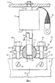
- Figure 1 of the drawings shows part of a typical electrical installation consisting of a fixed conductor rail 10, a movable actuator bar 11, and an electrical device 12 such as a vacuum circuit breaker.
- a shiftable plunger element 13 of the circuit breaker is fixedly secured to the actuator bar 11, and the body 14 of the circuit breaker is secured to the conductor rail 10 by means of the coupling device indicated generally by reference numeral 15.
- the principal conducting path controlled by the circuit breaker includes a braided connector 16 and the coupling device 15 so that the latter is required to establish a good electrical connection as well as provide firm but adjustable mechanical support for the circuit breaker.
- the coupling device 15 as illustrated consists of an inner ball member 17 having a screw-threaded central bore 18 which receives a screw-threaded lower portion of a coupling rod 19, the upper end of which is connected to the body 14 of the circuit breaker by means of a lug thereon as shown.
- the ball member 17 is formed with a slot 20 extending generally radially from the bore 18, preferably, as shown, to the outside surface 17a of the ball member, thereby to permit clamping pressure applied externally to the ball member to effect clamping of the ball member onto the coupling rod in the bore 18.
- the coupling device 15 further consists of an outer member constituted by two clamping elements in the form of plates 21 and 22, the latter having a transverse flange 23 which is drilled to accommodate mounting screws 24 for securing the coupling device 15 to the conductor rail 10.
- Each of the clamp plates 21 and 22 is formed or provided with a part-spherical recess, 25 and 26 respectively, the inner surfaces of which constitute clamping surfaces complementary with the external surface of the ball member 17.
- the clamp plate 21 is drilled at 27 to receive fastening bolts 28 which engage tapped holes 29 in the clamp plate 22 so that the clamp plates can be drawn towards one another to lock the ball member 17 and the coupling rod 19 together in one simple operation.
- the recesses 25 and 26 are so dimensioned and shaped that when the clamp plates 21 and 22 are assembled with the ball member 17, the plates cannot be brought into direct face-to-face engagement by operation of the bolts 28. This ensures that the plates must grip the ball member and apply a clamping force which on the one hand maintains the plates, and the rail 10 by which they are carried, in an adjustable orientation relative to the axis of the rod, and on the other hand causes the ball member itself to be clamped to the rod 19 at an adjustable axial position.
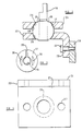
- the coupling device is denoted generally by reference numeral 15a and comprises an outer member constituted by two clamp plates 31 and 32, the latter having a flange 33 for the purpose described above in connection with the flange 23 shown in Figures 1 to 4.
- the clamp plates 31 and 32 have part-spherical recesses 35 and 36 constituting clamping surfaces, again similar to the arrangement described with reference to Figures 1 to 4, except that they are presented towards the axis of the rod 19, rather than longitudinally thereof.
- the clamp plate 31 is formed with bores 37 on either side of the axis of the coupling rod 19 to receive fastening bolts 38 which are engageable in tapped holes 39 in the clamp plate 32 so as to be operable to draw the clamp plates 31 and 32 together and thereby clamp the ball member 17.
- the modified coupling 15a further incorporates locating means associated with the clamp plates for keeping the latter in close mutual registration during operation of the fastening bolts 38.
- each fastening bolt 38 has a plain shank portion 40 which is received in close fitting engagement in the bore 37 in the clamp plate 31 and in a counter bore 41 in clamp plate 32.
- the shank 40, the bore 37, and the counter bore 41 effectively keep the clamp plate 31 in close registration with the clamp plate 32 even when the clamp bolts 38 are slackened sufficiently to permit rotational adjustment of the ball member 17, and the axial play permitted in the position of the ball member 17 is thus significantly less than compared with the arrangement shown in Figures 1 to 4.
- the recesses 35 and 36 are so dimensioned and shaped that the clamp plates 31 and 32 cannot be brought into direct face-to-face engagement with each other.
- locating means separate from and additional to the clamping bolts may alternatively be employed.
- a modified locating means may consist of a locating slide extending transversely from one clamp plate and engaging in parallel guides afforded by the other clamp plate.
- the ball member 19 is shown with a slot 20 which extends completely to the exterior surface thereof, in some circumstances the slot may extend only part-way from the ball to the exterior surface. Further, it would be possible for the slot 20 to extend across the whole diameter of the ball member so that the latter is of split construction and the two parts are held together by the associated clamp plates. Again, whilst it is preferred that both the inner and outer coupling members afford part-spherical clamping surfaces, it will be appreciated that one of such surfaces could be of some other shape, for example frusto-conical.
- clamping surfaces are of part-spherical shape so as to facilitate universal adjustment about a centre of rotation, it would be possible where so required in any particular application to utilise clamping surfaces of cylindrical or part-cylindrical shape so as to provide adjustment about a single axis of rotation which may or may not be substantially coincident with the axis of the rod.
- the coupling device since the coupling device is intended to form part of an electrically conductive path, the inner and outer members thereof will be preferably made of a good electrical conductor such as copper.
Landscapes
- Pivots And Pivotal Connections (AREA)
- Particle Accelerators (AREA)
- Breakers (AREA)
Claims (5)
Priority Applications (1)
| Application Number | Priority Date | Filing Date | Title |
|---|---|---|---|
| AT83107650T ATE25172T1 (de) | 1982-08-26 | 1983-08-03 | Kupplungsvorrichtung. |
Applications Claiming Priority (4)
| Application Number | Priority Date | Filing Date | Title |
|---|---|---|---|
| GB8224586 | 1982-08-26 | ||
| GB8224586 | 1982-08-26 | ||
| GB8230568 | 1982-10-26 | ||
| GB8230568 | 1982-10-26 |
Publications (2)
| Publication Number | Publication Date |
|---|---|
| EP0103721A1 EP0103721A1 (de) | 1984-03-28 |
| EP0103721B1 true EP0103721B1 (de) | 1987-01-21 |
Family
ID=26283679
Family Applications (1)
| Application Number | Title | Priority Date | Filing Date |
|---|---|---|---|
| EP83107650A Expired EP0103721B1 (de) | 1982-08-26 | 1983-08-03 | Kupplungsvorrichtung |
Country Status (6)
| Country | Link |
|---|---|
| US (1) | US4516814A (de) |
| EP (1) | EP0103721B1 (de) |
| AU (1) | AU564376B2 (de) |
| CA (1) | CA1217831A (de) |
| DE (1) | DE3369437D1 (de) |
| GB (1) | GB2126020B (de) |
Families Citing this family (9)
| Publication number | Priority date | Publication date | Assignee | Title |
|---|---|---|---|---|
| SE463325B (sv) * | 1988-11-14 | 1990-11-05 | Monsun Tison Ab | Anordning foer linjaerroerelse |
| US7081602B1 (en) | 2000-02-01 | 2006-07-25 | Trebor International, Inc. | Fail-safe, resistive-film, immersion heater |
| US6580061B2 (en) | 2000-02-01 | 2003-06-17 | Trebor International Inc | Durable, non-reactive, resistive-film heater |
| US6674053B2 (en) | 2001-06-14 | 2004-01-06 | Trebor International | Electrical, thin film termination |
| US6433319B1 (en) | 2000-12-15 | 2002-08-13 | Brian A. Bullock | Electrical, thin film termination |
| US6544583B2 (en) | 2000-02-01 | 2003-04-08 | Trebor International, Inc. | Method for adjusting resistivity of a film heater |
| US6663914B2 (en) | 2000-02-01 | 2003-12-16 | Trebor International | Method for adhering a resistive coating to a substrate |
| EP1164614A3 (de) * | 2000-06-14 | 2003-12-10 | Moeller GmbH | Rückseitiges Anschlusssystem für Niederspannungs-Leistungsschalter |
| US20080169647A1 (en) * | 2007-01-16 | 2008-07-17 | William James Kumpf | Hermetic refrigerant fitting |
Family Cites Families (14)
| Publication number | Priority date | Publication date | Assignee | Title |
|---|---|---|---|---|
| US348708A (en) * | 1886-09-07 | John p | ||
| CA653716A (en) * | 1962-12-11 | John Inglis Co. Limited | Current carrying joint | |
| GB330247A (en) * | 1929-03-02 | 1930-06-02 | Peerless Trading Company Spare | Pipe joint |
| GB484838A (en) * | 1937-02-12 | 1938-05-11 | Tubes Ltd | Improvements relating to ball and socket pipe couplings |
| US2667578A (en) * | 1950-01-31 | 1954-01-26 | Hughes Tool Co | Swivel joint for coaxial transmission lines |
| GB742693A (en) * | 1953-10-23 | 1955-12-30 | Victor Charles Gorman | Improvements in oil and grease nipple units for machinery |
| CH449350A (de) * | 1966-03-23 | 1967-12-31 | Mancar Trust | Rohrkupplung |
| DE2258355A1 (de) * | 1972-11-29 | 1974-05-30 | Hoechst Ag | Wartungsfreie gelenklager mit einem aussenmantel aus thermoplastischem kunststoff und verfahren zu ihrer herstellung |
| DE2331581C3 (de) * | 1973-06-20 | 1979-01-18 | Franz Wirschitz Gmbh Herstellung Von Freileitungs- Und Schaltanlagenarmaturen, 8000 Muenchen | Elektrische Klemme für Rohrleiter |
| FR2252672A1 (en) * | 1973-11-22 | 1975-06-20 | Alsthom Cgee | Connection of contactor and switch elements - involves ball and socket connection points which lowers overall contactor geometry |
| US3931992A (en) * | 1973-11-30 | 1976-01-13 | Badger Meter, Inc. | Universal joint connector |
| US4059360A (en) * | 1976-07-26 | 1977-11-22 | Etat Francais Represente Par De Delegue Ministeriel Pour L'armement | Device for mechanical connection |
| US4140413A (en) * | 1977-05-27 | 1979-02-20 | Dynaloc Corporation | Hub-locking device |
| FR2420685A1 (fr) * | 1978-03-22 | 1979-10-19 | Lemfoerder Metallwaren Ag | Articulation a rotule, en particulier articulation porteuse pour suspension de roues avant de vehicules automobiles |
-
1983
- 1983-08-02 AU AU17504/83A patent/AU564376B2/en not_active Expired - Fee Related
- 1983-08-03 DE DE8383107650T patent/DE3369437D1/de not_active Expired
- 1983-08-03 EP EP83107650A patent/EP0103721B1/de not_active Expired
- 1983-08-08 US US06/521,426 patent/US4516814A/en not_active Expired - Fee Related
- 1983-08-15 GB GB08321897A patent/GB2126020B/en not_active Expired
- 1983-08-26 CA CA000435435A patent/CA1217831A/en not_active Expired
Also Published As
| Publication number | Publication date |
|---|---|
| GB2126020B (en) | 1985-11-27 |
| AU564376B2 (en) | 1987-08-13 |
| GB2126020A (en) | 1984-03-14 |
| AU1750483A (en) | 1984-03-01 |
| CA1217831A (en) | 1987-02-10 |
| EP0103721A1 (de) | 1984-03-28 |
| US4516814A (en) | 1985-05-14 |
| DE3369437D1 (en) | 1987-02-26 |
| GB8321897D0 (en) | 1983-09-14 |
Similar Documents
| Publication | Publication Date | Title |
|---|---|---|
| EP0103721B1 (de) | Kupplungsvorrichtung | |
| US6171039B1 (en) | Locking mechanism for connector | |
| US20040005823A1 (en) | High capacity electrical terminal connection | |
| CN111313347B (zh) | 一种分裂导线间隔棒 | |
| US20010034153A1 (en) | Connector | |
| JPH07135051A (ja) | コネクタ取付機構 | |
| EP1276199A1 (de) | Freiverstellbare Klemme für Rohrsammelschienen und dgl. | |
| WO2022111607A1 (zh) | 一种开关柜用可旋转的母线支撑结构 | |
| CN212849570U (zh) | 引线绝缘固定杆 | |
| EP0525404B1 (de) | Elektrodenfassung von Elektrodentragarmen mit Kontaktbacke | |
| US20250343402A1 (en) | In-line connection assembly | |
| KR200179977Y1 (ko) | 케이블 고정장치 | |
| US2438233A (en) | Conductor grip for insulators | |
| US4379945A (en) | Adjustable insulator attachment for isolated phase bus switch | |
| JP3773974B2 (ja) | 母線の可変継手 | |
| CN117424009B (zh) | 一种用于电力系统的非标准电力金具 | |
| CN221552767U (zh) | 一种电力工程接线防护装置 | |
| CN217562488U (zh) | 支撑结构、断路器和gis设备 | |
| WO2002101896A3 (de) | Sammelschienenverbinder | |
| CN220325244U (zh) | 一种自锁式馈线卡具 | |
| EP4604326A1 (de) | Schnittstellenstecker für elektrische verbinder | |
| JPH073798B2 (ja) | 回転電力伝達装置 | |
| FI93596C (fi) | Päällystetyn avojohdon tiivis pääte | |
| JPH0635603Y2 (ja) | ケ−ブルヘツド保持装置 | |
| CS249832B1 (cs) | Spojka elektrických vodičů |
Legal Events
| Date | Code | Title | Description |
|---|---|---|---|
| PUAI | Public reference made under article 153(3) epc to a published international application that has entered the european phase |
Free format text: ORIGINAL CODE: 0009012 |
|
| AK | Designated contracting states |
Designated state(s): AT BE CH DE FR GB IT LI LU NL SE |
|
| 17P | Request for examination filed |
Effective date: 19840926 |
|
| RBV | Designated contracting states (corrected) |
Designated state(s): AT BE CH DE FR IT LI LU NL SE |
|
| RAP1 | Party data changed (applicant data changed or rights of an application transferred) |
Owner name: SIMPLEX ELECTRICAL LIMITED |
|
| GRAA | (expected) grant |
Free format text: ORIGINAL CODE: 0009210 |
|
| AK | Designated contracting states |
Kind code of ref document: B1 Designated state(s): AT BE CH DE FR IT LI LU NL SE |
|
| PG25 | Lapsed in a contracting state [announced via postgrant information from national office to epo] |
Ref country code: NL Effective date: 19870121 Ref country code: LI Effective date: 19870121 Ref country code: IT Free format text: LAPSE BECAUSE OF FAILURE TO SUBMIT A TRANSLATION OF THE DESCRIPTION OR TO PAY THE FEE WITHIN THE PRESCRIBED TIME-LIMIT;WARNING: LAPSES OF ITALIAN PATENTS WITH EFFECTIVE DATE BEFORE 2007 MAY HAVE OCCURRED AT ANY TIME BEFORE 2007. THE CORRECT EFFECTIVE DATE MAY BE DIFFERENT FROM THE ONE RECORDED. Effective date: 19870121 Ref country code: CH Effective date: 19870121 Ref country code: AT Effective date: 19870121 |
|
| REF | Corresponds to: |
Ref document number: 25172 Country of ref document: AT Date of ref document: 19870215 Kind code of ref document: T |
|
| PG25 | Lapsed in a contracting state [announced via postgrant information from national office to epo] |
Ref country code: SE Effective date: 19870131 |
|
| REF | Corresponds to: |
Ref document number: 3369437 Country of ref document: DE Date of ref document: 19870226 |
|
| ET | Fr: translation filed | ||
| REG | Reference to a national code |
Ref country code: CH Ref legal event code: PL |
|
| NLV1 | Nl: lapsed or annulled due to failure to fulfill the requirements of art. 29p and 29m of the patents act | ||
| PG25 | Lapsed in a contracting state [announced via postgrant information from national office to epo] |
Ref country code: LU Free format text: LAPSE BECAUSE OF NON-PAYMENT OF DUE FEES Effective date: 19870831 |
|
| PLBE | No opposition filed within time limit |
Free format text: ORIGINAL CODE: 0009261 |
|
| STAA | Information on the status of an ep patent application or granted ep patent |
Free format text: STATUS: NO OPPOSITION FILED WITHIN TIME LIMIT |
|
| 26N | No opposition filed | ||
| PGFP | Annual fee paid to national office [announced via postgrant information from national office to epo] |
Ref country code: FR Payment date: 19900807 Year of fee payment: 8 |
|
| PGFP | Annual fee paid to national office [announced via postgrant information from national office to epo] |
Ref country code: LU Payment date: 19900823 Year of fee payment: 8 |
|
| PGFP | Annual fee paid to national office [announced via postgrant information from national office to epo] |
Ref country code: BE Payment date: 19900904 Year of fee payment: 8 |
|
| PGFP | Annual fee paid to national office [announced via postgrant information from national office to epo] |
Ref country code: DE Payment date: 19900927 Year of fee payment: 8 |
|
| PG25 | Lapsed in a contracting state [announced via postgrant information from national office to epo] |
Ref country code: BE Effective date: 19910831 |
|
| BERE | Be: lapsed |
Owner name: SIMPLEX ELECTRICAL LTD Effective date: 19910831 |
|
| PG25 | Lapsed in a contracting state [announced via postgrant information from national office to epo] |
Ref country code: FR Effective date: 19920430 |
|
| PG25 | Lapsed in a contracting state [announced via postgrant information from national office to epo] |
Ref country code: DE Effective date: 19920501 |
|
| REG | Reference to a national code |
Ref country code: FR Ref legal event code: ST |