EP0103548A2 - Leichter Lötkolben besonders geeignet für Weich- und Silberlöten und ähnliches - Google Patents
Leichter Lötkolben besonders geeignet für Weich- und Silberlöten und ähnliches Download PDFInfo
- Publication number
- EP0103548A2 EP0103548A2 EP83830166A EP83830166A EP0103548A2 EP 0103548 A2 EP0103548 A2 EP 0103548A2 EP 83830166 A EP83830166 A EP 83830166A EP 83830166 A EP83830166 A EP 83830166A EP 0103548 A2 EP0103548 A2 EP 0103548A2
- Authority
- EP
- European Patent Office
- Prior art keywords
- circuit
- capacitor
- reaction
- welder
- diode
- Prior art date
- Legal status (The legal status is an assumption and is not a legal conclusion. Google has not performed a legal analysis and makes no representation as to the accuracy of the status listed.)
- Granted
Links
Images
Classifications
-
- B—PERFORMING OPERATIONS; TRANSPORTING
- B23—MACHINE TOOLS; METAL-WORKING NOT OTHERWISE PROVIDED FOR
- B23K—SOLDERING OR UNSOLDERING; WELDING; CLADDING OR PLATING BY SOLDERING OR WELDING; CUTTING BY APPLYING HEAT LOCALLY, e.g. FLAME CUTTING; WORKING BY LASER BEAM
- B23K3/00—Tools, devices or special appurtenances for soldering, e.g. brazing, or unsoldering, not specially adapted for particular methods
- B23K3/02—Soldering irons; Bits
- B23K3/03—Soldering irons; Bits electrically heated
- B23K3/033—Soldering irons; Bits electrically heated comprising means for controlling or selecting the temperature or power
Definitions
- This invention refers to a light-weight welder particularly suitable for soft and silver soldering and the like, the power of which is variable according to the welding temperature, wherein the welding tip is the sensing member for detecting the welding temperature. Furthermore, the welder of the invention has an extremely low thermic inertia whcreby the power delivered immediately reaches the value of the power required.
- the welders available at present to carry out a welding of this type are essentially of three dif- ierent types.
- Trigger-operated rapid or pistol welders which are mainly used for soft soldering, have a welding tip which reaches almost immediately the operating temperature corresponding to the solder melting temperature.
- the above-mentioned welders comprise a network voltage transformer having the secondary on the welding tip.
- Welders of the second type are welders comprising a continously loaded resistor.
- Welders of the third type are essentially welders of the second type provided with a thermostat which controls the power supplied to the resistor, cutting off this power supply whenever the welding tip reaches an excessive temperature.
- Welders of the first type or rapid welders operate at extremely variable welding temperatures and at constant power. Accordingly, the welding tip can reach temperatures much higher than the solder melting temperature and thus the welding tip is "burnt". Furthermore, the solder can also "bind" to the tip, thus preventing any further use thereof.
- Welders of the second type wherein the temperature is controlled by dissipating heat into the environment, have a drawback in that these welders very easily reach temperatures at which the solder burns, thus causing the solder to "bind" to the welding tip.
- Welders of the third type have a theorical advantage in that the welding temperature is kept constant by the thermostat, but they have high thermic inertia. Accordingly, the thermostatic control of the tip occurs with a considerable delay and thus the inherent advantages of the above-mentioned structure are almost completely cancelled.
- the use of the welders available at present is the source of many drawbacks the most serious of which, from an economic point of view, being that the excessively high tip temperature not only causes the solder to burn, but can also damage the costly electronic components to be welded.
- welders should thus be used in manufacturing electronic circuits with some precautions which highly increase the manufacturing time.
- the welder of the invention comprises a tip temperature control circuit automatically controlling the power supplied. Accordingly, the welding temperature is always comprised between the optimal range, thus allowing a "not burnt” welding to be obtained and preventing the electronic components from being damaged when these electronic components must be welded to printed circuits or the like.
- the welder of the invention which is similar to the welders provided with a thermostat but is free from the drawbacks thereof, is characterized in that the welding tip is the temperature detecting member which is connected to the temperature control circuit which thus controls the power supplied. Accordingly, the variation of the power supply required for keeping the welding tip temperature at a constant level occurs practically immediately.
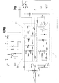
- the welder of the invention essentially comprises: a network voltage transformer TRF having a primary B and four secondaries BP, Bl, B2 and B3; an excitation circuit CQ; a first reaction circuit CR1: a second reaction circuit CR2; a welding tip PS and a protection circuit CIRP (Fig. 1).
- the circuit of Figure 1 comprises two diodes Dl, D2, a lamp LI for lighting the working area and an input circuit CA connected thereto, a thermistor RQ of the NTC type for protecting the diodes of bridge PR and an operating push button PA.
- Excitation circuit CQ comprises a resistor RQ1, a resistor RQ2, a capacitor CQ1 and a low vacuum luminous tube TLBV.
- First reaction circuit CR1 comprises secondary Bl of transformer TRF, a first capacitor CPR1, a second capacitor CGR1, a diode DR1, a rheostat RS1 for controlling the temperature of welding tip PT and a transistor TR1.
- Second reaction circuit CR2 comprises secondary B2 of transformer TRF, a first capacitor CPR2, a second capacitor CCR2, a diode DR2 and a transistor TR2.
- Protection circuit CIRP comprises a diode D3, a diode D4, a thermistor THR and a transistor TR3.
- welding tip PT is connected to secondary BP of transformer TRF, while reaction circuits CR1 and CR2 are connected to secondaries Bl and B2 respectively, and the working area lighting lamp LI is connected to secondary B3 of transformer TRF.
- bridge PR The output of bridge PR is connected to capacitor Cl, which is preferably of the electrolytic type, and is the welder input.
- Diodes Dl and D2 on the network voltage reveal the 100 Hz pulses, namely twice the network fre- cuency, and supply excitation circuit CQ.
- Capacitor CQ1 is loaded by diodes Dl, D2, partially equalizes the pulsing voltage and unloads on the base of transistor TR2 of second reaction circuit CR2.
- Reaction circuits CR1 and CR2 comprise combinations of capacitors and resistors causing the phase to rotate from the output of TR1 and TR2 and the reaction on the base thereof, thus obtaining an optimal reaction on the base of TR1.
- first reaction circuit CR1 comprises a rheostat RS1 in series with the base of TR1, which rheostat RS1 controls the value of the temperature of welding tip PT.
- Diode DR1 of circuit CR1 and diode DR2 of circuit CR2 act as peak detectors and load capacitor CC1 and the like with a negative voltage.
- transistors TR1, TR2 are normally inhibited but each time that TLBV de-energizes transistor TR2 turns ON whereby primary B of transformer TRF receives power and a reaction signal is developped on secondaries Bl and B2 thereof.
- This reaction signal supplies a voltage alternatively to the bases of TR1 and TR2 which thus aelf-oscillate while diodes DRl and DR2 connected to the bases of transistors TRl, TR2 tend to inhibit these transistors.
- the new concept of the welder of the invention is to use the property of conductive metals according to which the ohmic resistance thereof increases according to the increase in temperature.
- the increase in the ohmic resistance of the welding tip PT due to the increase in the temperature thereof causes a variation of the load on primary B of transformer TRF. Accordingly there is a variation of the inductance of transformer TRF which is connected to capacitor CP, since the circuit is self-oscillating, and a variation of the voltage on the terminals of primary B.
- This variation of the voltage on primary B and the variation of the voltage on secondaries Bl and B2 together with the variation of the oscillation frequency of transistors TR1 and TR2 affect both the base voltage of these transistors and the reaction signal phase thus causing a rotation of the phase and a modification of the amplitude.
- transistors TR1 and TR2 act as a blocked oscillator at the maximum value of the temperature of tip PT and as a continuous oscillator at the minimum value of such temperature.
- low vacuum tube TLBV is intended to trigger reaction circuit CR2 whenever the oscillation thereof is blocked.
- Figure 1 shows a protection circuit for protecting the welder against the overheating of transistors TR1 and TR2 or transformer TRF.
- protection circuit CIRCP is connected to the welder circuit at common points a, b, c and d.
- thermistor THR which operates as a grounded divider and is located close to the dissipator of transistors TR1 and TR2 heats as the temperature of the dissipator increases, thus causing a decrease in the ohmic resistance thereof.
- the working area lighting lamp LI is supplied by circuit CA which comprises secondary B3 of transformer TRF and rectifier RRR.
Landscapes
- Engineering & Computer Science (AREA)
- Mechanical Engineering (AREA)
- Arc Welding Control (AREA)
- Adhesives Or Adhesive Processes (AREA)
- Ceramic Products (AREA)
- Arc Welding In General (AREA)
- Nonmetallic Welding Materials (AREA)
- General Induction Heating (AREA)
Applications Claiming Priority (2)
| Application Number | Priority Date | Filing Date | Title |
|---|---|---|---|
| IT8249004A IT1212548B (it) | 1982-08-18 | 1982-08-18 | Saldatore leggero, specialmente adatto per saldature a stagno argento e simili |
| IT4900482 | 1982-08-18 |
Publications (3)
| Publication Number | Publication Date |
|---|---|
| EP0103548A2 true EP0103548A2 (de) | 1984-03-21 |
| EP0103548A3 EP0103548A3 (en) | 1986-12-30 |
| EP0103548B1 EP0103548B1 (de) | 1994-06-01 |
Family
ID=11269354
Family Applications (1)
| Application Number | Title | Priority Date | Filing Date |
|---|---|---|---|
| EP83830166A Expired - Lifetime EP0103548B1 (de) | 1982-08-18 | 1983-08-16 | Leichter Lötkolben besonders geeignet für Weich- und Silberlöten und ähnliches |
Country Status (5)
| Country | Link |
|---|---|
| US (1) | US4766289A (de) |
| EP (1) | EP0103548B1 (de) |
| AT (1) | ATE106295T1 (de) |
| DE (1) | DE3382751D1 (de) |
| IT (1) | IT1212548B (de) |
Cited By (1)
| Publication number | Priority date | Publication date | Assignee | Title |
|---|---|---|---|---|
| EP0337065A1 (de) * | 1988-04-12 | 1989-10-18 | ERSA Ernst Sachs KG GmbH & Co. | Verfahren und Vorrichtung zum Betrieb einer Lötstation |
Families Citing this family (7)
| Publication number | Priority date | Publication date | Assignee | Title |
|---|---|---|---|---|
| IT1207334B (it) * | 1986-11-05 | 1989-05-17 | Santoro Giovanni Francolini Er | Saldatore leggero,specialmente adatto per saldature a stagno argento esimili |
| JPH01254381A (ja) * | 1988-04-02 | 1989-10-11 | Hakko Kinzoku Kogyo Kk | 半田こての温度調整装置 |
| DE9216992U1 (de) * | 1992-12-14 | 1993-03-11 | Biro, Laszlo, Nyiregyaza | Elektrische Lötvorrichtung |
| US6093915A (en) * | 1999-02-19 | 2000-07-25 | Cooper Industries, Inc. | Magnet and reed switch/lock |
| CA2358602A1 (en) * | 2001-10-09 | 2003-04-09 | Norax Canada Inc. | Resonance controlled conductive heating |
| CN109226925B (zh) * | 2018-08-16 | 2024-10-01 | 佛山勤顺科技有限公司 | 一种轻巧型速热电烙铁 |
| CN109014482A (zh) * | 2018-09-27 | 2018-12-18 | 佛山勤顺科技有限公司 | 自带发热体的电烙铁头及其应用 |
Family Cites Families (13)
| Publication number | Priority date | Publication date | Assignee | Title |
|---|---|---|---|---|
| US915974A (en) * | 1906-01-05 | 1909-03-23 | Harry Ward Leonard | Automatic thermo-electric control. |
| GB892825A (en) * | 1959-01-15 | 1962-03-28 | Plessey Co Ltd | Improvements in or relating to electric control circuits |
| US2969449A (en) * | 1959-08-25 | 1961-01-24 | Jonathan E Tyler | Resistance soldering power supply |
| FR2141245A5 (de) * | 1972-06-06 | 1973-01-19 | Courdavault Rene | |
| US4115676A (en) * | 1976-02-10 | 1978-09-19 | Tokyo Shibaura Electric Co., Ltd. | Induction heating apparatus |
| US4114010A (en) * | 1976-03-22 | 1978-09-12 | Park-Ohio Industries, Inc. | Test circuit and method for matching an induction load to a solid state power supply |
| JPS52147729A (en) * | 1976-06-04 | 1977-12-08 | Matsushita Electric Ind Co Ltd | Frequency converter |
| DE2809089A1 (de) * | 1978-03-02 | 1979-09-13 | Cooper Ind Inc | Loetwerkzeug mit temperaturregelung |
| JPS5922966B2 (ja) * | 1978-09-26 | 1984-05-30 | 日本電気三栄株式会社 | 温度制御装置とこれを用いた記録ペン |
| DE3023909A1 (de) * | 1980-06-26 | 1982-08-19 | Wilhelm Bosbach Gmbh & Co Kg, 5630 Remscheid | Elektrische loetpistole |
| DE3115569A1 (de) * | 1981-04-16 | 1982-12-09 | Cooper Industries, Inc., 77210 Houston, Tex. | "elektrisch beheiztes loetwerkzeug" |
| GB2122058B (en) * | 1982-05-28 | 1985-10-23 | Glaverbel | Method and apparatus for bonding glazing panels |
| JPS59103292A (ja) * | 1982-12-03 | 1984-06-14 | 三洋電機株式会社 | 誘導加熱調理器 |
-
1982
- 1982-08-18 IT IT8249004A patent/IT1212548B/it active
-
1983
- 1983-08-16 DE DE3382751T patent/DE3382751D1/de not_active Expired - Lifetime
- 1983-08-16 AT AT83830166T patent/ATE106295T1/de not_active IP Right Cessation
- 1983-08-16 EP EP83830166A patent/EP0103548B1/de not_active Expired - Lifetime
-
1986
- 1986-06-23 US US06/877,386 patent/US4766289A/en not_active Expired - Fee Related
Cited By (1)
| Publication number | Priority date | Publication date | Assignee | Title |
|---|---|---|---|---|
| EP0337065A1 (de) * | 1988-04-12 | 1989-10-18 | ERSA Ernst Sachs KG GmbH & Co. | Verfahren und Vorrichtung zum Betrieb einer Lötstation |
Also Published As
| Publication number | Publication date |
|---|---|
| IT8249004A0 (it) | 1982-08-18 |
| US4766289A (en) | 1988-08-23 |
| IT1212548B (it) | 1989-11-30 |
| DE3382751D1 (de) | 1994-07-07 |
| ATE106295T1 (de) | 1994-06-15 |
| EP0103548B1 (de) | 1994-06-01 |
| EP0103548A3 (en) | 1986-12-30 |
Similar Documents
| Publication | Publication Date | Title |
|---|---|---|
| US4259614A (en) | Electronic ballast-inverter for multiple fluorescent lamps | |
| EP0103548A2 (de) | Leichter Lötkolben besonders geeignet für Weich- und Silberlöten und ähnliches | |
| US4005335A (en) | High frequency power source for fluorescent lamps and the like | |
| EP1135974B1 (de) | Elektronischer trafo für die beleuchtung | |
| US5023516A (en) | Discharge lamp operation apparatus | |
| US4045711A (en) | Tuned oscillator ballast circuit | |
| US4527099A (en) | Control circuit for gas discharge lamps | |
| US5021634A (en) | Temperature controlled soldering iron employing a variable resistance heating element for temperature sensing | |
| JPH0241662A (ja) | 電源装置 | |
| EP0041589A1 (de) | Elektronischer Ballast für Fluoreszenzröhren | |
| US4638226A (en) | Speed control system with feedback and soft-start | |
| US5059766A (en) | Method and apparatus for improved arc striking | |
| US5370664A (en) | Pulse forming circuits | |
| JPS59158415A (ja) | 加熱素子の熱効率調整回路 | |
| US5045670A (en) | Method and apparatus for extending the brush life of a cooling fan in an electronic welder | |
| JP2010162672A (ja) | 電動工具 | |
| US5017756A (en) | Method and apparatus for preventing chain reaction transistor failure in paralleled transistors | |
| US7372210B2 (en) | Method and apparatus for lamp heat control | |
| US5264988A (en) | Circuit to limit surges into a dc-operated lamp | |
| JP2672981B2 (ja) | 充電・交流両用電動工具の電源回路 | |
| US4031349A (en) | Stud welding control | |
| EP0254506B1 (de) | Schaltung zur Begrenzung von Überspannungen in gleichstrombetriebenen Lampen | |
| JPS5926793Y2 (ja) | 大電力トランジスタを用いたチョッパ装置 | |
| JPH0333070B2 (de) | ||
| JP3187477B2 (ja) | スイッチング電源装置及びそれに用いる複合素子 |
Legal Events
| Date | Code | Title | Description |
|---|---|---|---|
| PUAI | Public reference made under article 153(3) epc to a published international application that has entered the european phase |
Free format text: ORIGINAL CODE: 0009012 |
|
| AK | Designated contracting states |
Designated state(s): AT BE CH DE FR GB LI NL SE |
|
| 17P | Request for examination filed |
Effective date: 19841024 |
|
| PUAL | Search report despatched |
Free format text: ORIGINAL CODE: 0009013 |
|
| AK | Designated contracting states |
Kind code of ref document: A3 Designated state(s): AT BE CH DE FR GB LI NL SE |
|
| 17Q | First examination report despatched |
Effective date: 19880615 |
|
| GRAA | (expected) grant |
Free format text: ORIGINAL CODE: 0009210 |
|
| AK | Designated contracting states |
Kind code of ref document: B1 Designated state(s): AT BE CH DE FR GB LI NL SE |
|
| PG25 | Lapsed in a contracting state [announced via postgrant information from national office to epo] |
Ref country code: NL Effective date: 19940601 Ref country code: LI Effective date: 19940601 Ref country code: FR Effective date: 19940601 Ref country code: CH Effective date: 19940601 Ref country code: BE Effective date: 19940601 Ref country code: AT Effective date: 19940601 |
|
| REF | Corresponds to: |
Ref document number: 106295 Country of ref document: AT Date of ref document: 19940615 Kind code of ref document: T |
|
| REF | Corresponds to: |
Ref document number: 3382751 Country of ref document: DE Date of ref document: 19940707 |
|
| PG25 | Lapsed in a contracting state [announced via postgrant information from national office to epo] |
Ref country code: SE Effective date: 19940901 Ref country code: GB Effective date: 19940901 |
|
| PG25 | Lapsed in a contracting state [announced via postgrant information from national office to epo] |
Ref country code: DE Effective date: 19940902 |
|
| REG | Reference to a national code |
Ref country code: CH Ref legal event code: PL |
|
| EN | Fr: translation not filed | ||
| NLV1 | Nl: lapsed or annulled due to failure to fulfill the requirements of art. 29p and 29m of the patents act | ||
| PLBE | No opposition filed within time limit |
Free format text: ORIGINAL CODE: 0009261 |
|
| STAA | Information on the status of an ep patent application or granted ep patent |
Free format text: STATUS: NO OPPOSITION FILED WITHIN TIME LIMIT |
|
| GBPC | Gb: european patent ceased through non-payment of renewal fee |
Effective date: 19940901 |
|
| 26N | No opposition filed |