EP0103423B1 - Anlage zum Brennen von pulverförmigem Rohmaterial - Google Patents
Anlage zum Brennen von pulverförmigem Rohmaterial Download PDFInfo
- Publication number
- EP0103423B1 EP0103423B1 EP83304758A EP83304758A EP0103423B1 EP 0103423 B1 EP0103423 B1 EP 0103423B1 EP 83304758 A EP83304758 A EP 83304758A EP 83304758 A EP83304758 A EP 83304758A EP 0103423 B1 EP0103423 B1 EP 0103423B1
- Authority
- EP
- European Patent Office
- Prior art keywords
- kiln
- inlet
- suspension
- duct
- gas
- Prior art date
- Legal status (The legal status is an assumption and is not a legal conclusion. Google has not performed a legal analysis and makes no representation as to the accuracy of the status listed.)
- Expired
Links
Images


Classifications
-
- B—PERFORMING OPERATIONS; TRANSPORTING
- B01—PHYSICAL OR CHEMICAL PROCESSES OR APPARATUS IN GENERAL
- B01J—CHEMICAL OR PHYSICAL PROCESSES, e.g. CATALYSIS OR COLLOID CHEMISTRY; THEIR RELEVANT APPARATUS
- B01J6/00—Heat treatments such as Calcining; Fusing ; Pyrolysis
-
- C—CHEMISTRY; METALLURGY
- C04—CEMENTS; CONCRETE; ARTIFICIAL STONE; CERAMICS; REFRACTORIES
- C04B—LIME, MAGNESIA; SLAG; CEMENTS; COMPOSITIONS THEREOF, e.g. MORTARS, CONCRETE OR LIKE BUILDING MATERIALS; ARTIFICIAL STONE; CERAMICS; REFRACTORIES; TREATMENT OF NATURAL STONE
- C04B7/00—Hydraulic cements
- C04B7/36—Manufacture of hydraulic cements in general
- C04B7/43—Heat treatment, e.g. precalcining, burning, melting; Cooling
- C04B7/434—Preheating with addition of fuel, e.g. calcining
-
- F—MECHANICAL ENGINEERING; LIGHTING; HEATING; WEAPONS; BLASTING
- F27—FURNACES; KILNS; OVENS; RETORTS
- F27B—FURNACES, KILNS, OVENS OR RETORTS IN GENERAL; OPEN SINTERING OR LIKE APPARATUS
- F27B7/00—Rotary-drum furnaces, i.e. horizontal or slightly inclined
- F27B7/20—Details, accessories or equipment specially adapted for rotary-drum furnaces
- F27B7/2016—Arrangements of preheating devices for the charge
- F27B7/2025—Arrangements of preheating devices for the charge consisting of a single string of cyclones
- F27B7/2033—Arrangements of preheating devices for the charge consisting of a single string of cyclones with means for precalcining the raw material
Definitions
- the present invention concerns an apparatus for burning pulverulent raw material, the apparatus comprising a preheater, a suspension calciner assembly, a kiln, and an air cooler.
- the apparatus may be used e.g. in the production of cement, i.e. when the pulverulent raw material is cement raw meal, in particular Portland cement raw meal with an oxide analysis on an ignition free basis within the ranges CaO: 60-67% by weight, Si0 2 : 17-25% by weight, A1 2 0 3 : 3-8% by weight, Fe 2 0 3 : 0.5-6% by weight, MgO: 0.1-5.5% by weight, Na 2 0+K 2 0: 0.5-1.3% by weight and S0 3 : 1-3% by weight; or for converting complex aluminium silicates to dicalcium silicate and water soluble aluminates by the lime or the lime/soda process.
- cement raw meal in particular Portland cement raw meal with an oxide analysis on an ignition free basis within the ranges CaO: 60-67% by weight, Si0 2 : 17-25% by weight, A1 2 0 3 : 3-8% by weight, Fe 2 0 3 : 0.5-6% by weight, MgO: 0.1
- the apparatus is particularly suitable for burning cement raw meal, especially Portland cement raw meal to cement clinker by the dry process.
- phase (1) is performed in the suspension preheater, phase (3) in the rotary kiln and phase (2) partially in the suspension preheater and partially in the rotary kiln.
- suspension may indicate a two-phase system consisting of a finely divided solid dispersed in a solid, liquid or gas.
- the term “suspension” is intended to indicate a gas/particle suspension, i.e. a two-phase system consisting of a finely divided solid dispersed in, and entrained by, a stream of gas.
- the layouts may comprise two string preheaters with two parallel arrays of cyclones one with kiln exhaust gas as heating gas and the other with calciner exhaust gas as heating gas, known from GB-A-1,434,091, or one string preheaters with a mixture of kiln and calciner exhaust gas as heating gas.
- kiln gas and calciner gas may be mixed in the calciner or after the calciner gas has passed through the particle precipitator of the calciner.
- the mixing of kiln gas and calciner gas in the calciner is in most cases achieved by mixing kiln gas and hot air in or upstream of the burning chamber of the calciner or by operating the kiln with a considerable hot air surplus, i.e. providing a mixture of hot air and kiln gas in the kiln, and introducing this mixture into the burning chamber of the calciner.
- Such plants are for instance known from GB-A-1,428,828, 1,423,875, 1,489,416 and 1,406,965.
- pulverized coal with a content of volatile matter (determined according to ASTM Standard D3175) below 30%
- pulverized coal with a broad particle size distribution, and/or pulverized coal having a considerable amount of coarse particles may present difficulties due to lack of total burning out of, in particular, the coarse coal particles. This may show itself partly as undesirable burning in the particle precipitator and partly as undesirable occurrences of unburnt coal in the calcined product withdrawn from the particle precipitator.
- the calciner burning chamber is supplied with fuel and air. It has been found that it is possible to reduce the burning out time for natural gas, and even for difficult types of coal, compared to the burning out time in plants in which a mixture of hot air and kiln gas is introduced into the burning chamber of the calciner, presumably because of the higher oxygen concentration of the gas introduced into the burning chamber.
- the object of the invention is to overcome this problem and to provide an apparatus which can easily be constructed by rebuilding an existing plant, particularly a cement production plant, which has a multi-stage cyclone suspension preheater connected to a rotary kiln, but no separate calciner.
- an apparatus of the kind described is characterized in that the suspension transfer duct is connected to the sub-assembly of kiln gas duct and precipitator downstream of the material inlet of the kiln gas duct.
- the first stream of pulverulent raw material is suspended in the gas stream in the burning chamber, and calcined, if desired almost completely.
- the reaction velocity for the reaction between fuel and oxygen is sufficiently high to ensure complete burning out of gas and even of difficult types of coal.
- the second stream of pulverulent raw material is introduced into and suspended in the kiln gas leaving the kiln, upstream of where the hot material which has been treated in the burning chamber is introduced, providing a rapid quenching of the kiln gas. This is very important in reducing bakings in the upstream end of the kiln gas duct. Practically any desired degree of calcination of the second stream of pulverulent raw material i.e. any desired degree of calcination of the calcined product withdrawn from the particle precipitator, can be achieved, depending on the mass ratio between the first and the second streams of pulverulent raw material.
- the burning chamber of the calciner may be operated at temperatures normally maintained in suspension calciners, i.e. within the range 830-1050°C, preferentially 850-950°C, but if desired at temperatures which are 100-300°C higher than according to normal calcining conditions without meeting problems of overheating, hot spots, and bakings.
- the gas retention time in the burning chamber is typically within the range 0.5-5, preferentially 1-3 seconds.
- a typical degree of calcination of the first stream of material withdrawn in suspension from the burning chamber is 70-100%, preferentially 85-98%.
- a typical degree of calcination of the second stream of material calcined suspended in kiln gas is 50-100%, preferentially 60-90%.
- the temperature of the calciner exhaust gas withdrawn from the particle precipitator and introduced into the preheater is typically 850-950°C.
- the preheater is preferentially a multi-stage suspension preheater. In particular preheaters comprising three or four cyclone stages are preferred.
- the material is preheated to a temperature within the range 500-850°C, preferentially within the range 600-830°C.
- the kiln is preferentially a short rotary kiln i.e. one less than 50m long.
- liquid fuels such as fuel oil, gaseous fuels, such as natural gas, and solid fuels, such as pulverized coal.
- the dividing of the preheated pulverulent raw material into two streams may be provided by known methods, e.g. by means of dividing dampers or by dividing a suspension of the material into two streams and directing the two streams to separate precipitation cyclones in the preheater.
- a preferred mass ratio between the first and the second streams of pulverulent raw material is within the range 15-1.
- the apparatus allows an extremely simple up start.
- all material from the preheater is introduced into the kiln gas duct and neither fuel, nor material nor air is directed to the suspension burning chamber, i.e. at the beginning the apparatus is operated as a kiln with a preheater but no calciner.
- hot clinker arrives at the air cooler, and when the hot air from the cooler has obtained a temperature of about 700°C, the first stream of material from the preheater and fuel may gradually be directed to the suspension burning chamber.
- the suspension burning chamber is a tubular chamber having an upright axis, an annular bottom wall which slopes downwardly and inwardly, a central inlet for hot air in the bottom, the inlets for the fuel and raw material being arranged to discharge fuel and the first stream of raw material onto the bottom of the burning chamber, and a suspension outlet opening at the top of the burning chamber connected to the suspension transfer duct.
- the kiln gas duct may be provided with a tubular retention chamber having an upright axis, an annular bottom wall which slopes downwardly and inwardly, a central inlet for kiln gas in the bottom, and a suspension outlet opening at the top of the retention chamber connected to the particle precipitator; the material duct opening of the kiln gas duct being arranged between combustion gas inlet and the retention chamber or at the bottom of the retention chamber; and the suspension transfer duct being connected to the kiln gas duct between the combustion gas inlet and the retention chamber or at the bottom of the retention chamber.
- the suspension transfer duct preferentially leads tengentially into the bottom of the retention chamber, but it may also extend between the retention chamber and particle precipitator.
- the gas retention time in the retention chamber is typically 0.3-3 seconds.
- the kiln gas duct may be provided with a throttle in order to maintain a suitable division of hot air between kiln and calciner.
- the gas flow resistance of the throttle is made somewhat larger than that of a hot air pipe connecting the air cooler and the hot air inlet of the suspension burning chamber.
- the material inlet opening of the kiln gas duct may be arranged downstream, but in order to eliminate the risk for formation of bakings in the riser pipe preferentially upstream of the throttle.
- the mass ratio between the hot air streams directed to the suspension burning chamber and to the rotary kiln, respectively may be controlled by means of a valve arranged in the hot air pipe.
- the kiln gas duct may be provided with a supplementary fuel inlet, preferentially arranged close to the material inlet opening of the kiln gas duct.
- the supplementary fuel inlet may alternatively be arranged at the bottom of the retention chamber. A surplus of hot air is then drawn through the kiln and a large amount of preheated material may be calcined in the kiln gas duct by the heat produced by burning the supplementary fuel.
- the mass ratio between the first and the second stream of preheated pulverulent raw material is preferentially within the range 7-1.
- the mass ratio is preferentially 15 ⁇ 5.
- the invention also includes a method of converting a plant for burning pulverulent raw material, the plant being of the kind comprising a multi-stage cyclone preheater in which pulverulent cement raw material is preheated by exhaust gas from a kiln, and from the lowermost cyclone stage of which the material is fed to the kiln for burning and thereafter to an air cooler connected to the kiln for cooling of the burned material, the kiln exhaust gas passing from the kiln to the lowermost cyclone stage via a riser pipe to which the material is fed from the penultimate cyclone stage; the method comprising providing the plant with a calciner burning chamber having a fuel inlet, and an air inlet connected to the cooler so that waste cooling air is fed to the burning chamber; a suspension transfer duct leading from the burning chamber to the riser pipe downstream of the material feed to the riser pipe, or to the lowermost cyclone stage; and means for dividing the material leaving the penultimate cyclone stage and for feeding
- the plant has a rotary kiln 1 provided with a burner which is not shown and connected to an air cooler 2.
- the kiln has an upper end 13 forming a material inlet and a kiln exhaust gas outlet, and a lower end 35 providing both an inlet for fuel and hot air and an outlet for burned material.
- the burned material outlet 35 of the kiln is connected to a material inlet 36 of the cooler which has an outlet 38 for the material after cooling.
- the cooler 2 has an inlet 37 for cooling air and two waste hot air outlets 39 and 40 which are connected to the kiln hot air inlet 35 and to a pipe 3, respectively.
- the pipe 3 leads part of the cooler exit air to a calciner assembly comprising a suspension burning chamber 4 with inlets for fuel 5, a first stream of pulverulent raw material 6, and hot air 7 and provided with a suspension outlet transfer duct 8 connected directly or indirectly to a particle precipitator cyclone 9.
- the cyclone 9 has a calciner exhaust gas outlet 10 and an outlet duct 11 for calcined material leading the calcined material to the material inlet 13 of the rotary kiln 1.
- the calciner assembly is further provided with a kiln gas duct 28 leading to a suspension inlet 47 of the cyclone 9 and having a combustion gas inlet 33 connected to the kiln exhaust gas outlet 13, and an inlet opening 12 for a second stream of pulverulent raw material.
- the calciner exhaust gas outlet 10 provides preheating gas to a multi-stage cyclone preheater comprising riser pipes 14, 15, J6, and 17 leading to cyclones 18, 18', :19, 20 and 21, respectively, which are provided with material outlet ducts 22, 22' (or 22"), 23, 24, and 25, respectively.
- the preheating gas is provided by exhaust gas from the burning chamber 4, and from the kiln 1 via the kiln gas duct 28.
- the multi-stage cyclone preheater is further provided with a material inlet duct 26 and an exit gas outlet 27 provided with a filter and ventilator not shown.
- the pulverulent raw material is introduced into and preheated in the preheater from which the two streams of preheated pulverulent raw material are withdrawn either from cyclones 18 and 18', respectively, or by dividing the stream from cyclone 18.
- the two streams of preheated pulverulent raw material are introduced into the calciner assembly and calcined in suspended state in the suspension burning chamber and the kiln gas duct, respectively.
- the two suspensions are directed to the cyclone 9.
- the calcined material is precipitated in the cyclone 9 and directed to the rotary kiln 1, where it is subjected to further heat treatment as described above, and the calciner exhaust gas withdrawn from the cyclone 9 is directed to the preheater as heating gas.
- the division of the raw meal is performed in the last preheating step, where the riser pipe 14 is divided into two branches directed to cyclones 18 and 18', respectively.
- the mass ratio between the two streams may be controlled by means of a not shown damper or valve arranged in the gas outlet duct of cyclone 18.
- the burning chamber 4 is a tubular chamber having an upright axis, an annular bottom wall 41 which slopes downwardly and inwardly with the hot air inlet 7 centrally positioned.
- the inet 5 is discharged fuel and through the inlet 6 is discharged the first stream of material from the duct 22 both onto the bottom of the chamber.
- a suspension outlet opening 42 at the top of the chamber is connected to the transfer duct 8.
- the first stream of preheated pulverulent raw material is via the material outlet duct 22 and the inlet 6, introduced into the suspension burning chamber.
- the second stream of pulverulent raw material is, via the material outlet duct 22' and the inlet 12, introduced in the kiln gas duct 28 where it is suspended in the kiln exit gas, providing a desirable quenching of the kiln gas and reducing the risk of bakings at the kiln gas outlet.
- This pulverulent raw material/kiln gas suspension is mixed with the suspension passing through the transfer duct 8.
- the mixed suspensions are directed to the cyclone 9 having the exit gas outlet 10 connected to the riser pipe 14.
- the preheater and the suspension burning chamber are of the same construction as in Figure 1.
- the first stream of preheated pulverulent raw material is withdrawn from the cyclone 18 through the material outlet duct 22 connected to the suspension burning chamber.
- the second stream of preheated pulverulent raw material is withdrawn from the cyclone 18' via a material outlet duct 22' (or 22") and directed to the kiln gas duct 28 via the inlet 12 and suspended in kiln exhaust gas.
- the kiln gas duct 28 is provided with a tubular retention chamber 29 having an upright axis and an annular bottom wall 43 which slopes downwardly and inwardly with a central inlet 31 for the kiln gas.
- the chamber has an inlet 30 for the suspension coming from the suspension burning chamber arranged in the bottom of the retention chamber, the suspension transfer duct 8 being connected to the inlet 30.
- the retention chamber 29 is further provided at the top with a suspension outlet opening 32 which is connected to the inlet 47 of the cyclone 9 via a second part of the kiln gas duct 28.
- the material precipitated in the cyclone 18' may be directed to the kiln gas duct 28 upstream of the kiln gas inlet 31 via a material outlet duct 22'. In this case the second stream of pulverulent raw material is introduced into the retention chamber suspended in kiln exit gas.
- the material precipitated in the cyclone 18' is discharged as a second stream of pulverulent raw material onto the sloping bottom of the retention chamber as a coherent stream via a material outlet duct 22", and suspended in kiln gas in the retention chamber 29.
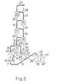
- the preheated pulverulent raw material is divided into two streams by a dividing damper 34.
- the first stream of preheated pulverulent raw material is, via the material outlet duct 22 and a branch 22"', directed to the suspension burning chamber 4 which is constructed similarly to the burning chambers in Figures 1 and 2.
- the suspension transfer duct 8 from the burning chamber is connected to a first suspension inlet opening in the cyclone 9.
- the second stream of preheated pulverulent raw material is, via a branch 22' of the material outlet duct 22, introduced into a kiln gas duct 28 connected to another suspension inlet opening 47 in the cyclone 9.
- the material is preheated in the preheater and divided into two streams by the dividing damper 34.
- the first stream is introduced into the suspension burning chamber 4 and the second stream is introduced into and suspended in kiln exhaust gas as described above.
- the two suspensions are united not in the kiln gas duct 28 but in the cyclone 9.
- the pulverulent raw material may be divided not by dividing the riser pipe 14, but by a dividing damper as shown in Figure 3 and vice versa.
- the pulverulent raw material may be divided not in the last preheating step, but in one of the preceding steps.
- One stream is withdrawn from the preheater as the second stream of pulverulent raw material having a rather low temperature, the other stream being further preheated as the first stream of pulverulent raw material.
- the number of cyclones in the preheaters may be larger or smaller than shown.
- the introduction of the first stream of pulverulent raw material into the suspension burning chamber 4 may comprise division of the stream into two substreams, one being suspended in the oxygen containing gas before this gas is introduced through the bottom of the burning chamber, the other being introduced as a ' coherent stream on a sloping bottom of the burning chamber.
- Additional heat may be provided by burning fuel in the kiln gas duct 28.
- the duct will be provided with a supplementary fuel inlet 45 which, when the kiln gas duct 28 is provided with a retention chamber 29 as shown in Figure 2, is preferably arranged at the bottom of the retention chamber.
- the proportions of waste cooler air flowing through the pipe 3 and kiln 1 may be controlled by means of a throttle 44 in the kiln gas duct 28, or by means of a throttle 46 in the air pipe 3, as exemplified in Figures 1 and 2 respectively.
Landscapes
- Chemical & Material Sciences (AREA)
- Engineering & Computer Science (AREA)
- Ceramic Engineering (AREA)
- Organic Chemistry (AREA)
- Thermal Sciences (AREA)
- Physics & Mathematics (AREA)
- Mechanical Engineering (AREA)
- Structural Engineering (AREA)
- Materials Engineering (AREA)
- General Engineering & Computer Science (AREA)
- Chemical Kinetics & Catalysis (AREA)
- Furnace Details (AREA)
- Feeding, Discharge, Calcimining, Fusing, And Gas-Generation Devices (AREA)
- Curing Cements, Concrete, And Artificial Stone (AREA)
- Crucibles And Fluidized-Bed Furnaces (AREA)
- Manufacture And Refinement Of Metals (AREA)
Claims (7)
Applications Claiming Priority (2)
| Application Number | Priority Date | Filing Date | Title |
|---|---|---|---|
| DK392682A DK151319C (da) | 1982-09-02 | 1982-09-02 | Anlaeg til braending af pulverformet materiale |
| DK3926/82 | 1982-09-02 |
Publications (3)
| Publication Number | Publication Date |
|---|---|
| EP0103423A1 EP0103423A1 (de) | 1984-03-21 |
| EP0103423B1 true EP0103423B1 (de) | 1986-02-19 |
| EP0103423B2 EP0103423B2 (de) | 1993-11-18 |
Family
ID=8128327
Family Applications (1)
| Application Number | Title | Priority Date | Filing Date |
|---|---|---|---|
| EP83304758A Expired - Lifetime EP0103423B2 (de) | 1982-09-02 | 1983-08-17 | Anlage zum Brennen von pulverförmigem Rohmaterial |
Country Status (17)
| Country | Link |
|---|---|
| US (1) | US4561842A (de) |
| EP (1) | EP0103423B2 (de) |
| JP (1) | JPS5962337A (de) |
| KR (1) | KR910000710B1 (de) |
| AU (1) | AU563609B2 (de) |
| BR (1) | BR8304599A (de) |
| CA (1) | CA1212230A (de) |
| DE (1) | DE3362188D1 (de) |
| DK (1) | DK151319C (de) |
| EG (1) | EG15977A (de) |
| ES (1) | ES8500087A1 (de) |
| GR (1) | GR78937B (de) |
| IE (1) | IE55487B1 (de) |
| IN (1) | IN158543B (de) |
| MX (1) | MX156820A (de) |
| PT (1) | PT77253B (de) |
| ZA (1) | ZA834871B (de) |
Families Citing this family (17)
| Publication number | Priority date | Publication date | Assignee | Title |
|---|---|---|---|---|
| US4548580A (en) * | 1981-12-04 | 1985-10-22 | Mitsubishi Jukogyo K.K. | Calcining apparatus for powdery materials |
| DE3420078A1 (de) * | 1984-05-29 | 1985-12-05 | Krupp Polysius Ag, 4720 Beckum | Verfahren und anlage zur waermebehandlung von feinkoernigem gut |
| DE3520056A1 (de) * | 1985-06-04 | 1986-12-04 | O & K Orenstein & Koppel Ag, 1000 Berlin | Verfahren zur waermebehandlung von feinkoernigem gut |
| DE3522883A1 (de) * | 1985-06-26 | 1987-01-08 | Krupp Polysius Ag | Verfahren und anlage zur waermebehandlung von feinkoernigem gut |
| DE3703596A1 (de) * | 1987-02-06 | 1988-08-18 | Kloeckner Humboldt Deutz Ag | Verfahren und vorrichtung zur herstellung von zement aus zementrohmehl |
| US5049198A (en) * | 1988-06-10 | 1991-09-17 | Ribas Roger S | Calcium sulfate process for the coproduction of Portland cement clinker and concentrated sulfur dioxide adequate to manufacture sulfuric acid |
| FR2633039B1 (fr) * | 1988-06-21 | 1991-02-01 | Fives Cail Babcock | Installation pour la fabrication du ciment par voie seche avec four de precalcination |
| DK163089A (da) * | 1989-04-05 | 1990-10-06 | Smidth & Co As F L | Reduktion af emission af nitrogenoxide (nox) fra et ovnanlaeg |
| CA2240442C (en) * | 1996-02-14 | 2003-09-16 | F.L. Smidth & Co. A/S | Method for reducing nox emission from a kiln plant |
| DE19705560A1 (de) * | 1997-02-13 | 1998-08-20 | Krupp Polysius Ag | Verfahren und Anlage zur Herstellung von Zementklinker |
| DK174194B1 (da) * | 1998-02-04 | 2002-09-09 | Smidth & Co As F L | Ovnanlæg, samt fremgangsmåde til fremstilling af cement |
| DE19903954A1 (de) * | 1999-02-02 | 2000-08-03 | Kloeckner Humboldt Wedag | Anlage zur thermischen Behandlung von mehlförmigen Rohmaterialien |
| MXPA01007229A (es) * | 2001-07-13 | 2003-08-19 | Cemex Trademarks Worldwide Ltd | Metodo para producir clinker de cemento utilizando coque de alto contenido de azufre. |
| CN107218803A (zh) * | 2017-06-30 | 2017-09-29 | 上海柯来浦能源科技有限公司 | 一种热效率高的回转窑 |
| CN107739162A (zh) * | 2017-12-01 | 2018-02-27 | 河南中蓝新材料科技有限公司 | 一种利用气体燃料悬浮焙烧粉状活性石灰的焙烧炉系统 |
| CN107840584A (zh) * | 2017-12-01 | 2018-03-27 | 河南中蓝新材料科技有限公司 | 一种采用液体燃料悬浮焙烧粉状活性石灰的焙烧炉 |
| EP3738939A1 (de) * | 2019-05-17 | 2020-11-18 | HeidelbergCement AG | Verfahren zum kalzinieren von rohmehl für die zementklinkerherstellung |
Family Cites Families (15)
| Publication number | Priority date | Publication date | Assignee | Title |
|---|---|---|---|---|
| US3071309A (en) * | 1959-05-11 | 1963-01-01 | Trane Co | Compressor cylinder and unloader apparatus |
| AU471315B2 (en) * | 1972-05-20 | 1976-04-15 | Ishikawajima-Harima Jukogyo K.K. | Apparatus for burning materials of cement andthe luce |
| JPS5527022B2 (de) * | 1972-09-04 | 1980-07-17 | ||
| DE2247172C3 (de) * | 1972-09-26 | 1981-07-02 | Krupp Polysius Ag, 4720 Beckum | Anlage zur Herstellung von Zement, Kalk, Tonerde und dgl. |
| GB1434091A (en) * | 1973-04-30 | 1976-04-28 | Smidth & Co As F L | Plant for burning or heat treatment of granular or pulverous material |
| JPS5072924A (de) * | 1973-10-29 | 1975-06-16 | ||
| FR2250423A5 (en) * | 1973-11-06 | 1975-05-30 | Ishikawajima Harima Heavy Ind | Cement powder preheating - in several stages by kiln waste gases and in parallel stages by combustion gases |
| GB1406965A (en) * | 1973-11-08 | 1975-09-17 | Ishikawajima Harima Heavy Ind | Suspension-type preheating system for powdery raw materials |
| DE2362132C2 (de) * | 1973-12-14 | 1982-03-11 | Klöckner-Humboldt-Deutz AG, 5000 Köln | Einrichtung zur thermischen Behandlung von feinkörnigem Gut mit mehreren einem Wärmetauschersystem zugeordneten Zusatzbrenneinrichtungen |
| JPS5292238A (en) * | 1976-01-12 | 1977-08-03 | Onoda Cement Co Ltd | Method of baking powdery materials of multistage cyclone of auxiliary furnace type and apparatus for carrying out thereof |
| US4071309A (en) * | 1976-05-28 | 1978-01-31 | Allis-Chalmers Corporation | Method and apparatus for making cement with preheater, kiln and heat exchanger for heating combustion air |
| US4063875A (en) * | 1976-05-28 | 1977-12-20 | Allis-Chalmers Corporation | Cement making apparatus including preheater, kiln, cooler and auxiliary furnace |
| US4270900A (en) * | 1980-01-07 | 1981-06-02 | Allis-Chalmers Corporation | Suspension preheater |
| DE3000494A1 (de) * | 1980-01-08 | 1981-07-09 | Krupp Polysius Ag, 4720 Beckum | Verfahren und anlage zur waermebehandlung von feinkoernigem gut |
| DE3164216D1 (en) * | 1980-11-17 | 1984-07-19 | Smidth & Co As F L | Cement burning plant |
-
1982
- 1982-09-02 DK DK392682A patent/DK151319C/da not_active IP Right Cessation
-
1983
- 1983-07-04 ZA ZA834871A patent/ZA834871B/xx unknown
- 1983-07-05 IN IN833/CAL/83A patent/IN158543B/en unknown
- 1983-07-06 AU AU16607/83A patent/AU563609B2/en not_active Ceased
- 1983-08-05 IE IE1858/83A patent/IE55487B1/en unknown
- 1983-08-11 US US06/522,396 patent/US4561842A/en not_active Expired - Lifetime
- 1983-08-15 CA CA000434645A patent/CA1212230A/en not_active Expired
- 1983-08-17 DE DE8383304758T patent/DE3362188D1/de not_active Expired
- 1983-08-17 EP EP83304758A patent/EP0103423B2/de not_active Expired - Lifetime
- 1983-08-25 BR BR8304599A patent/BR8304599A/pt not_active IP Right Cessation
- 1983-08-25 PT PT77253A patent/PT77253B/pt not_active IP Right Cessation
- 1983-08-29 ES ES525207A patent/ES8500087A1/es not_active Expired
- 1983-08-29 GR GR72315A patent/GR78937B/el unknown
- 1983-08-30 MX MX198557A patent/MX156820A/es unknown
- 1983-09-02 KR KR1019830004143A patent/KR910000710B1/ko not_active Expired
- 1983-09-02 JP JP58161779A patent/JPS5962337A/ja active Granted
- 1983-09-03 EG EG539/83A patent/EG15977A/xx active
Also Published As
| Publication number | Publication date |
|---|---|
| ES525207A0 (es) | 1984-10-01 |
| EG15977A (en) | 1986-12-30 |
| DK151319B (da) | 1987-11-23 |
| IN158543B (de) | 1986-12-06 |
| DK392682A (da) | 1984-03-03 |
| US4561842A (en) | 1985-12-31 |
| ZA834871B (en) | 1984-03-28 |
| JPH0380536B2 (de) | 1991-12-25 |
| PT77253A (en) | 1983-09-01 |
| AU563609B2 (en) | 1987-07-16 |
| ES8500087A1 (es) | 1984-10-01 |
| KR910000710B1 (ko) | 1991-01-31 |
| EP0103423B2 (de) | 1993-11-18 |
| KR840005979A (ko) | 1984-11-21 |
| GR78937B (de) | 1984-10-02 |
| MX156820A (es) | 1988-10-05 |
| IE831858L (en) | 1984-03-02 |
| BR8304599A (pt) | 1984-04-24 |
| IE55487B1 (en) | 1990-09-26 |
| AU1660783A (en) | 1984-03-08 |
| EP0103423A1 (de) | 1984-03-21 |
| DK151319C (da) | 1988-05-09 |
| DE3362188D1 (en) | 1986-03-27 |
| JPS5962337A (ja) | 1984-04-09 |
| CA1212230A (en) | 1986-10-07 |
| PT77253B (en) | 1986-02-17 |
Similar Documents
| Publication | Publication Date | Title |
|---|---|---|
| EP0103423B1 (de) | Anlage zum Brennen von pulverförmigem Rohmaterial | |
| AU728011B2 (en) | Fluidized bed process for producing alumina from aluminum hydroxide | |
| US20110034318A1 (en) | Process and plant for the heat treatment of fine-grained mineral solids | |
| KR100425620B1 (ko) | 시멘트 클링커의 제조방법 및 제조장치 | |
| CA1085612A (en) | Apparatus for producing cement clinker | |
| EP0045811B1 (de) | Methode und vorrichtung zur rückgewinnung von wärme, aschen und schwefeloxyden aus den abgasen eines kraftwerkkessels | |
| US4381916A (en) | Method and apparatus for roasting fine grained ores | |
| EP0603998B1 (de) | Verfahren zum Brennen von Kalkstein | |
| US4402754A (en) | Process of producing cement clinker | |
| US4557688A (en) | Method and apparatus for calcining pulverulent raw material | |
| US5800610A (en) | Method for manufacturing cement clinker | |
| GB2127946A (en) | A method of and a plant for burning or roasting fine-grained material | |
| CA1161073A (en) | Process of producing cement clinker | |
| JPH0157064B2 (de) | ||
| US4197137A (en) | Process and apparatus for calcining finely divided cement raw materials including finely divided combustible materials | |
| EP0052925B1 (de) | Verfahren und Anlage zur Behandlung körnigen oder pulverförmigen Rohmaterials | |
| JP4183278B2 (ja) | セメントクリンカの製造プラント及び製造方法 | |
| KR910000709B1 (ko) | 분말원료의 열처리방법과 그 장치 | |
| AU683774C (en) | Method for manufacturing cement clinker in a stationary burning reactor | |
| GB2146747A (en) | Method and apparatus for precalcining pulverous raw material | |
| MXPA99011129A (en) | Method and apparatus for producing cement clinker |
Legal Events
| Date | Code | Title | Description |
|---|---|---|---|
| PUAI | Public reference made under article 153(3) epc to a published international application that has entered the european phase |
Free format text: ORIGINAL CODE: 0009012 |
|
| AK | Designated contracting states |
Designated state(s): BE CH DE FR GB IT LI SE |
|
| 17P | Request for examination filed |
Effective date: 19840828 |
|
| ITF | It: translation for a ep patent filed | ||
| GRAA | (expected) grant |
Free format text: ORIGINAL CODE: 0009210 |
|
| AK | Designated contracting states |
Designated state(s): BE CH DE FR GB IT LI SE |
|
| REF | Corresponds to: |
Ref document number: 3362188 Country of ref document: DE Date of ref document: 19860327 |
|
| ET | Fr: translation filed | ||
| PLBI | Opposition filed |
Free format text: ORIGINAL CODE: 0009260 |
|
| 26 | Opposition filed |
Opponent name: KRUPP POLYSIUS AG Effective date: 19861118 |
|
| ITTA | It: last paid annual fee | ||
| PUAH | Patent maintained in amended form |
Free format text: ORIGINAL CODE: 0009272 |
|
| STAA | Information on the status of an ep patent application or granted ep patent |
Free format text: STATUS: PATENT MAINTAINED AS AMENDED |
|
| 27A | Patent maintained in amended form |
Effective date: 19931118 |
|
| AK | Designated contracting states |
Kind code of ref document: B2 Designated state(s): BE CH DE FR GB IT LI SE |
|
| ET3 | Fr: translation filed ** decision concerning opposition | ||
| REG | Reference to a national code |
Ref country code: CH Ref legal event code: AEN |
|
| ITF | It: translation for a ep patent filed | ||
| EAL | Se: european patent in force in sweden |
Ref document number: 83304758.2 |
|
| APAC | Appeal dossier modified |
Free format text: ORIGINAL CODE: EPIDOS NOAPO |
|
| APAC | Appeal dossier modified |
Free format text: ORIGINAL CODE: EPIDOS NOAPO |
|
| PGFP | Annual fee paid to national office [announced via postgrant information from national office to epo] |
Ref country code: GB Payment date: 19970808 Year of fee payment: 15 |
|
| PGFP | Annual fee paid to national office [announced via postgrant information from national office to epo] |
Ref country code: FR Payment date: 19970811 Year of fee payment: 15 |
|
| PGFP | Annual fee paid to national office [announced via postgrant information from national office to epo] |
Ref country code: SE Payment date: 19970818 Year of fee payment: 15 |
|
| PGFP | Annual fee paid to national office [announced via postgrant information from national office to epo] |
Ref country code: DE Payment date: 19970822 Year of fee payment: 15 |
|
| PGFP | Annual fee paid to national office [announced via postgrant information from national office to epo] |
Ref country code: CH Payment date: 19970911 Year of fee payment: 15 |
|
| PGFP | Annual fee paid to national office [announced via postgrant information from national office to epo] |
Ref country code: BE Payment date: 19971013 Year of fee payment: 15 |
|
| PG25 | Lapsed in a contracting state [announced via postgrant information from national office to epo] |
Ref country code: GB Free format text: LAPSE BECAUSE OF NON-PAYMENT OF DUE FEES Effective date: 19980817 |
|
| PG25 | Lapsed in a contracting state [announced via postgrant information from national office to epo] |
Ref country code: SE Free format text: LAPSE BECAUSE OF NON-PAYMENT OF DUE FEES Effective date: 19980818 |
|
| PG25 | Lapsed in a contracting state [announced via postgrant information from national office to epo] |
Ref country code: LI Free format text: LAPSE BECAUSE OF NON-PAYMENT OF DUE FEES Effective date: 19980831 Ref country code: CH Free format text: LAPSE BECAUSE OF NON-PAYMENT OF DUE FEES Effective date: 19980831 Ref country code: BE Free format text: LAPSE BECAUSE OF NON-PAYMENT OF DUE FEES Effective date: 19980831 |
|
| BERE | Be: lapsed |
Owner name: F.L. SMIDTH & CO. A/S Effective date: 19980831 |
|
| GBPC | Gb: european patent ceased through non-payment of renewal fee |
Effective date: 19980817 |
|
| REG | Reference to a national code |
Ref country code: CH Ref legal event code: PL |
|
| PG25 | Lapsed in a contracting state [announced via postgrant information from national office to epo] |
Ref country code: FR Free format text: LAPSE BECAUSE OF NON-PAYMENT OF DUE FEES Effective date: 19990430 |
|
| EUG | Se: european patent has lapsed |
Ref document number: 83304758.2 |
|
| PG25 | Lapsed in a contracting state [announced via postgrant information from national office to epo] |
Ref country code: DE Free format text: LAPSE BECAUSE OF NON-PAYMENT OF DUE FEES Effective date: 19990601 |
|
| REG | Reference to a national code |
Ref country code: FR Ref legal event code: ST |
|
| APAH | Appeal reference modified |
Free format text: ORIGINAL CODE: EPIDOSCREFNO |