EP0103263A2 - Therapeutische Übungsvorrichtung - Google Patents
Therapeutische Übungsvorrichtung Download PDFInfo
- Publication number
- EP0103263A2 EP0103263A2 EP83108789A EP83108789A EP0103263A2 EP 0103263 A2 EP0103263 A2 EP 0103263A2 EP 83108789 A EP83108789 A EP 83108789A EP 83108789 A EP83108789 A EP 83108789A EP 0103263 A2 EP0103263 A2 EP 0103263A2
- Authority
- EP
- European Patent Office
- Prior art keywords
- frame
- belt
- pool section
- treadmill
- roller
- Prior art date
- Legal status (The legal status is an assumption and is not a legal conclusion. Google has not performed a legal analysis and makes no representation as to the accuracy of the status listed.)
- Withdrawn
Links
Images

Classifications
-
- A—HUMAN NECESSITIES
- A61—MEDICAL OR VETERINARY SCIENCE; HYGIENE
- A61D—VETERINARY INSTRUMENTS, IMPLEMENTS, TOOLS, OR METHODS
- A61D11/00—Washing devices or gaseous curative baths specially adapted to veterinary purposes
-
- A—HUMAN NECESSITIES
- A01—AGRICULTURE; FORESTRY; ANIMAL HUSBANDRY; HUNTING; TRAPPING; FISHING
- A01K—ANIMAL HUSBANDRY; AVICULTURE; APICULTURE; PISCICULTURE; FISHING; REARING OR BREEDING ANIMALS, NOT OTHERWISE PROVIDED FOR; NEW BREEDS OF ANIMALS
- A01K15/00—Devices for taming animals, e.g. nose-rings or hobbles; Devices for overturning animals in general; Training or exercising equipment; Covering boxes
- A01K15/02—Training or exercising equipment, e.g. mazes or labyrinths for animals ; Electric shock devices; Toys specially adapted for animals
- A01K15/027—Exercising equipment, e.g. tread mills, carousels
Definitions
- This invention relates in general to a therapeutic exercising device, and more particularly to improved means for promoting the exercising, conditioning and therapeutic treatment of injured muscles and joints particularly in animals such as race horses, although its principles, teachings and concepts are equally applicable to humans.
- the present invention is directed to an improved combination which is distinguished by the advantages of underwater treadmill for muscle development plus features of the swimming pool or surf running thesis and the corrective thereauptic features of the whirlpool therapy devices.
- an animal or human employing a device according to this invention may experience the combined or selected individual advantages of swimming pool, whirlpool and treadmill therapy.
- the occupant of the device particularly a race horse for example, avoids the disadvantages attendant dry land racetracks and treadmills, enjoys accelerated muscle tone development and may be selectively subjected to the corrective therapy attendant whirlpool jet treatment to promote the healing of tired or injured joints and muscles.
- the invention provides a therapeutic exercising device for hydraulic exercise and therapy treatment, comprising: open top housing means adapted to contain a body of liquid and having entry and exit means communicating with a pool section thereof adapted to be occupied by the user, a well portion in the bottom of said pool section disposed beneath the level of said entry and exit means, endless treadmill means mounted in said well portion and comprising roller supported endless belt means having an upper run presenting a movable undersupport surface over the bottom of said pool section and extending substantially horizontally between said entry and exit means, drive means exteriorly of said housing having driving connection with said treadmill means for actuating the same, control means for effecting selected operational movement speeds of said belt means, and plural hydrotherapy jet means communicating with said pool section for supplying a plurality of jet streams in said body of liquid, whereby the user occupant of the pool section is caused to ambulate in accordance with the speed of movement of said belt means and is subjected to hydrotherapy treatment by operation of said jet means.
- the training device comprises an elongated tank or housing 16 having inclined entry and exit ramp sections 17 and 18 respectively, and a central pool section 19 in which the animal is positioned for exercise and therapy and in the bottom of which is located a submerged treadmill 20 to be described in greater detail presently.
- suitable control means 21 are provided for regulating operation of the device and more particularly, for controlling the circulation and treatment of a body of water by means of filters 22, 22a, heater means 23, sterilizing means 24 and circulating pump means 25.
- the housing 16 preferably is formed in three sections to comprise the inlet ramp section 17, the exit ramp section 18 and the central pool section 19, each of which constitute molded liner portions made of reinforced fiberglass or a similar construction.
- the two ramp sections 17 and 18 are generally identical in formation and comprise a generally wedge-shape cross-sectional configuration as shown best in Fig. 2.
- Each ramp section has a pair of parallel spaced upright side wall portions 30, 31 bordered by a continuous flange apron 32 along the upper edges thereof.
- a bottom wall 33 of each of the ramp sections 17 and 18 may be molded with a plurality of parallel spaced transverse raised clogs or treads 34 to provide a purchase or footing for the animal as it enters and exits the training device.
- the clogs 34 may be eliminated, and the bottom wall 33 built in a planar incline with the clogs then being welded or otherwise attached over the upper face of the bottom wall 33 and comprising wooden members to guard the feet of the animal and to provide a replaceable stepping means to assist the animal in its movement into and out of the central section 19.
- the central or pool section 19 of the housing 16, in contrast to the wedge-shape formation of the two ramp sections 17 and 18 is formed as a substantially open top rectangular box, the opposite ends of which are open and flanged for connection directly with the two ramp sections in assembly.
- the central section also includes a pair of opposing side walls 37, 37. At least one wall 37 is further formed with a laterally projecting vertical elongated housing 38 which accommodates drive means for the treadmill as will be explained more fully hereinafter.
- the housing portion 35 is cast integrally with the one side wall 37 depending on which side of the housing the treadmill drive is located. In the particular embodiment illustrated herein, the housing portion 35 openly communicates with the interior of the pool section 18 although the same may be enclosed except for passage of a drive shaft for the treadmill as will appear presently.
- At least one, and in certain cases, two equipment well portions 39 are also located outboard of and formed integrally with the walls 37, 37 for housing circulating water pumps and plumbing associated with the whirlpool jets which have plural outlets 40, 40 that discharge into the interior of the central section 19.
- whirlpool jet outlets 40, 40 shown in only one side wall 37, it is to be understood that both of the opposing side walls 37, 37 have such outlet jets 40, 40.
- whirlpool jet outlets 40 disposed to circulate jet stream water against the animal's front and back leg sections and muscle areas in which the animal is more likely to receive injury, specifically in the areas of the suspensories, knees, hocks, shoulders and strifles with the outlets 40, 40 in one wall 37 being opposed by the corresponding outlets in the opposite wall to make a total of twelve hydrotherapy jet outlets for the central section 19.
- the flanged ends of the central section abut against opposing ends of the ramp sections 17 and 18 having mating flange construction (not specifically illustrated) to formulate a water tight joint therebetween employing appropriate compression seals and bolts to unify the overall structure of the housing assembly 16.
- the housing 16 may be a unitary structure without seams or joints. This would be preferred for certain smaller installation sizes. Be that as it may, in operation the molded reinforced plastic housing 16 is used as a liner for a poured concrete tank formed about the housing 16 in the manner illustrated in Fig. 5.
- an appropriate opening is excavated to receive the liner housing 16 which is positioned in the hole and spaced from the walls thereof for the reception of a poured concrete vault or encasement 41 thereabout (see Fig. 2).
- the concrete reinforcement for the liner housing 16 is unified into a single poured structure which may be metal reinforced if desired, to afford a rigid and unified structure capable of holding the housing 16 and the weight of the liquid placed therein.
- the central bottom area of the pool section 19 is depressed to provide a wall portion 42 provided with an appropriate drain 43 whereby the liquid contents of the assembled housing 16 may be removed when necessary.
- housing 16 In a typical installation, the dimensions of housing 16 are roughtly thirty-six feet long, seven feet wide and five to six feet deep to permit a water capacity of roughtly twenty-one hundred gallons. These dimensions, size and capacity appear to be satisfactory for accommodating race horses and animals of like size.
- the treadmill assembly 20 is disposed in the bottom well portion 43 of the central or pool section and is permanently installed thereat for supporting the weight of the animal or occupant of the device to effectuate a regulated movement of the limbs as desired. More specifically as best shown in Fig. 2 of the drawings, assembly 20 comprises a main frame 45 made up of a pair of parallel spaced elongated metal side channel members 46, 47 which are rigidly cross connected by parallel spaced box frame members 48, 48; there being five such box frame members in the particular illustrated structure.
- each of the channel sections 49 is provided with an internal plate member 50 welded across the interior thereof and provided with a central threaded opening receptive of an adjustment bolt 51 having the lower end thereof pivotally attached to an upper end plate 52 of a smaller channel portion 53 having a ground engaging foot plate 54 connected across its lower end.
- the two side frame members 46 and 47 are also traversed by an idler roller 60 at one end thereof and a drive roller 61 at the opposite end thereof: the two rollers constituting cylindrical metal rollers suitable for engaging and supporting the endless belt member 56.
- Adjustment means 62 engage bearing means 63 at the ends of support shaft 64 for the idler roller 60 whereby to move such support shaft along a slotted opening 65 formed in the major vertical web of the channel frame members 46 and 47. This assists in roughly tensioning and aligning the treadmill's endless belt 56 about the rollers 60, 61.
- the drive roller 61 unlike idler roller 60, is not adjustable relative to the frame members 46 and 47; such being mounted in fixed position with one end of the support shaft or axle 69 therefor being supported in bearing means mounted in frame member 47 and at the opposite end thereof supported in bearing means 70 carried in an end wall 71 of a laterally extending generally U-shaped support cage 72 (see Fig. 3).
- the drive axle 69 also carries a toothed sprocket wheel 73 located within the open interior of the support cage 72 for engagement with an endless drive chain means 74 which extends upwardly therefrom and is trained about a second drive sprocket 75.
- a shaft 76 associated with a gear reducer 77 and a drive motor 78 therefor supports and rotatably drives sprocket 75 to activate chain 74.
- the motor and gear reducer are mounted on a hinged platform 79 carried at the upper end of a supporting framework comprising parallel spaced vertical uprights 80, 80 and angularly disposed frame members 81, 81 extending upwardly from the support cage 72.
- the treadmill belt support system in particular includes a pair of idler rollers 82, 82, having end support bearings 83, 83 stationarily mounted in the vertical web walls of the side support frames 46, 47 and located substantially one third the distance inwardly from the opposite ends thereof.
- a central idler roller 84 is also provided which is retractably carried in movable bearing blocks 85 having sliding connection with a pair of vertically extending guide rails 86, 86 welded or otherwise rigidly affixed to the outside of the channel frame members 46 and 47, substantially medially of the length of such frame members.
- a suitable adjustment screw means 87 is associated with each block 85 and is available for engagement via an opening 88 formed in the upper flange 89 of each of the two frame members 46 and 47.
- the bearing support blocks 85 may be vertically positioned as selected along the rails 86 to adjust tension of the treadmill belt 56.
- a support platform member 90 Mounted over and affixed to the several box channel support members 48, 48 and extending substantially the length of the side frame members 46 and 47 is a support platform member 90.
- This platform may be made of suitable synthetic material such as reinforced fiberglass, nylon or similar non-corrosive material in sheet form capable of undersupporting the weight of user of the training device, such as the race horse illustrated in Fig. 1.
- the endless treadmill belt 56 is trained over the platform 90 about the two end rollers 60 and 61, above or over the upper side of the two idler rollers 82, 82 and beneath the central idler roller 84 as shown best in Fig. 2. Tensioning of the belt is regulated by the vertical positioning of the guide blocks 85, 85 associated with the central idler with additional adjustment being available via the adjustment means 62, associated with the main idler roller 60, as hereinabove mentioned.
- the entire treadmill assembly 20, as previously noted, is mounted in the bottom well of the tank section 19 of the housing assembly so that the upper run of the belt 56 is substantially level with the lower ends of the two ramp sections 17 and 18 in the manner shown in Fig. 2 of the drawings.
- the rectangular framework supporting the belt means 56 may be diagonally racked or twisted to effectuate a desired lateral train of the belt, or that is, train the same centrally of the two main rollers 60, 61 while the treadmill assembly remains submerged. This is of importance and critical to the successful operation of the training device, particularly with animals which ambulate or run in a manner tending to produce an unbalanced load condition on the treadmill.
- Belt tensioning is readily adjustable by using a reach rod engageable with the upper head ends of the adjustment bolts 88, associated with the movable idler roller 84. Thus, successful operation of the treadmill may be maintained.
- Fig. 5 of the drawings the general features of the water supply and circulating system associated with the tank housing 16 are set forth.
- water within the interior of the tank 16 is circulated by the pump means 25 having a valve controlled supply inlet 95 for supplying fresh water directly to the tank via inlet supply piping 96.
- Water in the tank 16 is subject to the suction side of the pump 25 via drain outlet 43 and line 97 which feeds a pair of filters 22, 22a for the purpose of removing particulates from the water along with other impurities. Water passing through the filters 22, 22a is fed to a heater unit 23 whereby the temperature of the water may be selectively controlled.
- Water discharged from heater 23 is circulated through the sterilizing equipment 24, such as an ozone sterilizer, for purification purposes and thence to the return side of the pump 25 via line 98.
- a valve controlled discharge line 99 permits overboard discharge of the water for draining the tank as necessary.
- the water in the tank 16 is also subject to the effects of the several therapeutic jets 40, 40 in the side walls of the central pool section 19 which provide.directional streams of water mixed with air in a known manner.
- a centrally disposed distribution jet 100 formed as a T, is used for diverting jet streams toward the opposite ends of the tank 16. This effects an orbital water circulation in the tank as indicated by the arrows in Fig. 5.
- an additional such inlet jet is employed on the opposite wall of section 19.
- the incoming jet streams also assist in circulating the fluid in the tank 16 causing impurities such as straw particles, hair and the like to be discharged through the drain outlet 42 connected with the suction outlet line 97 of the circulating water system. It is of vital importance that the water not only circulate in and about the tank 16, but that it be maintained in a moving state throughout the tank for the sake of removing impurities and other ingredients through the filtering and sterilizing means 22 and 24, to avoid contamination. This becomes a particularly serious problem in periods of frequent use, particularly by a large number of animals.
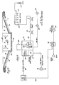
- Control of the liquid in the tank 16 as well as its circulation by the pump means 25 and the regulation of the therapeutic jet means 40, 40 is effected by the control means 21, schematically illustated in Fig. 6.
- a typical control means 21 is supplied from a 100 amp, 220 volt, 60 amp single phase supply over conductor 104 which feeds a main "On-Off" control switch 105.
- a second control switch 106 is provided for controlling energization of a pair of whirlpool circulating motors 107, 107 over a motor starting relay circuit means 108.
- Auxiliary circuit 110 feeds off of the motor starter circuit 108 to supply a pair of 24 volt transformers 111, 112 for supplying one or more jet control switches 113; there being a control switch 113 for each of the jet outlets 40 in the illustrated case.
- the closing of each switch 113 serves to energize an associated solenoid means 114 for operating individual valves (not shown) controlling flow of liquid through an associated outlet jet 40.
- FIG. 6 shows six control switches l13 for the six jets 40 illustrated in Fig. 2, it is to be understood that both walls 37 of the tanks central pool section 19 have opposing jets 40 mounted therein for application to either or both sides of the animal as selected (see Fig. 1) and therefore twelve switches 113 and solenoid controlled valves are employed.
- the individual switch control of the whirlpool jets is shown herein, such is not essential and all jets may be controlled by a single on-off switch on selected numbers thereof may be controlled by switch means as desired.
- Control means 21 also includes a variable speed control unit 115 for regulating the speed of the treadmill motor 78 which motor is supplied over a three phase 220 volt supply conductor 116.
- Motor 78 is in the order of a three horse power, 220 volt gear motor, capable of starting up under the load of the animal standing on the treadmill as it is most difficult to have an animal walk onto a moving treadmill. Further by means of the variable speed control 115 the motor 78 may be regulated to produce a desired rate of movement for the treadmill, thus controlling the rate of exercise for the animal in the pool of water.
- the 100 amp supply also feeds, via conductor 120, a timing clock 121 is provided in circuit with the circulating water pump 25, in the order of a three quarter horse power motor, as well as a one quarter horse power motor associated with the ozone generator or sterilizing means 24.
- a timing clock 121 is provided in circuit with the circulating water pump 25, in the order of a three quarter horse power motor, as well as a one quarter horse power motor associated with the ozone generator or sterilizing means 24.
- the animal when exercising a race horse or similar animal for example, the animal is lead down the ramp 17 onto the upper surface of the treadmill 56 which is undersupported by the platform means 90. In most cases, the animal is tethered in place by suitable bar means placed across the pool both in front and behind the animal or by simple halter tethers anchored to opposite sides of the pool section 19. The timer 121 is then set and the water circulation initiated along with energization of the treadmill motor bringing the treadmill from a standstill position to a desired speed of movement.
- the animal is initially exercised at a gradual walk which may be increased gradually to a desired speed causing the animal to keep up with the movement of the underlying support presented by the moving treadmill surface.
- the animal is forced to ambulate through the hydraulic pool and work against the water much as if he were swimming or running through the surf.
- a desired level of exercise may be achieved. If perchance the animal is injured or has sore muscles, selected activation of the several hydrotherapy jets 40 is brought about, causing high speed water and air streams to move against the affected muscular area etc.
- Thermal level of the water temperature is regulated by the heater means 23.
- the filter system preferably comprising a first vacuum filter 22 followed by a sand filter 22a with the sanitizing means preferably being an ionized oxygen bacterial treatment system capable of controlling bacteria level with the generation of ionized oxygen and the intermixture thereof with the circulating water.
- the filter system preferably comprising a first vacuum filter 22 followed by a sand filter 22a with the sanitizing means preferably being an ionized oxygen bacterial treatment system capable of controlling bacteria level with the generation of ionized oxygen and the intermixture thereof with the circulating water. This normally eliminates the need for eye and skin irritating chemicals such as chlorine in the liquid bath.
Landscapes
- Life Sciences & Earth Sciences (AREA)
- Health & Medical Sciences (AREA)
- Environmental Sciences (AREA)
- General Health & Medical Sciences (AREA)
- Veterinary Medicine (AREA)
- Animal Behavior & Ethology (AREA)
- Zoology (AREA)
- Animal Husbandry (AREA)
- Biodiversity & Conservation Biology (AREA)
- Engineering & Computer Science (AREA)
- Physical Education & Sports Medicine (AREA)
- Wood Science & Technology (AREA)
- Public Health (AREA)
- Rehabilitation Tools (AREA)
- Massaging Devices (AREA)
Applications Claiming Priority (2)
| Application Number | Priority Date | Filing Date | Title |
|---|---|---|---|
| US41698582A | 1982-09-13 | 1982-09-13 | |
| US416985 | 1982-09-13 |
Publications (2)
| Publication Number | Publication Date |
|---|---|
| EP0103263A2 true EP0103263A2 (de) | 1984-03-21 |
| EP0103263A3 EP0103263A3 (de) | 1986-03-26 |
Family
ID=23652131
Family Applications (1)
| Application Number | Title | Priority Date | Filing Date |
|---|---|---|---|
| EP83108789A Withdrawn EP0103263A3 (de) | 1982-09-13 | 1983-09-06 | Therapeutische Übungsvorrichtung |
Country Status (8)
| Country | Link |
|---|---|
| EP (1) | EP0103263A3 (de) |
| JP (1) | JPS59135052A (de) |
| AU (1) | AU536611B2 (de) |
| CA (1) | CA1201342A (de) |
| ES (1) | ES8501198A1 (de) |
| GB (1) | GB2127267B (de) |
| NZ (1) | NZ205415A (de) |
| PT (1) | PT77325B (de) |
Cited By (2)
| Publication number | Priority date | Publication date | Assignee | Title |
|---|---|---|---|---|
| WO1991001162A1 (en) * | 1989-07-18 | 1991-02-07 | Stefano Weisz | Hydrotherapy device with underwater treadmill |
| US8667622B2 (en) | 2005-02-09 | 2014-03-11 | Syspal Limited | Hydrotherapy apparatus |
Families Citing this family (17)
| Publication number | Priority date | Publication date | Assignee | Title |
|---|---|---|---|---|
| FR2607389A1 (fr) * | 1986-12-02 | 1988-06-03 | Leonaggeo Angelo | Appareil d'exercice et d'hydrotherapie a tapis roulant monte sur un elevateur, notamment pour chevaux de course |
| US4944506A (en) * | 1987-02-12 | 1990-07-31 | Edmonds Medical Systems, Inc. | Exercise device with underwater treadmill |
| US5108088A (en) * | 1987-02-12 | 1992-04-28 | Stewart Medical, Inc. | Exercise device with underwater treadmill |
| US5002015A (en) * | 1988-12-09 | 1991-03-26 | Aerotrace Hydraulics, Inc. | Submerged treadmill system for exercising animals |
| DE3911370C2 (de) * | 1989-04-07 | 1998-03-12 | Equitech Beteiligungsgesellsch | Trainingsbecken für Tiere |
| JPH0697925B2 (ja) * | 1989-06-12 | 1994-12-07 | 株式会社タクマ | 底板が昇降可能な動物トレーニング用のプール |
| US5302162A (en) * | 1992-11-05 | 1994-04-12 | Precor Incorporated | Exercise treadmill with tension-limited belt adjustment |
| US5921025A (en) * | 1998-01-20 | 1999-07-13 | Gregory J. Smith | Self-watering plant pot |
| DE19927692C2 (de) * | 1999-06-17 | 2001-04-26 | Tech Zentrum Entwicklungs & Ha | Wasserumlaufkanal insbesondere zur Nutzung durch Pferde für den Rennsport |
| JP2007300881A (ja) * | 2006-05-15 | 2007-11-22 | Tadashi Murahira | 動物用プール |
| JP2007319118A (ja) * | 2006-06-02 | 2007-12-13 | Tadashi Murahira | 動物用運動装置 |
| JP2007330195A (ja) * | 2006-06-16 | 2007-12-27 | Tadashi Murahira | 動物用水慣れ器具 |
| GB2441115A (en) * | 2006-08-26 | 2008-02-27 | Nicholas Saville | Treatment tank for horses |
| PL233488B1 (pl) * | 2017-11-20 | 2019-10-31 | Univ Przyrodniczy W Lublinie | Bieżnia do badań koni zaprzęgowych w warunkach zmiennego obciążenia |
| PL233487B1 (pl) * | 2017-11-20 | 2019-10-31 | Univ Przyrodniczy W Lublinie | Bieżnia do badań koni zaprzęgowych w warunkach zmiennego obciążenia |
| PL71038Y1 (pl) * | 2017-11-20 | 2019-10-31 | Univ Przyrodniczy W Lublinie | Bieżnia do badań koni i kuców |
| CN112220584B (zh) * | 2020-10-30 | 2022-07-08 | 济南深蓝动物保健品有限公司 | 一种畜牧兽医用蹄部药浴装置 |
Family Cites Families (4)
| Publication number | Priority date | Publication date | Assignee | Title |
|---|---|---|---|---|
| DK253574A (da) * | 1974-05-09 | 1975-11-10 | Mark & Wedell Ap S | Ergometer |
| US4197815A (en) * | 1978-05-30 | 1980-04-15 | Stran Corporation | Aquatic exercise facility for animals |
| FR2462179A1 (fr) * | 1979-07-26 | 1981-02-13 | Bergeret Jean | Installation pour entrainer des animaux a la course |
| US4332217A (en) * | 1980-08-11 | 1982-06-01 | Talbot-Carlson, Inc. | Controlled rate exerciser and method of conditioning |
-
1983
- 1983-05-10 AU AU14438/83A patent/AU536611B2/en not_active Ceased
- 1983-08-29 NZ NZ20541583A patent/NZ205415A/en unknown
- 1983-09-02 GB GB08323586A patent/GB2127267B/en not_active Expired
- 1983-09-06 EP EP83108789A patent/EP0103263A3/de not_active Withdrawn
- 1983-09-09 PT PT7732583A patent/PT77325B/pt unknown
- 1983-09-12 ES ES525539A patent/ES8501198A1/es not_active Expired
- 1983-09-12 CA CA000436486A patent/CA1201342A/en not_active Expired
- 1983-09-12 JP JP58166840A patent/JPS59135052A/ja active Pending
Cited By (3)
| Publication number | Priority date | Publication date | Assignee | Title |
|---|---|---|---|---|
| WO1991001162A1 (en) * | 1989-07-18 | 1991-02-07 | Stefano Weisz | Hydrotherapy device with underwater treadmill |
| US5295929A (en) * | 1989-07-18 | 1994-03-22 | Stefano Weisz | Hydrotherapy device with underwater treadmill |
| US8667622B2 (en) | 2005-02-09 | 2014-03-11 | Syspal Limited | Hydrotherapy apparatus |
Also Published As
| Publication number | Publication date |
|---|---|
| JPS59135052A (ja) | 1984-08-03 |
| ES525539A0 (es) | 1984-11-16 |
| AU536611B2 (en) | 1984-05-17 |
| AU1443883A (en) | 1984-03-22 |
| EP0103263A3 (de) | 1986-03-26 |
| ES8501198A1 (es) | 1984-11-16 |
| GB2127267B (en) | 1986-01-29 |
| GB8323586D0 (en) | 1983-10-05 |
| NZ205415A (en) | 1986-04-11 |
| PT77325A (en) | 1983-10-01 |
| CA1201342A (en) | 1986-03-04 |
| PT77325B (en) | 1986-02-04 |
| GB2127267A (en) | 1984-04-11 |
Similar Documents
| Publication | Publication Date | Title |
|---|---|---|
| CA1201342A (en) | Therapeutic exercising device | |
| US4918766A (en) | Hydrotherapy exercising device with scissor lift treadmill | |
| US4938469A (en) | Aquatic exercise apparatus | |
| US3485213A (en) | Animal exercising,conditioning and therapy and apparatus therefor | |
| DE69024375T2 (de) | Unterwasserlaufbandvorrichtung für hydrotherapie | |
| US4332217A (en) | Controlled rate exerciser and method of conditioning | |
| US5002015A (en) | Submerged treadmill system for exercising animals | |
| US4379438A (en) | Horse spa | |
| US4197815A (en) | Aquatic exercise facility for animals | |
| US4574739A (en) | Horse exercising device | |
| CA1303925C (en) | Water jet massage apparatus | |
| US4165714A (en) | Animal handling systems | |
| US4183329A (en) | Whirlpool therapy facility and method of treatment | |
| KR101033835B1 (ko) | 애완동물용 수중러닝머신 | |
| EP0845249B1 (de) | Tierbehandlungsvorrichtung | |
| CA3116143A1 (en) | Device for dry massage by means of water jets | |
| KR20130061983A (ko) | 경주마 훈련용 런닝머신 | |
| GB2200548A (en) | Exercising and massaging device | |
| US4291646A (en) | Whirlpool therapy facility and method of treatment | |
| US20110185979A1 (en) | Mobile horse exercise and hydrotherapy system | |
| DE19963583A1 (de) | Aqua-Trainer für Menschen | |
| KR100574469B1 (ko) | 수중운동치료를 위한 장치 및 그 운용방법 | |
| DE20100922U1 (de) | Fahrbarer Aqua-Trainer | |
| JP2006271227A (ja) | 小動物用の運動器具 | |
| EP0401487A2 (de) | Trainingsbecken für Tiere, insbesondere für Pferde |
Legal Events
| Date | Code | Title | Description |
|---|---|---|---|
| PUAI | Public reference made under article 153(3) epc to a published international application that has entered the european phase |
Free format text: ORIGINAL CODE: 0009012 |
|
| AK | Designated contracting states |
Designated state(s): BE DE FR IT |
|
| PUAL | Search report despatched |
Free format text: ORIGINAL CODE: 0009013 |
|
| AK | Designated contracting states |
Kind code of ref document: A3 Designated state(s): BE DE FR IT |
|
| 17P | Request for examination filed |
Effective date: 19860926 |
|
| 17Q | First examination report despatched |
Effective date: 19880323 |
|
| STAA | Information on the status of an ep patent application or granted ep patent |
Free format text: STATUS: THE APPLICATION IS DEEMED TO BE WITHDRAWN |
|
| 18D | Application deemed to be withdrawn |
Effective date: 19891209 |