EP0102905A1 - Method and apparatus for the helical bending of the tubes of a tube coiling of a steam generator - Google Patents
Method and apparatus for the helical bending of the tubes of a tube coiling of a steam generator Download PDFInfo
- Publication number
- EP0102905A1 EP0102905A1 EP83401744A EP83401744A EP0102905A1 EP 0102905 A1 EP0102905 A1 EP 0102905A1 EP 83401744 A EP83401744 A EP 83401744A EP 83401744 A EP83401744 A EP 83401744A EP 0102905 A1 EP0102905 A1 EP 0102905A1
- Authority
- EP
- European Patent Office
- Prior art keywords
- hub
- tubes
- tube
- winding
- around
- Prior art date
- Legal status (The legal status is an assumption and is not a legal conclusion. Google has not performed a legal analysis and makes no representation as to the accuracy of the status listed.)
- Granted
Links
Images

Classifications
-
- B—PERFORMING OPERATIONS; TRANSPORTING
- B21—MECHANICAL METAL-WORKING WITHOUT ESSENTIALLY REMOVING MATERIAL; PUNCHING METAL
- B21D—WORKING OR PROCESSING OF SHEET METAL OR METAL TUBES, RODS OR PROFILES WITHOUT ESSENTIALLY REMOVING MATERIAL; PUNCHING METAL
- B21D53/00—Making other particular articles
- B21D53/02—Making other particular articles heat exchangers or parts thereof, e.g. radiators, condensers fins, headers
- B21D53/027—Making other particular articles heat exchangers or parts thereof, e.g. radiators, condensers fins, headers by helically or spirally winding elongated elements
-
- B—PERFORMING OPERATIONS; TRANSPORTING
- B21—MECHANICAL METAL-WORKING WITHOUT ESSENTIALLY REMOVING MATERIAL; PUNCHING METAL
- B21D—WORKING OR PROCESSING OF SHEET METAL OR METAL TUBES, RODS OR PROFILES WITHOUT ESSENTIALLY REMOVING MATERIAL; PUNCHING METAL
- B21D11/00—Bending not restricted to forms of material mentioned in only one of groups B21D5/00, B21D7/00, B21D9/00; Bending not provided for in groups B21D5/00 - B21D9/00; Twisting
- B21D11/06—Bending into helical or spiral form; Forming a succession of return bends, e.g. serpentine form
Definitions
- the present invention relates to a method for performing the serpentinage tubes constituting the tube of a steam generator beam, in particular a steam generator sodium-water-type u "used in a fast neutron nuclear power station.
- the invention also relates to the device enabling this serpentine to be produced in accordance with the method.
- Certain steam generators comprise a tubular bundle made up of a plurality of tubes wound helically around a cylindrical hub, these tubes thus constituting around the hub several concentric layers regularly spaced apart.
- a tube bundle there are also provided between each layer of tubes, support pieces intended to keep all of the tubes regularly spaced.
- the invention therefore aims to overcome the drawbacks mentioned above, in order to allow the construction, under good conditions, of a steam generator of the "sc dium-water" type generally used in a fast neutron nuclear power plant.
- the present invention relates more precisely to a method of serpentinizing the tubes constituting the tubular bundle of a steam generator, the tubes having to be wound helically around a cylindrical hub, in several successive concentric layers regularly spaced apart.
- this method consists in constituting a plurality of straight tubes, then bending one of the end parts of each of these tubes, the radius of curvature thus obtained substantially corresponding to the radius of winding of the tube , then fix the end of the curved part of one or more tubes on the cylindrical hub or on a part linked to the cylindrical hub, then animate the hub with a simultaneous movement of rotation and longitudinal translation in order to wind the tube (s) in a spiral around the hub, during this winding operation the straight part of the tubes being guided, in the vicinity of the hub, using guide elements mounted fixed, and finally to bend on the hub l another end of the tube or tubes which have just been wound simultaneously, in order to complete the winding.
- the invention also relates to the device making it possible to set up works the serpentine method which is the subject of the invention.
- this device essentially consists of a machine comprising a frame provided with rollers rolling on rectilinear rails, a motor pinion engaged on a rectilinear rack parallel to the rails, a rotating spindle drive coupled to the cylindrical hub of the steam generator, support rollers arranged at both ends of the cylindrical hub, allowing the hub to rotate about its axis arranged parallel to the rails, and a transmission establishing a constant relationship between the rotation of the spindle and that of the drive pinion, in order to obtain the simultaneous movement, of constant ratio, of rotation of the hub and of translation of the whole of the machine supporting the hub, the transmission ratio being determined as a function of the angle of inclination of the helical winding of the tubes around the hub.
- the object of the invention is to produce the helical tube bundle of a high power steam generator.
- the first operation consists in producing a large number of straight tubes 1 of great length. This length of the tubes can be, for example, of the order of 100 meters.
- These tubes 1 are generally produced from several sections of tubes connected end to end by welds 2, 3. Once these tubes have been produced and stored, one of these tubes is seized and a bending operation is carried out on one of its ends so that the curvature thus obtained has a radius equal to the radius of winding of the tube on a hub. Then, as shown in FIG. 4, this tube is thus bent on the cylindrical hub 4 of the steam generator, mounted on a machine 5.
- the end 6 of the tube is attached to the hub 4, near one of the ends of the hub, and there is, on the rectilinear part of the tube, in the vicinity of the machine 5, a guide 7 mounted fixed relative to the ground 8.
- a guide 7 mounted fixed relative to the ground 8.
- the part of the tube bent before the winding of the tube around the hub ( Figure 3) the shape of a helix whose angle of inclination is identical to that of the helical winding of the tube around the hub.
- This part of the tube bent before the tube is wound around the hub may extend, preferably, approximately half a turn.
- Cam shown in Figure 2 before any tube bending operation, one can form a short distance from the ends of the tubes of the elbows so that each tube, once wrapped around the hub, has its two ends oriented longitudinally relative to the hub.
- FIGS. 7 to 9 there will be described a device making it possible to serpentine the tubes constituting the tubular bundle of steam generator according to the method which has been described previously.
- This device essentially consists of a machine 11 which comprises a frame 12 provided with rollers 13 rolling on rails 14 rectilinear and parallel, a driving pinion 15 engaged on a rack 16 rectilinear parallel to the rails, a rotating spindle 17 driving coupled to cylindrical hub 4 of the steam generator, and support rollers 18 disposed at the two ends of the cylindrical hub 4, allowing the hub 4 to rotate about its axis 9 arranged parallel to the rails.
- the machine further comprises a transmission establishing a constant ratio between the rotation of the spindle 17 and that of the drive pinion 15, in order to obtain the simultaneous movement of constant ratio between the rotational movement of the hub 4 and the translational movement of the 'assembly of the machine 11 supporting the hub 4, the transmission ratio being determined as a function of the angle of inclination of the helical winding of the tubes around the hub.
- the machine may further include a secondary frame 19 which can move longitudinally relative to the frame 12 of the machine while being guided using slides 20, this frame 19 being intended to support a part 21 constituting a guide for the tubes. to roll up.
- a secondary frame 19 which can move longitudinally relative to the frame 12 of the machine while being guided using slides 20, this frame 19 being intended to support a part 21 constituting a guide for the tubes. to roll up.
- the machine 11 operates in the following manner: after bending the end part of the tubes, hook their end 6 on the hub 4, then start the machine which rotates the hub 4 while moving longitudinally, which causes the helical winding of tubes around the hub 4.
- the rotation of the drive pinion 15 is stopped, in order to stop the longitudinal movement of the machine 11, the guide 21 is moved so as to bring it into contact with the unrolled end of the tubes, then continue to rotate the hub 4 by longitudinally moving the frame 19 supporting the guide 21 relative to the frame 12 of the machine. In this way, the helical winding of the tubes can be carried out as close as possible to the end of the hub 4.
- the free end of the tubes is then bent in order to completely end their winding around the cylinder, this bending giving the tube a helical shape identical to that of winding the tube around the hub.
- the different plies of tubes are held in place by means of parts supports 25. If, during the winding of the tubes has only the support parts 25, the tubes may not take a perfectly circular shape because one cannot have a very large number of support parts 25 over the entire periphery. It is then possible to have, between two consecutive support pieces 25, pieces 26 arranged longitudinally, over the entire length of the hub 4, these pieces 26 having the shape of a flattened bar. A large number of these bars 26 are thus arranged all around the layer of previously wound tubes, their median plane being arranged radially.
Abstract
Description
La présente invention concerne un procédé permettant de réaliser le serpentinage des tubes constituant le faisceau tubulaire d'un générateur de vapeur, en particulier d'un générateur de vapeur du type usodium-eau" utilisé dans une centrale nucléaire à neutrons rapides. L'invention concerne aussi le dispositif permettant de réaliser ce serpentinage conformément au procédé.The present invention relates to a method for performing the serpentinage tubes constituting the tube of a steam generator beam, in particular a steam generator sodium-water-type u "used in a fast neutron nuclear power station. The The invention also relates to the device enabling this serpentine to be produced in accordance with the method.
Certains générateurs de vapeur comportent un faisceau tubulaire conposé d'une pluralité de tubes enroulés hélicoïdalement autour d'un moyeu cylindrique, ces tubes constituant ainsi autour du moyeu plusieurs couches concentriques régulièrement espacées entre elles. Dans un tel faisceau tubulaire, il est en outre prévu entre chaque couche de tubes, des pièces support destinées à maintenir l'ensemble des tubes régulièrement espacés.Certain steam generators comprise a tubular bundle made up of a plurality of tubes wound helically around a cylindrical hub, these tubes thus constituting around the hub several concentric layers regularly spaced apart. In such a tube bundle, there are also provided between each layer of tubes, support pieces intended to keep all of the tubes regularly spaced.
De nombreuses difficultés apparaissent lors de la réalisation d'un tel faisceau tubulaire constitué de tubes enroulés hélicoïdalement. Il est en effet indispensable d'enrouler ces tubes en ayant la garantie d'un positionnement très rigoureux. Il faut donc prendre toutes les dispositions nécessaires pour obtenir à la fois un rayon de courbure du tube enroulé, un espacement entre chaque tube ainsi qu'un angle d'inclinaison d'enroulement parfaitement déterminés et constants. Devant ces exigences particulières, il est apparu que les procédés courants de serpentinage ne convenaient pas.Many difficulties arise during the production of such a tube bundle consisting of helically wound tubes. It is indeed essential to wind these tubes with the guarantee of a very rigorous positioning. It is therefore necessary to take all the necessary measures to obtain at the same time a radius of curvature of the rolled up tube, a spacing between each tube as well as a perfectly determined and constant angle of inclination of winding. Faced with these particular requirements, it appeared that the current serpentine processes were not suitable.
On peut imaginer, par exemple, de disposer un moyeu cylindrique sur des paliers de façon à ce qu'il soit mobile en rotation, d'attacher l'extrémité d'un ou plusieurs tubes droits au voisinage d'une extrémité du moyeu cylindrique, puis de faire tourner ce moyeu de façon à enrouler hélicoïdalement autour de ce moyeu le ou les tubes. Un tel système de serpentinage présente l'inconvénient de solliciter très fortement en traction le point d'attache de l'extrémité du tube sur le moyeu, lors du commencement de l'opération d'enroulement, et par conséquent il existe un risque certain de détérioration de l'extrémité du tube, au niveau de sa liaison sur le moyeu.One can imagine, for example, to have a cylindrical hub on bearings so that it is movable in rotation, to attach the end of one or more straight tubes in the vicinity of one end of the cylindrical hub, then rotate this hub so as to wind helically around this hub the tube or tubes. Such a serpentine system has the drawback of very strongly tensile stressing the point of attachment of the end of the tube to the hub, when the winding operation begins, and therefore there is a certain risk of deterioration of the end of the tube, at its connection to the hub.
D'autre part, avec un tel système, il est pratiquement impossible de garantir la constance de l'angle d'hélice, parcequ'il est nécessaire de déplacer l'ensemble des tubes selon une direction parallèle à l'axe de rotation du moyeu, pendant l'opération d'enroulement. Un tel guidage et déplacement des tubes est difficilement réalisable, vu la longueur généralement grande de ces tubes. On ne peut en effet envisager de déplacer latéralement un ensemble de plusieurs tubes droits faisant, par exenple, 100 mètres de long, en garantissant une grande précision dans le mouvement. Il faut alors admettre une approximation en prévoyant uniquement le contrôle du déplacement des tubes selon une direction parallèle à l'axe du moyeu en utilisant seulement des éléments de guidage des tubes disposés à proximité du moyen. Il faut alors coopter sur la flexibilité de la partie droite des tubes pour que le dispositif de guidage et de déplacment des tubes garde une efficacité. Un tel système de serpentinage ,n'est donc pas entièrement satisfaisant lorsqu'il est utilisé pour la construction d'un faisceau tabulaire hélicoïdal nécessitant de grandes exigences en matière de précision et de qualité, ce qui est, par exenple, le cas d'un faisceau tubulaire hélicoïdal d'un générateur de vapeur utilisant comme fluide calcporteur du sodium liquide, et utilisé généralement dans une centrale nucléaire à neutrons rapides.On the other hand, with such a system, it is practically impossible to guarantee the constancy of the helix angle, because it is necessary to move the assembly of the tubes in a direction parallel to the axis of rotation of the hub. , during the winding operation. Such guidance and moves It is difficult to produce tubes, given the generally large length of these tubes. One cannot in fact envisage moving laterally a set of several straight tubes making, for example, 100 meters long, guaranteeing high precision in the movement. It is then necessary to admit an approximation by providing only the control of the displacement of the tubes in a direction parallel to the axis of the hub by using only elements of guide of the tubes arranged near the means. It is then necessary to cooperate on the flexibility of the straight part of the tubes so that the device for guiding and moving the tubes retains an efficiency. Such a serpentine system is therefore not entirely satisfactory when it is used for the construction of a helical tabular beam requiring great demands in terms of precision and quality, which is, for example, the case of a helical tube bundle of a steam generator using liquid sodium as a transport medium and generally used in a fast neutron nuclear power plant.
L'invention vise par conséquent à pallier les inconvénients précédemment cités, en vue de permettre la construction, dans de bonnes conditions, d'un générateur de vapeur du type "sc dium-eau" utilisé généralement dans une centrale nucléaire à neutrons rapides.The invention therefore aims to overcome the drawbacks mentioned above, in order to allow the construction, under good conditions, of a steam generator of the "sc dium-water" type generally used in a fast neutron nuclear power plant.
La présente invention concerne plus précisément un procédé de serpentinage des tubes constituant le faisceau tubulaire d'un générateur de vapeur, les tubes devant être enroulés hélicoïdalement autour d'un moyeu cylindrique, en plusieurs couches concentriques successives régulièrement espacées.The present invention relates more precisely to a method of serpentinizing the tubes constituting the tubular bundle of a steam generator, the tubes having to be wound helically around a cylindrical hub, in several successive concentric layers regularly spaced apart.
Selon une caractéristique essentielle de l'invention, ce procédé consiste à constituer une pluralité de tubes rectilignes, à cintrer ensuite l'une des parties extrêmes de chacun de ces tubes, le rayon de courbure ainsi obtenu correspondant sensiblement au rayon d'enroulement du tube, à fixer ensuite l'extrémité de la partie cintrée d'un ou de plusieurs tubes sur le moyeu cylindrique ou sur une pièce liée au moyeu cylindrique, puis à animer le moyeu d'un mouvement simultané de rotation et de translation longitudinale afin d'enrouler en spirale autour du moyeu le ou les tubes, pendant cette opération d'enroulement la partie droite des tubes étant guidée, au voisinage du moyeu, à l'aide d'éléments de guidage montés fixes, et enfin à cintrer sur le moyeu l'autre partie extrême du tube ou des tubes venant d'être enroulés simultanément, afin d'achever l'enroulement.According to an essential characteristic of the invention, this method consists in constituting a plurality of straight tubes, then bending one of the end parts of each of these tubes, the radius of curvature thus obtained substantially corresponding to the radius of winding of the tube , then fix the end of the curved part of one or more tubes on the cylindrical hub or on a part linked to the cylindrical hub, then animate the hub with a simultaneous movement of rotation and longitudinal translation in order to wind the tube (s) in a spiral around the hub, during this winding operation the straight part of the tubes being guided, in the vicinity of the hub, using guide elements mounted fixed, and finally to bend on the hub l another end of the tube or tubes which have just been wound simultaneously, in order to complete the winding.
L'invention concerne aussi le dispositif permettant de mettre en oeuvre le procédé de serpentinage objet de l'invention.The invention also relates to the device making it possible to set up works the serpentine method which is the subject of the invention.
Selon une caractéristique essentielle de l'invention, ce dispositif se compose essentiellement d'une machine comprenant un bâti muni de galets roulant sur des rails rectilignes, d'un pignon moteur en prise sur une crémaillère rectiligne parallèle aux rails, d'une broche tournante motrice accouplée au moyeu cylindrique du générateur de vapeur, de galets supports disposés aux deux extrémités du moyeu cylindrique, permettant au moyeu de tourner autour de son axe disposé parallèlement aux rails, et d'une transmission établissant un rapport constant entre la rotation de la broche et celle du pignon moteur, afin d'obtenir le mouvement simultané, de rapport constant, de rotation du moyeu et de translation de l'ensemble de la machine supportant le moyeu, le rapport de transmission étant déterminé en fonction de l'angle d'inclinaison de l'enroulement hélicoïdal des tubes autour du moyeu.According to an essential characteristic of the invention, this device essentially consists of a machine comprising a frame provided with rollers rolling on rectilinear rails, a motor pinion engaged on a rectilinear rack parallel to the rails, a rotating spindle drive coupled to the cylindrical hub of the steam generator, support rollers arranged at both ends of the cylindrical hub, allowing the hub to rotate about its axis arranged parallel to the rails, and a transmission establishing a constant relationship between the rotation of the spindle and that of the drive pinion, in order to obtain the simultaneous movement, of constant ratio, of rotation of the hub and of translation of the whole of the machine supporting the hub, the transmission ratio being determined as a function of the angle of inclination of the helical winding of the tubes around the hub.
D'autres caractéristiques et avantages de l'invention apparaîtront lors de la description détaillée de l'exemple de réalisation qui va suivre, illustrée par les dessins annexés.Other characteristics and advantages of the invention will become apparent from the detailed description of the embodiment which follows, illustrated by the appended drawings.
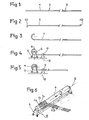
- Les figures 1 à 5 montrent les étapes successives du procédé de serpentinage selon l'invention.Figures 1 to 5 show the successive stages of the serpentine method according to the invention.
- La figure 1 montre un tube de grande longueur destiné à être ser- pentiné selon le procédé de l'invention.FIG. 1 shows a very long tube intended to be serpentine according to the method of the invention.
- La figure 2 montre une variante de réalisation du tube.Figure 2 shows an alternative embodiment of the tube.
- La figure 3 montre schématiquement une première opération du procédé selon l'invention.FIG. 3 schematically shows a first operation of the method according to the invention.
- La figure 4 montre schématiquement l'opération suivante du procédé selon l'invention.FIG. 4 schematically shows the following operation of the method according to the invention.
- La figure 5 montre schématiquement la dernière opération du procédé selon l'invention.FIG. 5 schematically shows the last operation of the method according to the invention.
- La figure 6 montre schématiquement, en perspective, l'opération de serpentinage conforme au procédé selon l'invention.Figure 6 shows schematically, in perspective, the serpentine operation according to the method according to the invention.
- La figure 7 montre, en vue longitudinale, une machine permettant de réaliser l'opération de serpentinage conforme au procédé selon l'invention.Figure 7 shows, in longitudinal view, a machine for carrying out the serpentine operation according to the method according to the invention.
- La figure 8 représente la même machine selon une coupe transversale A-A.Figure 8 shows the same machine in cross-section A-A.
- La figure 9 représente en coupe partielle D-D le faisceau tubulaire.Figure 9 shows in partial section D-D the tube bundle.
En se reportant aux figures 1 à 6, en va décrire les étapes successives du procédé de serpentinage conforme à l'invention.Referring to Figures 1 to 6, will describe the steps suc termination of the serpentine process according to the invention.
Le but de l'invention est de réaliser le faisceau tubulaire hélicoïdal d'un générateur de vapeur de grande puissance. La première opération consiste à réaliser un grand nombre de tubes rectilignes 1 de grande longueur. Cette longueur des tubes peut être par exemple, de l'ordre de 100 mètres. Ces tubes 1 sont généralement réalisés à partir de plusieurs tronçons de tubes reliés bout à bout par des soudures 2, 3. Une fois ces tubes réalisés et stockés, on saisit un de ces tubes et on réalise une opération de cintrage d'une de ses extrémités de façon que la courbure ainsi obtenue présente un rayon égal au rayon d'enroulement du tube sur un moyeu. Ensuite, comme représenté en figure 4, on dispose ce tube ainsi cintré sur le moyeu cylindrique 4 du générateur de vapeur, monté sur une machine 5. On attache l'extrémité 6 du tube sur le moyeu 4, au voisinage d'une des extrémités du moyeu, et on dispose, sur la partie rectiligne du tube, au voisinage de la machine 5, un guide 7 monté fixe par rapport au sol 8. On procède alors à l'enroulement hélicoïdal du tube 1 autour du moyeu cylindrique 4 en animant ce moyeu 4 simultanément, d'un mouvement de rotation autour de son axe longitudinal 9 et d'un mouvement de translation le long de ce même axe 9. On peut enrouler un seul tube 1 hélicoldalement sur le moyeu 4, mais on peut aussi enrouler ainsi simultanément plusieurs tubes la, lb, lc, sur le moyeu 4, conne représenté dans la figure schématique 6.The object of the invention is to produce the helical tube bundle of a high power steam generator. The first operation consists in producing a large number of
Il est préférable de donner à la partie du tube cintrée avant l'enroulement du tube autour du moyeu (figure 3) la forme d'une hélice dont l'angle d'inclinaison est identique à celui de l'enroulement hélicoïdal du tube autour du moyeu. Cette partie du tube cintrée avant l'enroulement du tube autour du moyeu, peut s'étendre, de préférence, approximativement sur un demi-tour. Dans la pratique, il est nécessaire de procéder au cintrage de cette partie du tube sur un gabarit de forme hélicoïdale, d'angle d'inclinaison identique à celui-ci de l'enroulement hélicoïdal du tube autour du moyeu, et de diamètre légèrement plus faible que le diamètre d'enroulement du tube, afin de tenir compte du retour élastique du tube après cintrage.It is preferable to give the part of the tube bent before the winding of the tube around the hub (Figure 3) the shape of a helix whose angle of inclination is identical to that of the helical winding of the tube around the hub. This part of the tube bent before the tube is wound around the hub, may extend, preferably, approximately half a turn. In practice, it is necessary to bend this part of the tube on a template of helical shape, with an angle of inclination identical to that of the helical winding of the tube around the hub, and of slightly larger diameter. smaller than the tube winding diameter, to take account of the elastic return of the tube after bending.
On peut disposer, sur la pièce fixe formant guide 7, des éléments de friction appliqués sur les tubes guides, afin de soumettre ces tubes à un effort de traction durant l'opération d'enroulement des tubes autour du moyeu.It is possible to have, on the fixed
Lorsque l'opération d'enroulement des tubes parvient à sa fin, on dispose sur la partie extrême non enroulée de chaque tube, un gabarit courbe, puis on cintre les extrémités droites des tubes sur ces gabarits en leur conférant une forme correspondant à l'enroulement des tubes autour du moyeu.When the tube winding operation comes to an end, there is a template on the end of each tube that is not wound curve, then the straight ends of the tubes are bent on these jigs, giving them a shape corresponding to the winding of the tubes around the hub.
De façon connue, on peut enrouler successivement plusieurs couches de tubes autour du moyeu, en disposant entre les différentes couches des pièces longitudinales servant au guidage et au positionnement des tubes. On obtient alors le faisceau tubulaire complet permettant de réaliser le générateur de vapeur.In a known manner, several layers of tubes can be wound successively around the hub, with longitudinal parts between the different layers used for guiding and positioning the tubes. The complete tube bundle is then obtained, making it possible to produce the steam generator.
Came représenté en figure 2, avant toute opération de cintrage des tubes, on peut former sur une courte distance des extrémités des tubes des coudes afin que chaque tube, une fois enroulé autour du moyeu, présente ses deux extrémités orientées longitudinalement par rapport au moyeu.Cam shown in Figure 2, before any tube bending operation, one can form a short distance from the ends of the tubes of the elbows so that each tube, once wrapped around the hub, has its two ends oriented longitudinally relative to the hub.
En se référant maintenant aux figures 7 à 9, on va décrire un dispositif permettant de réaliser le serpentinage des tubes constituant le faisceau tubulaire de générateur de vapeur selon le procédé qui a été décrit précédemment.Referring now to FIGS. 7 to 9, there will be described a device making it possible to serpentine the tubes constituting the tubular bundle of steam generator according to the method which has been described previously.
Ce dispositif se compose essentiellement d'une machine 11 qui comprend un bâti 12 muni de galets 13 roulant sur des rails 14 rectilignes et parallèles, un pignon moteur 15 en prise sur une crémaillère 16 rectiligne parallèle aux rails, une broche tournante 17 motrice accouplée au moyeu cylindrique 4 du générateur de vapeur, et des galets supports 18 disposés aux deux extrémités du moyeu cylindrique 4, permettant au moyeu 4 de tourner autour de son axe 9 disposé parallèlement aux rails. La machine comporte en outre une transmission établissant un rapport constant entre la rotation de la broche 17 et celle du pignon moteur 15, afin d'obtenir le mouvement simultané de rapport constant entre le mouvement de rotation du moyeu 4 et le mouvement de translation de l'ensemble de la machine 11 supportant le moyeu 4, le rapport de transmission étant déterminé en fonction de l'angle d'inclinaison de l'enroulement hélicoïdal des tubes autour du moyeu.This device essentially consists of a
La machine peut comporter en outre, un bâti secondaire 19 pouvant se mouvoir longitudinalement par rapport au bâti 12 de la machine en étant guidé à l'aide de glissières 20, ce bâti 19 étant destiné à supporter une pièce 21 constituant un guide pour les tubes à enrouler.The machine may further include a
La machine 11 fonctionne de la manière suivante : après cintrage de la partie extrême des tubes, on accroche leur extrémité 6 sur le moyeu 4, puis on met en route la machine qui fait tourner le moyeu 4 tout en se mouvant longitudinalement, ce qui provoque l'enroulement hélicoïdal des tubes autour du moyeu 4. Lorsque l'on parvient vers la fin de cette opération d'enroulement, on arrête la rotation du pignon moteur 15, afin d'arrêter le mouvement longitudinal de la machine 11, on déplace le guide 21 de manière à l'amener en contact avec l'extrémité non enroulée des tubes, puis on continue à faire tourner le moyeu 4 en déplaçant longitudinalement le bâti 19 supportant le guide 21 par rapport au bâti 12 de la machine. De cette manière, on peut réaliser l'enroulement hélicoïdal des tubes en se rapprochant au maximum de l'extrémité du moyeu 4.The
On procède alors au cintrage de l'extrémité libre des tubes afin de terminer complètement leur enroulement autour du cylindre, ce cintrage conférant au tube une forme en hélice identique à celle de l'enroulement du tube autour du moyeu.The free end of the tubes is then bent in order to completely end their winding around the cylinder, this bending giving the tube a helical shape identical to that of winding the tube around the hub.
En se reportant à la figure 9, en distingue les nappes successives 22, 23, 24 de tubes enroulés concentriquement autour du moyeu 4. D'une manière connue en soi, les différentes nappes de tubes sent maintenues en place à l'aide de pièces supports 25. Si, lors de l'enroulement des tubes en dispose seulement des pièces supports 25, les tubes risquent ne pas prendre une forme parfaitement circulaire parce que l'on ne peut pas disposer un très grand nombre de pièces supports 25 sur toute la périphérie. On peut alors disposer entre deux pièces supports 25 consécutives, des pièces 26 disposées longitudinalement, sur toute la longueur du moyeu 4, ces pièces 26 présentant la forme d'une barre aplatie. On dispose ainsi tout autour de la couche de tubes précédemment enroulés un grand nombre de ces barres 26, leur plan médian étant disposé radialement. On peut alors procéder à l'enroulement d'une couche supplémentaire de tubes qui viennent s'appliquer contre les pièces supports 25 et contre les pièces d'espacement 26 disposées entre les pièces supports 25. Lorsque l'opération d'enroulement est terminée, on peut retirer les barres 26 en les faisant tourner sur elles-mêmes d'un quart de tour (comme représenté en 26'), puis en les faisant glisser longitudinalement à travers les deux couches de tubes jusqu'à leur extraction complète.Referring to FIG. 9, a distinction is made between the
L'invention ne se limite pas au mode de réalisation qui vient d'être décrit, à titre d' exemple non limitatif, mais elle comporte toutes les variantes de réalisation envisageables.The invention is not limited to the embodiment which has just been described, by way of nonlimiting example, but it includes all the possible embodiments.
Claims (6)
caractérisé par le fait qu'il consiste à constituer une pluralité de tubes rectilignes (1), à cintrer l'une des parties extrêmes de chaque tube (1), le rayon de courbure du cintrage ainsi obtenu correspondant sensiblement au rayon d'enroulement du tube (1), à animer le moyeu d'un mouvement simultané de rotation et de translation longitudinale afin d'enrouler en spirale autour du moyeu le ou les tubes, pendant l'opération d'enroulement la partie droite du ou des tubes étant guidée, au voisinage du moyeu au moyen d'éléments de guidage montés fixes, et enfin à cintrer l'autre partie extrême du ou des tubes venant d'être enroulés simultanément, afin d'achever l'enroulement.1. A method of serpentinizing the tubes constituting the tubular bundle of a steam generator, the tubes having to be wound helically around a cylindrical hub, in several successive concentric layers regularly spaced,
characterized by the fact that it consists in constituting a plurality of straight tubes (1), in bending one of the end parts of each tube (1), the radius of curvature of the bending thus obtained substantially corresponding to the radius of winding of the tube (1), to animate the hub with a simultaneous movement of rotation and longitudinal translation in order to wind in a spiral around the hub the tube or tubes, during the winding operation the right part of the tube or tubes being guided , in the vicinity of the hub by means of guide elements mounted fixed, and finally to bend the other end part of the tube or tubes which have just been wound simultaneously, in order to complete the winding.
caractérisé par le fait que la partie du tube cintrée avant l'enroulement du tube autour du moyeu présente la forme d'une hélice dont l'angle d'inclinaison est identique à celui de l'enroulement hélicoïdal du tube autour du moyeu.2. serpentinization method according to claim 1,
characterized in that the part of the tube bent before the winding of the tube around the hub has the shape of a helix whose angle of inclination is identical to that of the helical winding of the tube around the hub.
caractérisé par le fait que la partie extrême du tube cintrée après l'opération d'enroulement autour du moyeu est cintrée suivant une forme en hélice identique à celle de l'enroulement du tube autour du moyeu.3. serpentinization method according to claim 2,
characterized in that the end part of the tube bent after the winding operation around the hub is bent in a helical shape identical to that of the winding of the tube around the hub.
caractérisé par le fait que la machine(11)comporte également un bâti muni de galets (13) roulant sur des rails (14) rectilignes, d'un pignon moteur (15) en prise sur une crémaillère rectiligne (16) parallèle aux rails d'une broche (17) tournante motrice accouplée au moyeu cylindrique (4) du générateur de vapeur, et d'une transmission établissant un rapport constant entre la rotation de la broche (17) et celle du pignon moteur (15), afin d'obtenir le mouvement simultané, de rapport constant, de rotation du moyeu et de translation de l'ensemble de la machine supportant le moyeu, le rapport de transmission étant déterminé en fonction de l'angle d'inclinaison choisi pour l'enroulement hélicoïdal des tubes autour du moyeu.6. Device for serpentinizing the tubes constituting the tubular bundle of a steam generator according to the method according to the preceding claims comprising a machine provided with a cylindrical hub movable in rotation,
characterized by the fact that the machine (11) also comprises a frame provided with rollers (13) rolling on straight rails (14), with a drive pinion (15) engaged on a straight rack (16) parallel to the rails d 'a rotating driving spindle (17) coupled to the cylindrical hub (4) of the steam generator, and of a transmission establishing a constant relationship between the rotation of the spindle (17) and that of the driving pinion (15), in order to obtain the simultaneous movement, constant ratio, rotation of the hub and translation of the whole machine supporting the hub, the transmission ratio being determined according to the angle of inclination chosen for the helical winding of the tubes around the hub.
Applications Claiming Priority (2)
| Application Number | Priority Date | Filing Date | Title |
|---|---|---|---|
| FR8215035 | 1982-09-03 | ||
| FR8215035A FR2532565B1 (en) | 1982-09-03 | 1982-09-03 | METHOD AND APPARATUS FOR SOAKING TUBES OF A TUBULAR BEAM OF A STEAM GENERATOR |
Publications (2)
| Publication Number | Publication Date |
|---|---|
| EP0102905A1 true EP0102905A1 (en) | 1984-03-14 |
| EP0102905B1 EP0102905B1 (en) | 1986-03-05 |
Family
ID=9277210
Family Applications (1)
| Application Number | Title | Priority Date | Filing Date |
|---|---|---|---|
| EP19830401744 Expired EP0102905B1 (en) | 1982-09-03 | 1983-09-02 | Method and apparatus for the helical bending of the tubes of a tube coiling of a steam generator |
Country Status (3)
| Country | Link |
|---|---|
| EP (1) | EP0102905B1 (en) |
| DE (1) | DE3362441D1 (en) |
| FR (1) | FR2532565B1 (en) |
Cited By (6)
| Publication number | Priority date | Publication date | Assignee | Title |
|---|---|---|---|---|
| WO2005087403A2 (en) * | 2004-03-16 | 2005-09-22 | Danfoss A/S | Method for producing a fluid conduit, in particular a fluid conduit in a co2 refrigerating plant |
| EP1971815A2 (en) * | 2005-12-21 | 2008-09-24 | Luvata Grenada LLC | Spirally wound, layered tube heat exchanger and method of manufacture |
| CN105945105A (en) * | 2016-06-21 | 2016-09-21 | 张振国 | Copper casing pipe coiler |
| CN111272530A (en) * | 2018-12-05 | 2020-06-12 | 中广核工程有限公司 | Manufacturing method of coil pipe of nuclear power high-temperature sampling cooler |
| IT201900018677A1 (en) * | 2019-10-14 | 2021-04-14 | Valmex S P A | Device, system and procedure for the construction of heat exchangers for gas boilers |
| CN112743756A (en) * | 2020-12-30 | 2021-05-04 | 安徽杰蓝特新材料有限公司 | Full-automatic transfer frame for injection molding of socket of winding pipe and working method thereof |
Families Citing this family (2)
| Publication number | Priority date | Publication date | Assignee | Title |
|---|---|---|---|---|
| DE3438398A1 (en) * | 1984-10-19 | 1986-04-30 | Ebener GmbH, 5439 Bad Marienberg | METHOD AND DEVICE FOR MANUFACTURING COILED TUBES |
| CN104646452B (en) * | 2014-12-11 | 2018-01-30 | 黑龙江昕泰管业有限公司 | Caliber online monitoring method device in clod wash metals ripples tube culver unit |
Citations (6)
| Publication number | Priority date | Publication date | Assignee | Title |
|---|---|---|---|---|
| DE526752C (en) * | 1929-05-18 | 1931-06-10 | Hilgers Maschinen Und App Bau | Machine for the screw-shaped bending of pipes |
| US2697868A (en) * | 1946-08-06 | 1954-12-28 | Clayton Manufacturing Co | Method of making heating coils |
| US2771934A (en) * | 1951-06-28 | 1956-11-27 | Vapor Heating Corp | Apparatus for forming tubing into coils |
| FR2009311A1 (en) | 1968-05-24 | 1970-01-30 | Babcock & Wilcox France | |
| FR2033403A1 (en) * | 1969-02-27 | 1970-12-04 | Linde Ag | |
| FR2404187A1 (en) * | 1977-09-23 | 1979-04-20 | Quiri & Cie Usines | Central heating steam heat exchanger - has tube nest around tube between end plates at steam feed and delivery |
-
1982
- 1982-09-03 FR FR8215035A patent/FR2532565B1/en not_active Expired
-
1983
- 1983-09-02 DE DE8383401744T patent/DE3362441D1/en not_active Expired
- 1983-09-02 EP EP19830401744 patent/EP0102905B1/en not_active Expired
Patent Citations (6)
| Publication number | Priority date | Publication date | Assignee | Title |
|---|---|---|---|---|
| DE526752C (en) * | 1929-05-18 | 1931-06-10 | Hilgers Maschinen Und App Bau | Machine for the screw-shaped bending of pipes |
| US2697868A (en) * | 1946-08-06 | 1954-12-28 | Clayton Manufacturing Co | Method of making heating coils |
| US2771934A (en) * | 1951-06-28 | 1956-11-27 | Vapor Heating Corp | Apparatus for forming tubing into coils |
| FR2009311A1 (en) | 1968-05-24 | 1970-01-30 | Babcock & Wilcox France | |
| FR2033403A1 (en) * | 1969-02-27 | 1970-12-04 | Linde Ag | |
| FR2404187A1 (en) * | 1977-09-23 | 1979-04-20 | Quiri & Cie Usines | Central heating steam heat exchanger - has tube nest around tube between end plates at steam feed and delivery |
Cited By (9)
| Publication number | Priority date | Publication date | Assignee | Title |
|---|---|---|---|---|
| WO2005087403A2 (en) * | 2004-03-16 | 2005-09-22 | Danfoss A/S | Method for producing a fluid conduit, in particular a fluid conduit in a co2 refrigerating plant |
| WO2005087403A3 (en) * | 2004-03-16 | 2005-10-20 | Danfoss As | Method for producing a fluid conduit, in particular a fluid conduit in a co2 refrigerating plant |
| CN1953827B (en) * | 2004-03-16 | 2010-06-09 | 丹佛斯公司 | Method for producing a fluid conduit, in particular a fluid conduit in a CO2 refrigerating plant |
| EP1971815A2 (en) * | 2005-12-21 | 2008-09-24 | Luvata Grenada LLC | Spirally wound, layered tube heat exchanger and method of manufacture |
| EP1971815A4 (en) * | 2005-12-21 | 2009-06-10 | Luvata Grenada Llc | Spirally wound, layered tube heat exchanger and method of manufacture |
| CN105945105A (en) * | 2016-06-21 | 2016-09-21 | 张振国 | Copper casing pipe coiler |
| CN111272530A (en) * | 2018-12-05 | 2020-06-12 | 中广核工程有限公司 | Manufacturing method of coil pipe of nuclear power high-temperature sampling cooler |
| IT201900018677A1 (en) * | 2019-10-14 | 2021-04-14 | Valmex S P A | Device, system and procedure for the construction of heat exchangers for gas boilers |
| CN112743756A (en) * | 2020-12-30 | 2021-05-04 | 安徽杰蓝特新材料有限公司 | Full-automatic transfer frame for injection molding of socket of winding pipe and working method thereof |
Also Published As
| Publication number | Publication date |
|---|---|
| DE3362441D1 (en) | 1986-04-10 |
| EP0102905B1 (en) | 1986-03-05 |
| FR2532565B1 (en) | 1987-01-09 |
| FR2532565A1 (en) | 1984-03-09 |
Similar Documents
| Publication | Publication Date | Title |
|---|---|---|
| EP0309331B1 (en) | Process and apparatus for making a bundle of filaments, particularly of hollow semi-permeable fibres | |
| FR2677802A1 (en) | ELECTRIC WINDING AND ITS WINDING METHOD. | |
| EP0102905B1 (en) | Method and apparatus for the helical bending of the tubes of a tube coiling of a steam generator | |
| EP0445044B1 (en) | Bending machine with two bending heads | |
| WO2006042853A1 (en) | Device and method for winding a coil of solid wire around a hoop | |
| EP0105779B1 (en) | Appliance and process for welding nuclear fuel assembly structural elements | |
| EP0217296A1 (en) | Head to put optical fibres into alternate-pitch grooves in a cylindrical core | |
| FR2468422A1 (en) | PROCESS AND DEVICE FOR FORMING BENT TUBES FROM ELEMENTS OF RECTILINEAR TUBES | |
| FR2549813A1 (en) | METHOD AND APPARATUS FOR FORMING CROWN OF METAL WIRE AND CROWN OBTAINED BY CARRYING OUT SAID METHOD | |
| EP0282383B1 (en) | Device to introduce optical fibres into the helical grooves of a cable support member | |
| WO1999030850A1 (en) | Method and device for making a flexible tube body | |
| EP0233351B1 (en) | Machine for soldering an ornamental crossed-ring chain of the two-stringed cord form type | |
| EP0320357B1 (en) | Machine for removing spacer wires from nuclear fuel rods | |
| EP0693344B1 (en) | Process and repair line for a seal fault on a metallic tube containing at least an optical transmission fiber | |
| FR2489214A1 (en) | METHOD AND DEVICE FOR MOUNTING A SPOKE WHEEL | |
| FR2477045A1 (en) | METHOD AND APPARATUS FOR MANUFACTURING MINIBLOCS SPRINGS | |
| BE571272A (en) | ||
| EP1514147A1 (en) | Method for making an optical cable and related machine | |
| CH343350A (en) | Device for accumulating and transporting a threadlike element | |
| FR2687501A1 (en) | Device and methods for assembling (joining) electrical conductors | |
| FR2680712A1 (en) | METHOD OF STIFFENING YARN WHOSE DIAMETER IS PERIODICALLY MODIFIED IN ROLLS WITH CONCENTRIC SPIERS. | |
| CH582106A5 (en) | Twisting device for large dia. cables - having drawing and feed devices mounted on support moveable between winding up positions | |
| BE499079A (en) | ||
| LU84135A1 (en) | MACHINE | |
| FR2511662A1 (en) | DEVICE FOR FIXING A CABLE |
Legal Events
| Date | Code | Title | Description |
|---|---|---|---|
| PUAI | Public reference made under article 153(3) epc to a published international application that has entered the european phase |
Free format text: ORIGINAL CODE: 0009012 |
|
| AK | Designated contracting states |
Designated state(s): BE DE GB IT NL |
|
| 17P | Request for examination filed |
Effective date: 19840119 |
|
| GRAA | (expected) grant |
Free format text: ORIGINAL CODE: 0009210 |
|
| AK | Designated contracting states |
Kind code of ref document: B1 Designated state(s): BE DE GB IT NL |
|
| ITF | It: translation for a ep patent filed |
Owner name: JACOBACCI & PERANI S.P.A. |
|
| REF | Corresponds to: |
Ref document number: 3362441 Country of ref document: DE Date of ref document: 19860410 |
|
| PLBE | No opposition filed within time limit |
Free format text: ORIGINAL CODE: 0009261 |
|
| STAA | Information on the status of an ep patent application or granted ep patent |
Free format text: STATUS: NO OPPOSITION FILED WITHIN TIME LIMIT |
|
| 26N | No opposition filed | ||
| ITTA | It: last paid annual fee | ||
| PGFP | Annual fee paid to national office [announced via postgrant information from national office to epo] |
Ref country code: NL Payment date: 19970821 Year of fee payment: 15 |
|
| PGFP | Annual fee paid to national office [announced via postgrant information from national office to epo] |
Ref country code: DE Payment date: 19970825 Year of fee payment: 15 |
|
| PGFP | Annual fee paid to national office [announced via postgrant information from national office to epo] |
Ref country code: GB Payment date: 19970826 Year of fee payment: 15 |
|
| PGFP | Annual fee paid to national office [announced via postgrant information from national office to epo] |
Ref country code: BE Payment date: 19970917 Year of fee payment: 15 |
|
| PG25 | Lapsed in a contracting state [announced via postgrant information from national office to epo] |
Ref country code: GB Free format text: LAPSE BECAUSE OF NON-PAYMENT OF DUE FEES Effective date: 19980902 |
|
| PG25 | Lapsed in a contracting state [announced via postgrant information from national office to epo] |
Ref country code: BE Free format text: LAPSE BECAUSE OF NON-PAYMENT OF DUE FEES Effective date: 19980930 |
|
| BERE | Be: lapsed |
Owner name: FRAMATOME ET CIE. Effective date: 19980930 |
|
| PG25 | Lapsed in a contracting state [announced via postgrant information from national office to epo] |
Ref country code: NL Free format text: LAPSE BECAUSE OF NON-PAYMENT OF DUE FEES Effective date: 19990401 |
|
| GBPC | Gb: european patent ceased through non-payment of renewal fee |
Effective date: 19980902 |
|
| NLV4 | Nl: lapsed or anulled due to non-payment of the annual fee |
Effective date: 19990401 |
|
| PG25 | Lapsed in a contracting state [announced via postgrant information from national office to epo] |
Ref country code: DE Free format text: LAPSE BECAUSE OF NON-PAYMENT OF DUE FEES Effective date: 19990701 |