EP0102875A2 - Verbinder für keramische Hybridschaltungen für Bohrlochuntersuchungsgeräte und Verfahren zum Verbinden von in Bohrlochuntersuchungsgeräten angewendeten keramischen Hybridschaltungen - Google Patents
Verbinder für keramische Hybridschaltungen für Bohrlochuntersuchungsgeräte und Verfahren zum Verbinden von in Bohrlochuntersuchungsgeräten angewendeten keramischen Hybridschaltungen Download PDFInfo
- Publication number
- EP0102875A2 EP0102875A2 EP83401553A EP83401553A EP0102875A2 EP 0102875 A2 EP0102875 A2 EP 0102875A2 EP 83401553 A EP83401553 A EP 83401553A EP 83401553 A EP83401553 A EP 83401553A EP 0102875 A2 EP0102875 A2 EP 0102875A2
- Authority
- EP
- European Patent Office
- Prior art keywords
- hybrid circuit
- ceramic hybrid
- base member
- well
- contact
- Prior art date
- Legal status (The legal status is an assumption and is not a legal conclusion. Google has not performed a legal analysis and makes no representation as to the accuracy of the status listed.)
- Withdrawn
Links
Images

Classifications
-
- G—PHYSICS
- G01—MEASURING; TESTING
- G01V—GEOPHYSICS; GRAVITATIONAL MEASUREMENTS; DETECTING MASSES OR OBJECTS; TAGS
- G01V11/00—Prospecting or detecting by methods combining techniques covered by two or more of main groups G01V1/00 - G01V9/00
- G01V11/002—Details, e.g. power supply systems for logging instruments, transmitting or recording data, specially adapted for well logging, also if the prospecting method is irrelevant
-
- H—ELECTRICITY
- H05—ELECTRIC TECHNIQUES NOT OTHERWISE PROVIDED FOR
- H05K—PRINTED CIRCUITS; CASINGS OR CONSTRUCTIONAL DETAILS OF ELECTRIC APPARATUS; MANUFACTURE OF ASSEMBLAGES OF ELECTRICAL COMPONENTS
- H05K7/00—Constructional details common to different types of electric apparatus
- H05K7/02—Arrangements of circuit components or wiring on supporting structure
- H05K7/10—Plug-in assemblages of components, e.g. IC sockets
- H05K7/1053—Plug-in assemblages of components, e.g. IC sockets having interior leads
- H05K7/1061—Plug-in assemblages of components, e.g. IC sockets having interior leads co-operating by abutting
- H05K7/1069—Plug-in assemblages of components, e.g. IC sockets having interior leads co-operating by abutting with spring contact pieces
-
- H—ELECTRICITY
- H01—ELECTRIC ELEMENTS
- H01R—ELECTRICALLY-CONDUCTIVE CONNECTIONS; STRUCTURAL ASSOCIATIONS OF A PLURALITY OF MUTUALLY-INSULATED ELECTRICAL CONNECTING ELEMENTS; COUPLING DEVICES; CURRENT COLLECTORS
- H01R12/00—Structural associations of a plurality of mutually-insulated electrical connecting elements, specially adapted for printed circuits, e.g. printed circuit boards [PCB], flat or ribbon cables, or like generally planar structures, e.g. terminal strips, terminal blocks; Coupling devices specially adapted for printed circuits, flat or ribbon cables, or like generally planar structures; Terminals specially adapted for contact with, or insertion into, printed circuits, flat or ribbon cables, or like generally planar structures
- H01R12/70—Coupling devices
- H01R12/82—Coupling devices connected with low or zero insertion force
-
- H—ELECTRICITY
- H01—ELECTRIC ELEMENTS
- H01R—ELECTRICALLY-CONDUCTIVE CONNECTIONS; STRUCTURAL ASSOCIATIONS OF A PLURALITY OF MUTUALLY-INSULATED ELECTRICAL CONNECTING ELEMENTS; COUPLING DEVICES; CURRENT COLLECTORS
- H01R13/00—Details of coupling devices of the kinds covered by groups H01R12/70 or H01R24/00 - H01R33/00
- H01R13/02—Contact members
- H01R13/22—Contacts for co-operating by abutting
- H01R13/24—Contacts for co-operating by abutting resilient; resiliently-mounted
-
- H—ELECTRICITY
- H01—ELECTRIC ELEMENTS
- H01R—ELECTRICALLY-CONDUCTIVE CONNECTIONS; STRUCTURAL ASSOCIATIONS OF A PLURALITY OF MUTUALLY-INSULATED ELECTRICAL CONNECTING ELEMENTS; COUPLING DEVICES; CURRENT COLLECTORS
- H01R13/00—Details of coupling devices of the kinds covered by groups H01R12/70 or H01R24/00 - H01R33/00
- H01R13/46—Bases; Cases
- H01R13/533—Bases, cases made for use in extreme conditions, e.g. high temperature, radiation, vibration, corrosive environment, pressure
Definitions
- the invention relates to: a connector for a ceramic hybrid circuit to operatively associate the circuit to a cartridge chassis within a well-logging tool in a well borehole; a connector assembly for a ceramic hybrid circuit to mechanically connect the circuit to a cartridge chassis within a well-logging tool in a well borehole; and a method for electrically connecting a ceramic hybrid circuit to other circuits within a well-logging tool intended for use in a well borehole.
- One approach to overcome the foregoing described problems has been to rigidly join the dissimilar materials by a member that is free to deflect elastically to accomodate differential expansion of the dissimilar materials.
- a third dissimilar material is interposed between the two dissimilar materials, the third material having a coefficient of thermal expansion intermediate those of the two parts to be joined. This approach may reduce the severity of the differential expansion of the components; however, mechanical resonances caused by vibration may be severe.
- the art has sought a method of electrically connecting ceramic hybrid circuits, and a connector therefor, for use with a well-logging tool within a well borehole, which: allows failed ceramic hybrid circuits to be readily replaced in the well-logging tool; is capable of withstanding cycles of extreme temperature differentials; and avoids destructive interference in the event of shock loadings or harmonic resonances caused by vibration forces.
- the present connector for a ceramic hybrid circuits to mechanically connect the circuit to a cartridge chassis within a well-logging tool in a well borehole.
- the present invention includes: a base member adapted to be secured to the cartridge chassis; a latch member engageable with the base member; and a plurality of spring-loaded electrically conductive contact pins for supporting and contacting the ceramic hybrid circuit between the base member and the latch member, whereby the ceramic hybrid circuit may sufficiently and freely move, without damage thereto, with respect to the base member and latch member as a result of thermal expansion and contraction caused by temperature changes in the borehole, while the ceramic hybrid circuit is sufficiently restrained to prevent damage thereto from shock and vibration forces exerted upon the well-logging tool which are imparted to the cartridge chassis, and the ceramic hybrid circuit will remain in low resistance electrical contact with the contact pins and the cartridge chassis.
- the present invention also includes a connector assembly for a ceramic hybrid circuit to electrically connect the circuit to other electrical circuits within a well-logging tool intended for use in a well borehole.
- the connector assembly of the present invention includes: a base member adapted to be secured to the cartridge chassis; a latch member engageable with the base member; a ceramic hybrid circuit disposed between the latch member and the base member, the circuit having a plurality of electrical contact surfaces thereon; and a plurality of spring-loaded electrically conductive contact pins for supporting the ceramic hybrid circuit between the base member and the latch member and for contacting the electrical contact surfaces of the ceramic hybrid circuit, whereby the ceramic hybrid circuit may sufficiently and freely move, without damage thereto, with respect to the base member and latch member as a result of thermal expansion and contraction caused by temperature changes in the borehole, while the ceramic hybrid circuit is sufficiently restrained to prevent damage thereto from shock-and vibration forces exerted upon the well-logging tool which are imparted to the cartridge chassis, and the ceramic hybrid circuit contact surfaces will remain in low resistance electrical contact with the contact pin
- the present invention also includes a method for electrically connecting a ceramic hybrid circuit to other circuits within a well-logging tool intended for use in a well borehole.
- the method includes the steps of: securing a base member to the cartridge chassis, disposing a plurality of spring-loaded electrically conductive contact pins with a first end of each contact pin in electrically conductive relationship with a wiring harness coupled to other circuits in the well logging tool; placing the ceramic hybrid circuit upon the base member in an overlying relationship to the contract pins; engaging a latch member to the base member; supporting the ceramic hybrid circuit between the base member and the latch member by a second end of each contact pin; allowing the ceramic hybrid circuit to sufficiently and freely move with respect to the base member and latch member, without damage thereto, as a result of thermal expansion and contraction thereof caused by temperature changes in the borehole; and causing the ceramic hybrid circuit to remain in low resistance electrical contact with the second end of each contact pin.
- FIG. 1 the fundamental problem of the wide divergence in expansion of dissimilar materials as a result of their different coefficients of thermal expansion is illustrated.
- the stainless steel plot 80 represents the normal material of the well-logging tool housing and cartridge chassis of the well-logging tool.
- the plot 81 for alumina ceramic materials represent the ceramic material used for hybrid circuit substrates.
- Plot 82 represents the percentage expansion of silicon, the most commonly used material for active electronic instrumentation devices. Such silicon devices may be attached rigidly to the ceramic without causing failure. As illustrated in FIG.
- alumina ceramics will not tolerate strains much greater than 0.1% without failure, such as a cracking of the alumina ceramic hybrid circuit substrate.
- free and sufficient motion is required between the alumina ceramic substrate and the metal, such as stainless steel, components of the well-logging tool housing and cartridge chassis members when the total differential expansion approaches 0.25% over a 300° C. range.
- FIG. 2 a principle of operation of the connector, connector assembly, and method therefor is illustrated in FIG. 2.
- a plurality of spring-loaded contact pins 83 is shown schematically and is disposed between a base member 84, and a ceramic hybrid circuit substrate 85 which has the hybrid circuit disposed thereon, including a plurality of flat, planar contact surfaces 86.
- the ceramic hybrid circuit substrate 85, hybrid circuit, and flat planar hybrid circuit contact surfaces 86 are well known in the hybrid circuit art, and are designed in accordance with the desired well-logging instrumentation to be utilized to measure various property characteristics in the well borehole.
- the ceramic hybrid circuit substrate 85 may, for example, be relatively large, such as 3.8 x 9.1 cm., with a rectangular configuration.
- Substrate 85 may have many contact surfaces 86 disposed thereon, even several hundred; as shown herein, 36 contact surfaces are disposed along each of the longer sides of the ceramic hybrid circuit substrate 85.
- the ceramic hybrid circuit substrate 85 is disposed between the contact pins 83 and a base chassis member 87.
- Each spring-loaded contact pin 83 includes a spring 88 and a contact pin contact surface 89 which preferably has a spherical configuration as illustrated in FIG. 2, as will be hereinafter described in greater detail.
- a plurality of multiple, independent electrical contacts is provided between contact surfaces 86 and the spherical contact surfaces 89 of contact pins 83.
- each contact pin 83 must be sufficient to make electrical connection at the mating contact surfaces 86 of ceramic hybrid circuit substrate 85 and contact surface 89 of contact pin 83, and oppose any moticn of the moveable contact surfaces 89 of contact pins 83, which have a mass m.
- a total force of nf is applied for n contacts 89, acting against the total mass M of the entire ceramic hybrid circuit substrate 85.
- the critical acceleration factor G which will cause relative motion of the ceramic hybrid circuit substrate 85 if applied in a direction opposite to the spring forces nf is then given by the following formulae:
- the ceramic hybrid circuit substrate 85 may freely and sufficiently expand in response to increased temperature conditions, while at the same time a reliable low-resistance electrical circuit is provided between the contacts 89 and 86 which can withstand severe shock and vibration forces which are encountered by well-logging tools in a well borehole.
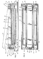
- the connector 90 and connector assembly 91 of the present invention incorporate the principles previously described with respect to FIGS. 1 and 2.
- the ceramic hybrid circuit substrate 85 having the hybrid circuit and its contact surfaces 86 thereon is disposed between a base member 84 and a latch member 92 engageable with the base member 84.
- latch member 92 is shown in an open position, and in solid lines in a closed position engaged to base member 84.
- Base member 84 is adapted to be secured to a cartridge chassis 93 which is disposed within a well-logging tool (not shown).
- Cartridge chassis 93 may normally be made of stainless steel and is provided with screw threads 94 adapted to receive a bolt (not shown) which passes through openings 95 in base member 84, whereby base member 84 is secured to the cartridge chassis 93.
- Base member 84 and latch member 92 may be manufactured of any suitable material ; however, it is preferred that base member 84 be manufactured of an electrically non-conductive plastic material such as a silicone resin/glass powder composite, and latch member 92 may be manufactured of aluminum.
- Base member 84 should have a coefficient of thermal expansion close to that of the cartridge chassis 93. With reference to FIGS. 2 and 3, it should be noted that base member 84 is the same in both figures, and base chassis member 87 of FIG. 2 has latch member 92 substituted therefor in FIG. 3.
- the geometry of the various components, and the previously described formulae and calculations, are likewise applicable to the connector 90 and connector assembly 91 of FIGS. 3 and 4.
- latch member 92 is pivotably mounted to the base member 84 as by a hinge 96 disposed on a first end 97 of latch member 92, and the second end 98 of latch member 92 is provided with a releasable latch 99 which engages the base member 84 as seen in FIG. 3.
- Releasable latch 99 may include a spring-loaded tab 100 which pivots about a pivot pin 101, the lower end of tab 100 being normally biased toward the latch member 84 as by a spring 102.
- the lower end of tab 100 may preferably have a projection 103 formed therein which engages a mating projection 104 disposed on the base member 84 as seen in FIG. 3.
- a plurality of spring-loaded, electrically conductive contact pins 83 are disposed on the base member 84 for supporting and contacting the ceramic hybrid circuit substrate 85 between the base member 84 and the latch member 92, whereby the ceramic hybrid circuit substrate 85 may sufficiently and freely move, without damage thereto, with respect to the base member 84 and latch member 92 as a result of thermal expansion and contraction caused by temperature changes in the borehole, while the ceramic hybrid circuit substrate 85 is sufficiently restrained to prevent damage thereto from shock forces and vibration forces exerted upon the well-logging tool which are imparted to the cartridge chassis 93. Further, the ceramic hybrid circuit substrate 85 and ceramic hybrid circuit contact surfaces 86 will remain in low-resistance electrical contact with the contact pins 83 and the cartridge chassis 93, as previously described and explained with reference to FIG. 2.
- the base member 84 may include means for positioning ceramic hybrid circuit substrate 85 with respect to base member 84 to limit any gross movement of the ceramic hybrid circuit substrate 85 under severe shock and vibration conditions.
- the means for positioning 105 may comprise a recessed support surface 106 which generally conforms to the outer configuration of the ceramic hybrid circuit substrate 85, when the ceramic hybrid circuit substrate 85 has experienced its greatest expansion due to increased temperature conditions in the borehole.
- the recessed support surface 106 is seen in FIG. 4 as including a recessed ledge (shown in dotted lines) extending the length of the two longer sides of the ceramic hybrid circuit substrate 85.
- the plurality of contact pins 83 are disposed in the recessed support surface 106, and the contact pins 83 extend outwardly from the recessed support surface 106 as seen in FIG. 3.
- the forces exerted by the spring-loaded contact pins 83 upon ceramic hybrid circuit substrate 85 and ceramic hybrid circuit contact surfaces 86 are sufficient to make an electrical connection therebetween and to oppose any relative motion between the ceramic hybrid circuit and substrate 85 and the base member 84, when an external shock force is transmitted through the well-logging tool in any direction but particularly a direction perpendicular to the forces exerted by the spring-loaded contact pins 83.
- contact pins 83 have a first end 107 intended for connection to an electrical wiring harness, a plurality of insulated electrical wires, (not shown), so that connections may be made between electrical circuits on the hybrid circuit 85 and other circuits in the well-logging tool.
- the second end 109 of contact pins 83 has a spherical contact surface 89 for contacting the ceramic hybrid circuit contact surfaces 86.
- the structure of the contact pins 83 is shown to include a generally cylindrical housing 110 having a contact member 111 disposed therein for relative movement therebetween.
- Contact member 111 has the spherical contact surface 89 at one end and an enlarged end portion 112 which is restrained from outward movement from housing 110 as by a crimped portion 113 in housing 110.
- a suitable spring 11 4 is captured between the end of housing 110 and the i enlarged end portion 112 of contact member 111.
- f represents the force exerted by spring 114 of contact pin 83
- R represents the radius of curvature of the spherical contact surface 89 of contact member 111
- E represents the elastic modulus for the material of which the spherical contact surface 89 is manufactured
- 86 represents the flat, planar contact surface of the ceramic hybrid circuit and substrate 85.
- the two contact surfaces 89 and 86 are noble-metal surfaces, contact surface 86 preferably being a thick-film gold material disposed on the ceramic hybrid circuit substrate 85.
- contact pins 83 could be associated with the latch member 92 with the first ends 107 of contact pins connected to other circuits in the well-logging tool as by an electrical wiring harness. Ceramic hybrid circuit 85 would then be disposed on base member 84 with the contact surfaces 86 facing upwardly to be engaged by the spherical contact surfaces 89 of the second ends 109 of the contact pins 83, upon latch member 92 being closed as shown in FIG. 3.
- the plotted curve depicts how the peak contact force/unit area rises to a value sufficient to enable the spherical contact surface 89 to pass through any contaminants, particularly all known organic contaminants 116, as seen in FIG. 6, which may be present on the contact surface 86.
- the plotted curve 115 also depicts how the spherical contact surface 89 may be deformed elastically as the contaminants 116 are swept aside, until the force/unit area approaches the elastic limit for the material of which spherical contact surface 89 is manufactured.
- the arrows 117 illustrate the contact area between contact surfaces 89 and 86 due to elastic deformation of the spherical contact surface 89.
- a reliable electrical connection between contact surfaces 89 and 86 may be obtained without the need to plastically deform the contact material of spherical contact surface 89 by correctly choosing the radius R of the spherical contact surface 89, and a material having the requisite elastic modulus E to manufacture the spherical contact surface 89, and a force f resulting from the compression of spring 114.
- the method steps include securing the base member 84 to the cartridge chassis 93, such as by bolts (not shown), which mate with threaded openings 94 in cartridge chassis 93.
- a plurality of spring-loaded, electrically conductive contact pins 83 is then disposed with first end 107 of each contact pin 83 in electrically conductive relationship with a wiring harness (not shown).
- the ceramic hybrid circuit 85 is then placed upon the base member 84 in an overlying relationship to the contact pins 83.
- Latch member 92 is then engaged to the base member 84, as by the latch 99.
- the ceramic hybrid circuit and substrate 85 is then supported between the base member 84 and the latch member 92 by a second end 109 of each contact pin 83.
- the ceramic hybrid circuit and substrate 85 is allowed to sufficiently and freely move, with respect to the base member 84 and the latch member 92, without damage thereto, as a result of thermal expansion and contraction thereof caused by temperature changes in the borehole.
- the ceramic hybrid circuit and substrate 85 is caused to remain in a low-resistance electrical contact with the second end 109 of each contact end 83.
- the contact pins 83 are provided with spherical contact surfaces 89 to contact the ceramic hybrid circuit contact surfaces 86 and a scrubbing action between the contact pins 83 and the ceramic hybrid circuit contact surfaces 86 is prevented.
- the spherical contact surfaces 89 are passed through any organic contaminants 116 on the ceramic hybrid circuit contact surfaces 86.
Landscapes
- Physics & Mathematics (AREA)
- Life Sciences & Earth Sciences (AREA)
- General Life Sciences & Earth Sciences (AREA)
- General Physics & Mathematics (AREA)
- Geophysics (AREA)
- Engineering & Computer Science (AREA)
- Microelectronics & Electronic Packaging (AREA)
- Coupling Device And Connection With Printed Circuit (AREA)
- Connector Housings Or Holding Contact Members (AREA)
- Geophysics And Detection Of Objects (AREA)
- Measurement Of Mechanical Vibrations Or Ultrasonic Waves (AREA)
Applications Claiming Priority (2)
| Application Number | Priority Date | Filing Date | Title |
|---|---|---|---|
| US40359782A | 1982-07-30 | 1982-07-30 | |
| US403597 | 1995-03-14 |
Publications (2)
| Publication Number | Publication Date |
|---|---|
| EP0102875A2 true EP0102875A2 (de) | 1984-03-14 |
| EP0102875A3 EP0102875A3 (de) | 1987-01-21 |
Family
ID=23596353
Family Applications (1)
| Application Number | Title | Priority Date | Filing Date |
|---|---|---|---|
| EP83401553A Withdrawn EP0102875A3 (de) | 1982-07-30 | 1983-07-28 | Verbinder für keramische Hybridschaltungen für Bohrlochuntersuchungsgeräte und Verfahren zum Verbinden von in Bohrlochuntersuchungsgeräten angewendeten keramischen Hybridschaltungen |
Country Status (4)
| Country | Link |
|---|---|
| EP (1) | EP0102875A3 (de) |
| AU (1) | AU567682B2 (de) |
| CA (1) | CA1215744A (de) |
| NO (1) | NO832573L (de) |
Cited By (2)
| Publication number | Priority date | Publication date | Assignee | Title |
|---|---|---|---|---|
| FR2582898A1 (fr) * | 1985-06-04 | 1986-12-05 | Radiotechnique Compelec | Carte pour realiser un systeme de micro-informatique. |
| WO2021112875A1 (en) * | 2019-12-06 | 2021-06-10 | Hewlett-Packard Development Company, L.P. | Installation modules |
Families Citing this family (1)
| Publication number | Priority date | Publication date | Assignee | Title |
|---|---|---|---|---|
| DE102016117331A1 (de) | 2016-09-15 | 2018-03-15 | Knorr-Bremse Systeme für Nutzfahrzeuge GmbH | Gehäusekontaktierung eines Steuergerätes |
Family Cites Families (1)
| Publication number | Priority date | Publication date | Assignee | Title |
|---|---|---|---|---|
| US4341433A (en) * | 1979-05-14 | 1982-07-27 | Amp Incorporated | Active device substrate connector |
-
1983
- 1983-07-15 NO NO832573A patent/NO832573L/no unknown
- 1983-07-28 EP EP83401553A patent/EP0102875A3/de not_active Withdrawn
- 1983-07-29 CA CA000433641A patent/CA1215744A/en not_active Expired
- 1983-07-29 AU AU17448/83A patent/AU567682B2/en not_active Ceased
Cited By (2)
| Publication number | Priority date | Publication date | Assignee | Title |
|---|---|---|---|---|
| FR2582898A1 (fr) * | 1985-06-04 | 1986-12-05 | Radiotechnique Compelec | Carte pour realiser un systeme de micro-informatique. |
| WO2021112875A1 (en) * | 2019-12-06 | 2021-06-10 | Hewlett-Packard Development Company, L.P. | Installation modules |
Also Published As
| Publication number | Publication date |
|---|---|
| EP0102875A3 (de) | 1987-01-21 |
| CA1215744A (en) | 1986-12-23 |
| NO832573L (no) | 1984-01-31 |
| AU1744883A (en) | 1984-02-02 |
| AU567682B2 (en) | 1987-12-03 |
Similar Documents
| Publication | Publication Date | Title |
|---|---|---|
| US4922376A (en) | Spring grid array interconnection for active microelectronic elements | |
| US5931693A (en) | Structure of terminal for coin-shaped battery | |
| US6241531B1 (en) | Compression interconnect system for stacked circuit boards and method | |
| US4218817A (en) | Component mounting apparatus | |
| US4629266A (en) | Electrical device, such as an electrical connector receptacle, for surface mounting on a circuit board | |
| JPS6346993Y2 (de) | ||
| US4632484A (en) | Connector for ceramic hybrid circuits for well-logging tools and method for connecting ceramic hybrid circuits for use in well-logging tools | |
| US20060154527A1 (en) | Contact maker for power semiconductor modules and disc cells | |
| EP0102875A2 (de) | Verbinder für keramische Hybridschaltungen für Bohrlochuntersuchungsgeräte und Verfahren zum Verbinden von in Bohrlochuntersuchungsgeräten angewendeten keramischen Hybridschaltungen | |
| US5999414A (en) | Physically separating printed circuit boards with a resilient, conductive contact | |
| JP2005026683A (ja) | 回路パッケージの支持方法および電子部品システム | |
| US6522518B1 (en) | Reconfigurable multichip module stack interface | |
| JP2001135382A (ja) | 平行基板間接続用電気コネクタ | |
| US6172306B1 (en) | Solder cracking resistant I/O pin connections | |
| KR101976028B1 (ko) | 탄성에 의해 완충작용을 수행하면서 쇼트 발생을 방지할 수 있는 반도체 소켓용 접촉핀 | |
| CN217656085U (zh) | 一种弹性接触高速连接器 | |
| WO2005026679A1 (ja) | 歪検出装置 | |
| JP4815192B2 (ja) | 電気的接続装置 | |
| JPH02226610A (ja) | 異方性導電接着剤およびそれを用いた電子部品の接続方法 | |
| US4831354A (en) | Polymer type PTC assembly | |
| CN114025561A (zh) | 电子设备 | |
| EP3696555A2 (de) | Sondenvorrichtung einer schwimmenden struktur | |
| JP3244621B2 (ja) | 蓄電池の安全装置 | |
| GB2254668A (en) | Mounting of electrical components to printed circuit boards and housings | |
| JP4056584B2 (ja) | 加速度センサ |
Legal Events
| Date | Code | Title | Description |
|---|---|---|---|
| PUAI | Public reference made under article 153(3) epc to a published international application that has entered the european phase |
Free format text: ORIGINAL CODE: 0009012 |
|
| AK | Designated contracting states |
Designated state(s): DE FR GB IT NL |
|
| PUAL | Search report despatched |
Free format text: ORIGINAL CODE: 0009013 |
|
| AK | Designated contracting states |
Kind code of ref document: A3 Designated state(s): DE FR GB IT NL |
|
| STAA | Information on the status of an ep patent application or granted ep patent |
Free format text: STATUS: THE APPLICATION IS DEEMED TO BE WITHDRAWN |
|
| 18D | Application deemed to be withdrawn |
Effective date: 19870203 |
|
| RIN1 | Information on inventor provided before grant (corrected) |
Inventor name: SINCLAIR, PAUL LINCOLN |