EP0102479A2 - Continuous-flow heater for molten metals - Google Patents
Continuous-flow heater for molten metals Download PDFInfo
- Publication number
- EP0102479A2 EP0102479A2 EP83106697A EP83106697A EP0102479A2 EP 0102479 A2 EP0102479 A2 EP 0102479A2 EP 83106697 A EP83106697 A EP 83106697A EP 83106697 A EP83106697 A EP 83106697A EP 0102479 A2 EP0102479 A2 EP 0102479A2
- Authority
- EP
- European Patent Office
- Prior art keywords
- crucible
- furnace
- induction
- melt
- inlet
- Prior art date
- Legal status (The legal status is an assumption and is not a legal conclusion. Google has not performed a legal analysis and makes no representation as to the accuracy of the status listed.)
- Withdrawn
Links
Images
Classifications
-
- H—ELECTRICITY
- H05—ELECTRIC TECHNIQUES NOT OTHERWISE PROVIDED FOR
- H05B—ELECTRIC HEATING; ELECTRIC LIGHT SOURCES NOT OTHERWISE PROVIDED FOR; CIRCUIT ARRANGEMENTS FOR ELECTRIC LIGHT SOURCES, IN GENERAL
- H05B6/00—Heating by electric, magnetic or electromagnetic fields
- H05B6/02—Induction heating
- H05B6/22—Furnaces without an endless core
- H05B6/24—Crucible furnaces
Definitions
- the invention relates to a continuous flow heater for molten metal, e.g. an induction crucible furnace to maintain or increase the temperature level of a molten metal.
- the induction channel furnace is ideal for continuous operation. Batch operation with the induction channel furnace, on the other hand, is difficult for larger units and outputs, since the associated temperature fluctuations, particularly in the refractory lining of the inductors, lead to considerable problems. Accordingly, changing alloys and quality requires considerable effort.
- the induction crucible furnace has already been used for batch heating. Special designs of induction crucible furnaces have also been used for continuous heating.
- a fireproof-lined pipe was fed through the tilting bearing of the induction crucible furnace and was intended to supply the melt to be heated. The discharge took place via an open snout or a siphon by tilting the induction crucible furnace.
- the melt is supplied through a slot in the lid. In both embodiments, it was necessary to change the crucible at shorter intervals than with normal induction crucible furnaces. Significant signs of wear mostly occurred in the areas of the crucible wall.
- the object of the invention is an induction crucible furnace to create, in which the life of the crucible corresponds approximately to the life of the crucible in a normal induction crucible furnace.
- the feed of the melt to the crucible furnace is arranged below the bath level in the furnace.
- One possibility for this is to provide the inlet in the bottom of the crucible.
- the spout can be made through the snout, but it can also be provided in the bottom of the crucible.
- Such an induction crucible furnace with an inlet and outlet in the bottom is particularly suitable if the treatment vessel is also to be placed under vacuum.
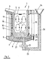
- Fig. 1 shows an induction crucible furnace 1 with a cylindrical crucible 2, which is provided with an inlet 3 for the melt and a pouring spout 4.
- the crucible 2 is filled with melt 5 up to the bath level 6.
- the crucible 2 stands on a refractory base 7, which is supported on a metallic base plate 8.
- the metallic base plate 8 forms with a lower reinforcing ring 9, vertical struts 10 and an upper reinforcing ring 11 the furnace frame.
- the reinforcing ring 11 is shaped in the area of the pouring spout 4 so that the pouring spout 4 can be supported on it.
- the crucible 2 is surrounded by a coil insert 12 and 13. Magnetic yokes 18 ensure the magnetic reflux of the lines of force generated in the active coil.
- clamping devices are arranged, which consist of a lever 19, a threaded spindle 20 and a compression spring 21. With the help of this clamping device, the coils 12 and 13 are pressed against the reinforcing ring 11.
- the bath movement generated by the induction is represented by the lines 22.
- the inlet opening 3 is connected to the connecting pipe 23, which leads to the funnel 24, via flanges 25 or the like.
- a fire-resistant lined pipeline was used for this.
- This pipeline is also provided with thermal insulation 26 in order to avoid heat radiation to the outside or excessive cooling of the melt in the pipeline.
- the static bath pressure in the furnace, which corresponds to the bath level 6, and in the feed line or the funnel 24 must be the same. It is therefore possible to influence the bath level 6 in the furnace via the bath level in the funnel 24.
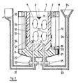
- FIG. 2 shows another embodiment of FIG. 1.
- the outflow opening 30 is arranged here, like the inflow opening 3, in the bottom 27 of the crucible 2.
- This outflow opening 30 is connected to the pouring spout 33 via a connecting line 31, which is connected to the outflow opening via flanges 32.
- a fire-resistant lined pipeline is used is provided on the outside with thermal insulation 34.
- the inlet opening 3 and the outlet opening 30 are close to one another, this does not interfere because the strong stirring effect of the induction current prevents the melt from being directly passed from the inlet to the outlet.
- the corresponding bath movement is also indicated by the lines 22 in this figure.
- the device at the end of the treatment, can be emptied by tilting or, if the induction crucible furnace is not designed to be tiltable, by means of a floor plug, not shown.
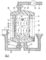
- FIG 3 shows a further embodiment of the invention, in which the crucible 2 is provided with a lid 40 in a vacuum-tight manner and the atmosphere above the bath level 6 can be sucked off through the opening 41 by means of the vacuum pump 43.
- the vacuum pump 43 is connected to the suction opening 41 via the connecting line 42 and the flanges 45.
- At the outlet of the vacuum pump there is a line 44 through which the extracted gases can be discharged.
- This embodiment also has the advantage that the inlet and outlet points 24 and 33 can be deeper than in the embodiment according to FIG. 2. This has the advantage that after treatment, ie after the vacuum has been removed, less residual melt in the treatment unit remains. In addition, of course, are the verb cable lines 46 and 47 shorter.
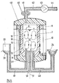
- Fig. 4 shows an embodiment with a one-piece design of the inlet and outlet lines 48 and 49. These are arranged in the part 50, so that a component results.
- This embodiment also has the advantage that the component 50 can be rotated about its vertical and the vertical axis 51 of the crucible furnace, so that the inlet opening 3 and the outlet opening 40 are closed. This component represents a slide.
- the invention is not limited to the exemplary embodiments shown, in particular the inlet can also be designed differently.
Abstract
Durchlauferhitzer für schmelzflüssige Metalle zur Erhaltung bzw. Erhöhung des Temperaturniveaus der Metallschmelze und Erhöhung der Lebensdauer des Tiegels, derart, daß sie in etwa der Lebensdauer des Tiegels bei einem normalen Induktionstiegelofen entspricht, durch Anordnung des Zulaufs der Schmelze zum Tiegelofen unterhalb des Badspiegels im Ofen, z.B. im Boden des Tiegels. Der Ausguß kann über die Schnauze oder auch über einen im Boden des Tiegels vorgeshenen Auslauf erfolgen.Flow heater for molten metals to maintain or increase the temperature level of the metal melt and increase the service life of the crucible in such a way that it roughly corresponds to the service life of the crucible in a normal induction crucible furnace, by arranging the feed of the melt to the crucible furnace below the bath level in the furnace, e.g. in the bottom of the crucible. The pouring can be done through the spout or through an outlet provided in the bottom of the crucible.
Description
Die Erfindung bezieht sich auf einen Durchlauferhitzer für schmelzflüssiges Metall, z.B. einen Induktionstiegelofen zur Erhaltung bzw. Erhöhung des Temperaturniveaus einer Metallschmelze.The invention relates to a continuous flow heater for molten metal, e.g. an induction crucible furnace to maintain or increase the temperature level of a molten metal.
In der Metallurgie ist es oft erforderlich, größere Mengen an schmelzflüssigem Metall von einem Temperaturniveau auf ein höheres Temperaturniveau zu bringen bzw. wenn die erschmolzene Metallmenge nicht sofort abgegossen werden kann, das erreichte Temperaturniveau zu halten. Dies kann entweder im Chargenbetrieb oder kontinuierlich in einem Durchlauferhitzer erfolgen. Grundsätzlich können alle bekannten elektrisch beheizten Schmelzöfen für diesen Zweck benutzt werden.In metallurgy, it is often necessary to bring large amounts of molten metal from a temperature level to a higher temperature level or, if the molten metal amount cannot be poured off immediately, to maintain the temperature level reached. This can be done either in batch mode or continuously in a continuous flow heater. Basically, all known electrically heated melting furnaces can be used for this purpose.
Bei der Verwendung eines Lichtbogenofens für eine chargenweise Erhitzung der Metallschmelze muß jedoch beachtet werden, daß der Wirkungsgrad des Lichtbogenofens für diesen Betrieb sehr gering ist und daß Rückwirkungen auf die zu erhitzende Schmelze auftreten können. Im Fußpunkt des Lichtbogenofens stellen sich sehr hohe Temperaturen ein, die zu einer Verdampfung der Schmelze und damit der Legierungselemente führen sowie eine Stickstoffaufnahme in die Schmelze fördern können. Bei Einsatz von Graphit-Elektroden kann außerdem die Schmelze Kohlenstoff aufnehmen.When using an arc furnace for batch heating of the molten metal, however, it must be noted that the efficiency of the arc furnace for this operation is very low and that there are repercussions on the melt to be heated can. At the base of the arc furnace, very high temperatures occur which lead to evaporation of the melt and thus the alloying elements and can promote nitrogen uptake in the melt. When using graphite electrodes, the melt can also absorb carbon.
Während für chargenweise Erhitzung der Lichtbogenofen anwendbar ist, bietet sich für Durchlaufbetrieb der Induktions-Rinnenofen an. Ein chargenweiser Betrieb mit dem Induktions-Rinnenofen ist dagegen für größere Einheiten und Leistungen schwierig, da die hiermit verbundenen Temperaturschwankungen, insbesondere in der feuerfesten Auskleidung der Induktoren, zu erheblichen Problemen führen. Dementsprechend bedingen Legierungs-und Qualitätswechsel einen beträchtlichen Aufwand.While the arc furnace can be used for batch heating, the induction channel furnace is ideal for continuous operation. Batch operation with the induction channel furnace, on the other hand, is difficult for larger units and outputs, since the associated temperature fluctuations, particularly in the refractory lining of the inductors, lead to considerable problems. Accordingly, changing alloys and quality requires considerable effort.
Um die Nachteile des Lichtbogenofens und des Induktions-Rinnenofens zu vermeiden, ist für eine chargenweise Erhitzung der Induktionstiegelofen bereits eingesetzt worden. Auch für die Erhitzung im Durchlaufbetrieb wurden Induktionstiegelöfen in Sonderbauformen bereits verwendet. Durch das Kipplager des Induktionstiegelofens wurde ein feuerfest ausgekleidetes Rohr geführt, das zur Zuführung der zu erhitzenden Schmelze vorgesehen war. Der Auslauf erfolgte über eine offene oder als Syphon ausgebildete Schnauze durch Kippen des Induktionstiegelofens. Bei einem anderen Induktionstiegelofen erfolgt die Zuführung der Schmelze durch einen im Deckel angebrachten Schlitz. Bei beiden Ausführungsformen war es erforderlich, den Tiegel in kürzeren Abständen als bei normalen Induktionstiegelöfen zu wechseln. Erhebliche Verschleißerscheinungen traten meist an den Bereichen der Tiegelwand auf.In order to avoid the disadvantages of the arc furnace and the induction channel furnace, the induction crucible furnace has already been used for batch heating. Special designs of induction crucible furnaces have also been used for continuous heating. A fireproof-lined pipe was fed through the tilting bearing of the induction crucible furnace and was intended to supply the melt to be heated. The discharge took place via an open snout or a siphon by tilting the induction crucible furnace. In another induction crucible furnace, the melt is supplied through a slot in the lid. In both embodiments, it was necessary to change the crucible at shorter intervals than with normal induction crucible furnaces. Significant signs of wear mostly occurred in the areas of the crucible wall.
Aufgabe der Erfindung ist es, einen Induktionstiegelofen zu schaffen, bei dem die Lebensdauer des Tiegels in etwa der Lebensdauer des Tiegels bei einem normalen Induktionstiegelofen entspricht.The object of the invention is an induction crucible furnace to create, in which the life of the crucible corresponds approximately to the life of the crucible in a normal induction crucible furnace.
Diese Aufgabe wird gemäß der Erfindung dadurch gelöst, daß der Zulauf der Schmelze zum Tiegelofen unterhalb des Badspiegels im Ofen angeordnet ist. Eine Möglichkeit hierzu ist, den Zulauf im Boden des Tiegels vorzusehen. Der Ausguß kann über die Schnauze erfolgen, er kann aber auch im Boden des Tiegels vorgesehen werden. Ein derartiger Induktionstiegelofen mit Zu- und Auslauf im Boden ist besonders geeignet, wenn das Behandlungsgefäß zusätzlich unter Vakuum gesetzt werden soll.This object is achieved according to the invention in that the feed of the melt to the crucible furnace is arranged below the bath level in the furnace. One possibility for this is to provide the inlet in the bottom of the crucible. The spout can be made through the snout, but it can also be provided in the bottom of the crucible. Such an induction crucible furnace with an inlet and outlet in the bottom is particularly suitable if the treatment vessel is also to be placed under vacuum.
Schematische Ausführungsbeispiele der Erfindung sind in den Figuren 1 bis 4 dargestellt.Schematic exemplary embodiments of the invention are shown in FIGS. 1 to 4.
Es zeigen:
- Fig. 1 einen Induktionstiegelofen mit Schmelzenzulauf im Boden und Ausguß durch eine Gießsohnauze;
- Fig. 2 einen Induktionstiegelofen mit Zu- und Ablauf im Boden;
- Fig. 3 eine vakuumdichte Ausführungsform der
Figur 2 mit einer Vakuumpumpe zum Absaugen der Atmosphäre über dem Badspiegel; - Fig. 4 eine Variante der Fig. 3, bei der Ein- und Auslauf eine Baueinheit bilden und als Verschlußschieber benutzt werden können.
- Figure 1 shows an induction crucible furnace with melt inlet in the bottom and pouring through a Gießsohnauze.
- 2 shows an induction crucible furnace with inlet and outlet in the bottom;
- 3 shows a vacuum-tight embodiment of FIG. 2 with a vacuum pump for suctioning off the atmosphere above the bath level;
- Fig. 4 shows a variant of Fig. 3, in which the inlet and outlet form a structural unit and can be used as a slide valve.
Fig. 1 zeigt einen Induktionstiegelofen 1 mit einem zylindrischen Tiegel 2, der mit einem Einlaß 3 für die Schmelze und einer Gießschnauze 4 versehen ist. Der Tiegel 2 ist mit Schmelze 5 bis zum Badspiegel 6 gefüllt. Der Tiegel 2 steht auf einem feuerfesten Boden 7, der sich auf einer metallischen Bodenplatte 8 abstützt. Die metallische Bodenplatte 8 bildet mit einem unteren Verstärkungsring 9, senkrechten Streben 10 und einem oberen Verstärkungsring 11 das Ofengestell. Der Verstärkungsring 11 ist im Bereich der Gießschnauze 4 so geformt, daß sich die Gießschnauze 4 auf ihm abstützen kann. Der Tiegel 2 ist von einem Spuleneinsatz 12 und 13 umgeben. Magnetjoche 18 stellen den magnetischen Rückfluß der in der aktiven Spule erzeugten Kraftlinien sicher.Fig. 1 shows an
Am unteren Ende des Spuleneinsatzes sind Spannvorrichtungen angeordnet, die aus einem Hebel 19, einer Gewindespindel 20 sowie einer Druckfeder 21 bestehen. Mit Hilfe dieser Spannvorrichtung werden die Spulen 12 und 13 gegen den Verstärkungsring 11 gepreßt.At the lower end of the coil insert, clamping devices are arranged, which consist of a
Die durch die Induktion erzeugte Badbewegung ist durch die Linien 22 dargestellt. Die Einlauföffnung 3 ist mit dem Verbindungsrohr 23, das zu dem Trichter 24 führt, über Flansche 25 oder dergl. verbunden. Hierfür ist eine feuerfest ausgekleidete Rohrleitung benutzt worden. Diese Rohrleitung ist außerdem mit einer Wärmeisolierung 26 versehen, um eine Wärmeabstrahlung nach außen bzw. eine zu starke Abkühlung der in der Rohrleitung befindlichen Schmelze zu vermeiden. Der statische Baddruck im Ofen, der dem Badspiegel 6 entspricht, und in der Zulaufleitung bzw. dem Trichter 24 müssen gleich sein. Es ist daher möglich, über den Badspiegel im Trichter 24 den Badspiegel 6 im Ofen zu beeinflussen.The bath movement generated by the induction is represented by the
Fig. 2 zeigt eine andere Ausführungsform der Fig. 1. Die Ausflußöffnung 30 ist hier ebenso wie die Zuflußöffnung 3 im Boden 27 des Tiegels 2 angeordnet. Über eine Verbindungsleitung 31, die über Flansche 32 mit der Ausflußöffnung verbunden ist, ist diese Ausflußöffnung 30 mit der Ausgießschnauze 33 verbunden. Auch hier wird eine feuerfest ausgekleidete Rohrleitung verwendet, die nach außen mit einer Wärmeisolierung 34 versehen ist. Trotzdem die Zulauföffnung 3 und die Auslauföffnung 30 nahe beieinanderliegen, stört dies nicht, da durch die starke Rührwirkung des Induktionsstromes ein direktes Übertreten der Schmelze vom Zulauf zum Auslauf verhindert wird. Auch in dieser Figur ist die entsprechende Badbewegung durch die Linien 22 angedeutet.FIG. 2 shows another embodiment of FIG. 1. The outflow opening 30 is arranged here, like the inflow opening 3, in the
Bei den in Fig. 1 und 2 dargestellten Ausführungsformen kann am Ende der Behandlung die Vorrichtung durch Kippen oder, falls der Induktionstiegelofen nicht kippbar ausgeführt ist, über einen nicht dargestellten Bodenstopfen entleert werden.In the embodiments shown in FIGS. 1 and 2, at the end of the treatment, the device can be emptied by tilting or, if the induction crucible furnace is not designed to be tiltable, by means of a floor plug, not shown.
Die Fig. 3 zeigt eine weitere Ausführungsform der Erfindung, bei der der Tiegel 2 mit einem Deckel 40 vakuumdicht versehen ist und die Atmosphäre oberhalb des Badspiegels 6 durch die Öffnung 41 mittels der Vakuumpumpe 43 abgesaugt werden kann. Die Vakuumpumpe 43 ist mit der Absaugöffnung 41 über die Verbindungsleitung 42 und die Flansche 45 verbunden. Am Ausgang der Vakuumpumpe befindet sich eine Leitung 44, über die die abgesaugten Gase abgeführt werden können. Mit dieser Anordnung ist es möglich, gleichzeitig mit der Erhitzung eine Vakuumbehandlung zu verbinden. Sie ist besonders zweckmäßig, da infolge der bereits erwähnten starken Badbewegungen im Induktionstiegelofen praktisch alle Teile der Schmelze an die Badoberfläche gespült und somit direkt der Wirkung des Vakuums ausgesetzt werden.3 shows a further embodiment of the invention, in which the
Außerdem hat diese Ausführung noch den Vorteil, daß die Ein- und Auslaufstellen 24 und 33 tiefer sein können, als bei der Ausführungsform nach Fig. 2. Dies hat den Vorteil, daß nach einer Behandlung, d.h. nach Wegnehmen des Vakuums weniger Restschmelze in der Behandlungseinheit zurückbleibt. Außerdem sind natürlich die Verbindungsleitungen 46 und 47 kürzer.This embodiment also has the advantage that the inlet and
Die Fig. 4 zeigt eine Ausführungsform mit einer einstückigen Ausführung der Zu- und Abflußleitungen 48 und 49. Diese sind in dem Teil 50 angeordnet, so daß sich ein Bauteil ergibt. Diese Ausführungsform hat noch den Vorteil, daß das Bauteil 50 um seine vertikale und die vertikale Achse 51 des Tiegelofens verdreht werden kann, so daß die Zuflußöffnung 3 und die Abflußöffnung 40 abgeschlossen werden. Dieses Bauteil stellt einen Schieber dar.Fig. 4 shows an embodiment with a one-piece design of the inlet and
Die Erfindung ist nicht auf die dargestellten Ausführungsbeispiele beschränkt, insbesondere kann der Zulauf auch anders ausgeführt sein.The invention is not limited to the exemplary embodiments shown, in particular the inlet can also be designed differently.
Claims (4)
Applications Claiming Priority (2)
| Application Number | Priority Date | Filing Date | Title |
|---|---|---|---|
| DE19823229367 DE3229367A1 (en) | 1982-08-06 | 1982-08-06 | CONTINUOUS HEATER FOR MELT-LIQUID METALS |
| DE3229367 | 1982-08-06 |
Publications (2)
| Publication Number | Publication Date |
|---|---|
| EP0102479A2 true EP0102479A2 (en) | 1984-03-14 |
| EP0102479A3 EP0102479A3 (en) | 1984-09-05 |
Family
ID=6170276
Family Applications (1)
| Application Number | Title | Priority Date | Filing Date |
|---|---|---|---|
| EP83106697A Withdrawn EP0102479A3 (en) | 1982-08-06 | 1983-07-08 | Continuous-flow heater for molten metals |
Country Status (4)
| Country | Link |
|---|---|
| US (1) | US4486889A (en) |
| EP (1) | EP0102479A3 (en) |
| JP (1) | JPS5944574A (en) |
| DE (1) | DE3229367A1 (en) |
Families Citing this family (6)
| Publication number | Priority date | Publication date | Assignee | Title |
|---|---|---|---|---|
| JPH0579769A (en) * | 1991-09-20 | 1993-03-30 | Fuji Electric Co Ltd | High-speed melting induction furnace with weighty lid |
| US6393044B1 (en) * | 1999-11-12 | 2002-05-21 | Inductotherm Corp. | High efficiency induction melting system |
| US20050098294A1 (en) * | 2003-11-12 | 2005-05-12 | Howard Robert W. | Casting device and method |
| US7413590B2 (en) * | 2006-01-11 | 2008-08-19 | Heritage Environmental Services, Llc | Use of an induction furnace for the production of iron from ore |
| US20080130704A1 (en) * | 2006-11-30 | 2008-06-05 | Lapoint Albert E | Electroslag smelting system and method |
| GB2586634B (en) * | 2019-08-30 | 2022-04-20 | Dyson Technology Ltd | Multizone crucible apparatus |
Citations (2)
| Publication number | Priority date | Publication date | Assignee | Title |
|---|---|---|---|---|
| US3320348A (en) * | 1964-08-07 | 1967-05-16 | V & V Companies Inc | Induction melting furnace |
| US3700779A (en) * | 1970-07-30 | 1972-10-24 | Est Aciers Fins | Method of treatment of liquid steel under vacuum |
Family Cites Families (4)
| Publication number | Priority date | Publication date | Assignee | Title |
|---|---|---|---|---|
| DE1061003B (en) * | 1958-04-12 | 1959-07-09 | Otto Junker Fa | Coreless induction melting furnace for vacuum operation |
| US3230073A (en) * | 1962-07-20 | 1966-01-18 | Asea Ab | Process for vacuum degassing with electromagnetic stirring |
| US3380511A (en) * | 1964-05-25 | 1968-04-30 | Campbell James Samuel | Apparatus for automatically filling a receptacle |
| US3819842A (en) * | 1972-04-24 | 1974-06-25 | Elin Union Ag | Method and furnace for maintaining the temperature level of metal melts |
-
1982
- 1982-08-06 DE DE19823229367 patent/DE3229367A1/en not_active Withdrawn
-
1983
- 1983-07-08 EP EP83106697A patent/EP0102479A3/en not_active Withdrawn
- 1983-08-01 US US06/519,096 patent/US4486889A/en not_active Expired - Fee Related
- 1983-08-05 JP JP58142630A patent/JPS5944574A/en active Pending
Patent Citations (2)
| Publication number | Priority date | Publication date | Assignee | Title |
|---|---|---|---|---|
| US3320348A (en) * | 1964-08-07 | 1967-05-16 | V & V Companies Inc | Induction melting furnace |
| US3700779A (en) * | 1970-07-30 | 1972-10-24 | Est Aciers Fins | Method of treatment of liquid steel under vacuum |
Also Published As
| Publication number | Publication date |
|---|---|
| JPS5944574A (en) | 1984-03-13 |
| US4486889A (en) | 1984-12-04 |
| DE3229367A1 (en) | 1984-02-09 |
| EP0102479A3 (en) | 1984-09-05 |
Similar Documents
| Publication | Publication Date | Title |
|---|---|---|
| EP0193948B1 (en) | Device and process for keeping molten metals warm | |
| EP1152854A1 (en) | Method and device for producing cast parts consisting of aluminium and magnesium alloys | |
| EP0133925A1 (en) | Bottom electrode arrangement for a direct current arc furnace | |
| EP0102479A2 (en) | Continuous-flow heater for molten metals | |
| EP1006205B1 (en) | Process for the manufacture of homogenous alloys by melting and remelting | |
| EP1140391B1 (en) | Method and device for controlling and/or maintaining the temperature of a melt, preferably of a steel melt during continuous casting | |
| DE1433406B2 (en) | Arrangement for degassing steel or metal melts | |
| EP0133931B1 (en) | Cooling arrangement of a bottom electrode of a direct current arc furnace | |
| DE1960283A1 (en) | Vacuum degassing apparatus for use in continuous casting of metals and methods of continuously casting molten metal while it is being vacuum degassed | |
| DE2724489C2 (en) | Metal melting furnace | |
| DE2501603C3 (en) | ||
| EP1450974B1 (en) | Device consisting of a heatable casting vessel and a ladle furnace | |
| AT204711B (en) | Furnace for melting and casting under vacuum or inert gas atmosphere | |
| DE2147548A1 (en) | Process for refining and casting steel and an arrangement for carrying out the process | |
| DE4129756C2 (en) | Metallurgical vessel for a DC arc device | |
| DE593834C (en) | Process for the vacuum treatment of metals and alloys with melting points above 1200íÒ | |
| DE1458804B1 (en) | Device for degassing melts under vacuum | |
| DE3637065A1 (en) | Ladle with heating device | |
| DE1458804C (en) | Device for degassing melts under vacuum | |
| DE7922196U1 (en) | DEVICE FOR HEATING A WATERING PAN | |
| DE647114C (en) | Device for the production of dense cast blocks | |
| DE2648433A1 (en) | IMPROVEMENT OF CASTING AND CONTINUOUS CASTING INDUCTION FURNACES AND TREATMENT PANS | |
| DE269069C (en) | ||
| DE1143606B (en) | System for melting and casting metals or alloys under vacuum or protective gas | |
| DE1925484A1 (en) | Refining metals |
Legal Events
| Date | Code | Title | Description |
|---|---|---|---|
| PUAI | Public reference made under article 153(3) epc to a published international application that has entered the european phase |
Free format text: ORIGINAL CODE: 0009012 |
|
| AK | Designated contracting states |
Designated state(s): AT BE FR NL SE |
|
| PUAL | Search report despatched |
Free format text: ORIGINAL CODE: 0009013 |
|
| AK | Designated contracting states |
Designated state(s): AT BE FR NL SE |
|
| STAA | Information on the status of an ep patent application or granted ep patent |
Free format text: STATUS: THE APPLICATION IS DEEMED TO BE WITHDRAWN |
|
| 18D | Application deemed to be withdrawn |
Effective date: 19850507 |
|
| RIN1 | Information on inventor provided before grant (corrected) |
Inventor name: DOETSCH, ERWIN, DR., DIPL.-ING. Inventor name: HEGEWALDT, FRITZ, DIPL.-ING. |