EP0102282A2 - Verfahren und Einrichtung zum Dosieren von kleinen Gehalten von gasförmigen Bestandteilen - Google Patents
Verfahren und Einrichtung zum Dosieren von kleinen Gehalten von gasförmigen Bestandteilen Download PDFInfo
- Publication number
- EP0102282A2 EP0102282A2 EP83401604A EP83401604A EP0102282A2 EP 0102282 A2 EP0102282 A2 EP 0102282A2 EP 83401604 A EP83401604 A EP 83401604A EP 83401604 A EP83401604 A EP 83401604A EP 0102282 A2 EP0102282 A2 EP 0102282A2
- Authority
- EP
- European Patent Office
- Prior art keywords
- component
- radiation
- mixture
- tank
- diaphragm
- Prior art date
- Legal status (The legal status is an assumption and is not a legal conclusion. Google has not performed a legal analysis and makes no representation as to the accuracy of the status listed.)
- Granted
Links
Images

Classifications
-
- G—PHYSICS
- G01—MEASURING; TESTING
- G01J—MEASUREMENT OF INTENSITY, VELOCITY, SPECTRAL CONTENT, POLARISATION, PHASE OR PULSE CHARACTERISTICS OF INFRARED, VISIBLE OR ULTRAVIOLET LIGHT; COLORIMETRY; RADIATION PYROMETRY
- G01J1/00—Photometry, e.g. photographic exposure meter
- G01J1/10—Photometry, e.g. photographic exposure meter by comparison with reference light or electric value provisionally void
- G01J1/20—Photometry, e.g. photographic exposure meter by comparison with reference light or electric value provisionally void intensity of the measured or reference value being varied to equalise their effects at the detectors, e.g. by varying incidence angle
- G01J1/34—Photometry, e.g. photographic exposure meter by comparison with reference light or electric value provisionally void intensity of the measured or reference value being varied to equalise their effects at the detectors, e.g. by varying incidence angle using separate light paths used alternately or sequentially, e.g. flicker
- G01J1/36—Photometry, e.g. photographic exposure meter by comparison with reference light or electric value provisionally void intensity of the measured or reference value being varied to equalise their effects at the detectors, e.g. by varying incidence angle using separate light paths used alternately or sequentially, e.g. flicker using electric radiation detectors
-
- G—PHYSICS
- G01—MEASURING; TESTING
- G01N—INVESTIGATING OR ANALYSING MATERIALS BY DETERMINING THEIR CHEMICAL OR PHYSICAL PROPERTIES
- G01N21/00—Investigating or analysing materials by the use of optical means, i.e. using sub-millimetre waves, infrared, visible or ultraviolet light
- G01N21/17—Systems in which incident light is modified in accordance with the properties of the material investigated
- G01N21/25—Colour; Spectral properties, i.e. comparison of effect of material on the light at two or more different wavelengths or wavelength bands
- G01N21/31—Investigating relative effect of material at wavelengths characteristic of specific elements or molecules, e.g. atomic absorption spectrometry
- G01N21/314—Investigating relative effect of material at wavelengths characteristic of specific elements or molecules, e.g. atomic absorption spectrometry with comparison of measurements at specific and non-specific wavelengths
Definitions
- the present invention relates to the metering of a component present at low content in a gaseous mixture by absorption of radiation characteristic of this component.
- gaseous should be interpreted broadly to mean just as well a vapor or dispersion as a gas proper.
- the present invention aims to provide a method and a dosing device of the above defined type which responds better than previous systems to the requirements of practice, in particular by the association of a simple constitution and a satisfactory sensitivity.
- the invention also aims to provide a simple solution to the problem of the selectivity of the measurement in the case where absorption lines belonging to parasitic gases are superimposed on those of the gaseous component whose content is to be determined.
- the invention aims to eliminate the incidence of a possible polarization of the beam which crosses the mixture.
- the invention proposes in particular a method of the kind defined above, characterized in that the second path traversed by the radiation beam is limited to a diaphragm having a transmission of radiation substantially equal to that of the first path in the absence of said component in the mixture and in that the output beam from the two channels is directed towards a detector of variations in intensity of the beam, through a filter for selecting said characteristic radiation.
- the invention also provides a device for metering a component present at low content in a gaseous mixture, comprising means for alternately directing a beam of radiation containing the characteristic radiation of the component, according to a first path which comprises a volume of said component, and a second channel comprising a diaphragm calibrated so as to have a transmission substantially equal to that of the first channel when the mixture does not contain said component, as well as means for directing the beams coming from the two channels, through a filter transmitting a determined fraction of the absorption spectral band of the component to be detected, to a detector associated with means for measuring variations in the detector output signal.
- the incident radiation beam can be constituted by natural light.
- a light source adapted to the spectral range of the characteristic radiation will more often be used, which may, depending on the case, be in the ultraviolet, visible or infrared (the latter case excluding the use of natural light).
- the elements defined above can be grouped together in the same device, but the emission of the source through the atmospheric zone where the measurement is made is then returned by a directional reflector placed at a distance, for example by a reflector which eliminates the pointing problems of the reflector.
- the method according to the invention uses the modulation of the signal supplied by an electro-optical detector which receives a light beam having passed through the mixture containing a component to be assayed, alternately in two ways.
- the beam On one of the channels, the beam, which has already undergone a weakening ⁇ (u 1 ) when crossing the mixture, passes through a diaphragm which limits the cross section of the beam, which results in a transmission coefficient k.
- the same beam passes through a tank containing a well-determined quantity of the gas to be metered, possibly mixed with another gas having no absorption band covering that of the gaseous component to be detected.
- This tank has a transmission coefficient T (u 2 ) depending on the quantity u 2 of gas it contains. 1
- the quantity of gaseous compound absorbing the radiation is indicated by its pressure, (possibly its partial pressure) in the tank, of determined volume.
- the beams leaving the diaphragm and the tank are alternately supplied to the detector, preceded by a filter centered on the absorption band of the gaseous component to be assayed.
- the spectral composition of the beam which crosses the mixture to be assayed, then travels through one or the other of the two paths to the detector, is chosen according to the spectral absorption band.
- a signal modulation appears when an amount of gas (u 1 ) is in the optical path upstream of the two channels.
- the amplitude of this modulation is proportional to the quantity of gas traversed and it also depends on the derivative d T / of the measured for the values u 0 and u 2 .
- u 2 has been chosen to correspond to a transmission coefficient of 70%.
- the modulation rate obtained will be:
- (d ⁇ / du) uO designates the slope of the variation curve at the origin, that is to say for a transmission coefficient equal to 1. As it is in practice not possible to measure the slope at this point, we measure it nearby. For example, in Figures 1A and 1B, the slope is measured for a value of u 0 which corresponds to a transmission coefficient between 0.9 and 1.
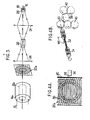
- the device shown in FIG. 2 can be used.
- This device comprises advantageously an artificial source of radiation not shown.
- the device includes two parallel tracks.
- the first consists of a sealed tub 12 of tubular shape, closed by portholes transparent to the radiation used for the measurement.
- the tank 12 contains an amount of the gaseous component to be detected at 11 chosen so that its transmission coefficient is between 0.5 and 0.7.
- the length of the tank will naturally depend on the average intensity of the absorption and it will be possible to bring the pressure in the tank to a value close to atmospheric pressure by adding a gas having no absorption band having a covering with the strip in which the measurement is made, for example with dry nitrogen.
- the other channel is constituted by a circular diaphragm 14J with a transmission coefficient k, the axis of which is parallel to that of the tank.
- Means placed upstream or downstream of the tank 12 and the diaphragm 14 allow a detector 16 to receive alternately, through a filter 18, the light having followed one or the other of the two paths.
- These means are constituted by an optical modulator 20 in a half moon, driven by a rotation movement at constant speed around its axis, as indicated by the arrow f. When it rotates, this modulator alternately closes the two channels and lets the incident radiation pass progressively from one channel to another.
- the device shown in Figure 2 further comprises a tank 22 and an optical system (lenses 24 or mirrors) passing all of the light from one and the other of the channels through the tank.
- This is intended to receive a well-defined quantity of parasitic gases likely to be found in zone 11 at the same time as the gas whose content is to be measured.
- This tank providing identical absorption on the two ways, considerably increases the selectivity of the measurement by limiting the effects of a variation in the content of parasitic gases in the-zone 11.
- the device may also include a calibration system constituted by a barrel carrying several small tanks 26, near the detector 16. By rotation of the barrel, these tanks can be brought successively, which contain known and different quantities of the gas to be detected and to be dosed, on the common optical path, and thus calibrate the device.
- One of the tanks is empty to allow zeroing by compensating for losses due to absorption by the portholes.
- a small adjustable flap allows you to exactly equalize the values of the transmissions by the two channels.
- the device of Figure 2 has the disadvantage of being sensitive to the possible polarization of light, when it comes from the sky. This defect can be significantly reduced by interposing on the two channels, before the input lens 24, a depolarizing plate, transparent in the spectral range used.
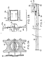
- this drawback is eliminated in the embodiment shown in FIG. 3 where the diaphragm 14a is constituted by an annular opening, delimited by a tube concentric with the tank. -This tube can also be used as a sun visor by extending it outwards.
- FIGS. 4 and 5 show two variants adaptable to the case of an annular diaphragm.
- the modulator 20a shown in FIGS. 4A and 48 comprises a curtain of lamellae 30 rotating around parallel axes.
- the first two and last slats (vertically) are entirely located on the first track. They are therefore in a single section.
- the intermediate lamellae for example the four middle blades, one of which is shown in FIG. 4B, have a central section 32 and two lateral sections 34, at 90 ° from the section 32 so that the beam directed towards the tank is completely stopped when the beam passing through the diaphragm is free, and vice versa.
- a motor 36 can be coupled to a central pinion 38 which controls two sets of pinions 40 each associated with a strip.
- FIG. 5 A simpler solution than that of FIGS. 4A and 4B, but on the other hand more bulky, is shown in FIG. 5.
- the means for orienting alternately the radiation through the tank 12a and through the diaphragm 14a are constituted by a central disc 42 rotating around an axis perpendicular to that of the tank, and two external plates 44 rotating around axes parallel to the previous one.
- the opaque central disc has an area equal to the useful area of the inlet porthole of the tank 12a. It is rotated at constant speed by a motor not shown.
- the two external plates 44 are synchronized in rotation with the central disc 42, for example by a gear train 46, and are in the same plane when the disc 42 presents its edge to the incident radiation.
- the plates 44 are cut so as to completely interrupt the passage of a beam through the diaphragm 14a and to completely free the passage of the radiation towards the tank 12a when they are in the same plane, as indicated in FIG. 5B.
- the device is completed by a circuit for measuring the modulation of the output signal of the detector 16.
- This circuit can be similar to that described in patent FR-A-2 181 203; such a circuit is shown diagrammatically in FIG. 2. It includes an amplifier 48 having a bandwidth compatible with the frequency fixed by the means of alternating orientation of the radiation (modulator disk 20 in FIG. 2).
- the amplifier 48 drives a synchronous detector 50 which receives a reference signal, for example from a sensor 52 associated with the disk 20.
- This output signal from the detector 50 can be displayed or supplied to a recorder 54, for example on strip of paper.
- the source of radiation is chosen according to the nature of the gas to be measured. It is convenient to use the sky when the measurements can be made in ultraviolet or in the visible and are planned only during the day.
- the effect of polarization and absorption by clouds, fumes and index variations can be greatly reduced by using the concentric arrangement shown in Figure 3.
- the reflecting device will advantageously be a reflector to make the problem of orientation of the device and of the stability in _case of vibration disappear.
- the source 58 is associated with a collimating mirror 60 which provides a parallel beam, returned by reflecting trihedrons 62 at a distance which can be several hundreds of meters.
- the radiation flux 10 which crosses twice the area to be studied 11 (which increases the sensitivity) is taken up by the means intended to orient the radiation alternately towards one or the other of the two channels, then by an optical system. , for example catadioptric, of concentration on the detector 16.
- the device thus produced makes it possible to obtain a high sensitivity, greater than that of the device described in the earlier patent already mentioned, while retaining a high selectivity, especially when places on the common path of the beams a tank containing a determined quantity of any parasitic gases.
Landscapes
- Physics & Mathematics (AREA)
- Spectroscopy & Molecular Physics (AREA)
- General Physics & Mathematics (AREA)
- Health & Medical Sciences (AREA)
- Life Sciences & Earth Sciences (AREA)
- Chemical & Material Sciences (AREA)
- Analytical Chemistry (AREA)
- Biochemistry (AREA)
- General Health & Medical Sciences (AREA)
- Immunology (AREA)
- Pathology (AREA)
- Investigating Or Analysing Materials By Optical Means (AREA)
Applications Claiming Priority (2)
| Application Number | Priority Date | Filing Date | Title |
|---|---|---|---|
| FR8213551A FR2531535B1 (fr) | 1982-08-03 | 1982-08-03 | Procede et dispositif de dosage de faible teneur de composants gazeux |
| FR8213551 | 1982-08-03 |
Publications (3)
| Publication Number | Publication Date |
|---|---|
| EP0102282A2 true EP0102282A2 (de) | 1984-03-07 |
| EP0102282A3 EP0102282A3 (en) | 1985-01-30 |
| EP0102282B1 EP0102282B1 (de) | 1987-04-01 |
Family
ID=9276587
Family Applications (1)
| Application Number | Title | Priority Date | Filing Date |
|---|---|---|---|
| EP83401604A Expired EP0102282B1 (de) | 1982-08-03 | 1983-08-02 | Verfahren und Einrichtung zum Dosieren von kleinen Gehalten von gasförmigen Bestandteilen |
Country Status (4)
| Country | Link |
|---|---|
| US (1) | US4579456A (de) |
| EP (1) | EP0102282B1 (de) |
| DE (1) | DE3370689D1 (de) |
| FR (1) | FR2531535B1 (de) |
Cited By (2)
| Publication number | Priority date | Publication date | Assignee | Title |
|---|---|---|---|---|
| WO1986001295A1 (en) * | 1984-08-10 | 1986-02-27 | Boliden Aktiebolag | Gas correlation lidar |
| EP0267956A4 (de) * | 1986-05-30 | 1990-01-08 | Diffracto Ltd | Defraktionsindexabbildung. |
Families Citing this family (2)
| Publication number | Priority date | Publication date | Assignee | Title |
|---|---|---|---|---|
| IT1191378B (it) * | 1985-03-29 | 1988-03-23 | Walterscheid Gmbh Jean | Dispositivo a scatto per il collegamento dell'albero della presa di forza di una trattrice con l'albero cardanico azionante una macchina operatrice |
| FR2772127B1 (fr) * | 1997-12-05 | 2000-02-18 | Oldham France Sa | Procede de determination de la concentration d'un gaz dans un melange gazeux et dispositif d'analyse pour la mise en oeuvre d'un tel procede |
Family Cites Families (19)
| Publication number | Priority date | Publication date | Assignee | Title |
|---|---|---|---|---|
| US3049962A (en) * | 1955-10-03 | 1962-08-21 | Baulio Ets | Method and apparatus for eliminating the dazzling effect of strong sources of light, particularly for automotive vehicles |
| GB847440A (en) * | 1957-05-02 | 1960-09-07 | Optische Ind De Oude Delft Nv | "improvements relating to photographic mirror-objective cameras provided with diaphragms" |
| US3137757A (en) * | 1958-02-07 | 1964-06-16 | Parsons & Co Sir Howard G | Apparatus for the analysis of substances by absorption of radiation |
| US3038083A (en) * | 1959-12-18 | 1962-06-05 | Dejur Amsco Corp | Adjustable light baffle |
| DE1208180B (de) * | 1962-05-24 | 1965-12-30 | Beckman & Whitley Inc | Schnell arbeitende Verschlussvorrichtung |
| US3279308A (en) * | 1963-12-02 | 1966-10-18 | Dow Chemical Co | Dispersive analyzer having means for segregating different wavelengths of radiation from a single source |
| DE1572900B1 (de) * | 1967-06-21 | 1970-01-15 | Zeiss Carl Fa | Spektrometer |
| US3488491A (en) * | 1967-07-31 | 1970-01-06 | Melpar Inc | Filter techniques for gas analyzers employing an inert gas to pressure broaden the absorption spectrum of gas being detected |
| DE2045386C3 (de) * | 1970-08-07 | 1980-04-03 | Nils Dr.Med. 8035 Gauting Kaiser | Gerät zur Bestimmung des CO2 -Gehaltes einer biologischen Substanz |
| US3790797A (en) * | 1971-09-07 | 1974-02-05 | S Sternberg | Method and system for the infrared analysis of gases |
| US3869613A (en) * | 1972-02-01 | 1975-03-04 | Akron Scient Labs | Infrared gas analyzers |
| DE2211073A1 (de) * | 1972-03-08 | 1973-09-13 | Bosch Gmbh Robert | Truebungsmessgeraet |
| FR2181203A5 (de) * | 1972-04-21 | 1973-11-30 | Onera (Off Nat Aerospatiale) | |
| US3811776A (en) * | 1973-02-26 | 1974-05-21 | Environmental Res & Tech | Gas analyzer |
| US3976883A (en) * | 1973-05-10 | 1976-08-24 | Honeywell Inc. | Infrared analyzer |
| US3976884A (en) * | 1974-12-31 | 1976-08-24 | Science Applications, Inc. | Method for remote monitoring of gaseous products |
| US4004146A (en) * | 1975-04-15 | 1977-01-18 | H. Maihak A.G. | Infrared gas analyzing photometer with chopper designed to avoid radiation waste |
| JPS5399985A (en) * | 1977-02-12 | 1978-08-31 | Horiba Ltd | Optical system apparatus |
| US4288693A (en) * | 1978-06-22 | 1981-09-08 | Hartmann & Braun Aktiengesellschaft | Nondispersive infrared gas analyzer |
-
1982
- 1982-08-03 FR FR8213551A patent/FR2531535B1/fr not_active Expired
-
1983
- 1983-08-02 DE DE8383401604T patent/DE3370689D1/de not_active Expired
- 1983-08-02 EP EP83401604A patent/EP0102282B1/de not_active Expired
- 1983-08-03 US US06/519,929 patent/US4579456A/en not_active Expired - Fee Related
Cited By (2)
| Publication number | Priority date | Publication date | Assignee | Title |
|---|---|---|---|---|
| WO1986001295A1 (en) * | 1984-08-10 | 1986-02-27 | Boliden Aktiebolag | Gas correlation lidar |
| EP0267956A4 (de) * | 1986-05-30 | 1990-01-08 | Diffracto Ltd | Defraktionsindexabbildung. |
Also Published As
| Publication number | Publication date |
|---|---|
| FR2531535A1 (fr) | 1984-02-10 |
| DE3370689D1 (en) | 1987-05-07 |
| EP0102282B1 (de) | 1987-04-01 |
| US4579456A (en) | 1986-04-01 |
| FR2531535B1 (fr) | 1985-08-30 |
| EP0102282A3 (en) | 1985-01-30 |
Similar Documents
| Publication | Publication Date | Title |
|---|---|---|
| EP0015170B1 (de) | Spektrofotometrische Vorrichtung mit Fernmessung | |
| EP1183518B1 (de) | Vorrichtung zur bestimmung der werte mindestens eines teilchenparameters, insbesondere von wassertröpfchen | |
| FR2761779A1 (fr) | Dispositif de mesure d'absorption d'infrarouge | |
| FR2782164A1 (fr) | Detecteur de gaz optique a infrarouge | |
| EP3884268A1 (de) | Sonde zur messung der zusammensetzung eines oxidierenden gases | |
| FR2541460A1 (fr) | Procede et appareil pour la detection et le comptage de particules presentes dans une suspension en circulation, pour analyses hematologiques et autres | |
| EP1240496A1 (de) | Vorrichtung zur messung durch beugung der grösse von im wesentlichen sphärischen teilchen, insbesondere undurchsichtigen tropfen | |
| EP0102282B1 (de) | Verfahren und Einrichtung zum Dosieren von kleinen Gehalten von gasförmigen Bestandteilen | |
| FR2649207A1 (fr) | Dispositif embarque dans un engin mobile, pour l'obtention de signaux representatifs de la vitesse relative de l'engin par rapport a un fluide ambiant et appareil de mesure comportant un tel dispositif | |
| FR2768816A1 (fr) | Dispositif de mesure d'infrarouge a plage de mesure elargie | |
| FR2865545A1 (fr) | Lidar compact | |
| EP0237415B1 (de) | Vorrichtung zur spektralphotometrischen Ellipsometrie mit Verwendung optischer Fasern | |
| EP1563293B1 (de) | Verfahren zur bestimmung der verflüchtigungstemperatur von erdölproduktkristallen und einrichtung dafür | |
| FR2497951A1 (fr) | Appareil optique pour instrument de polarisation en fluorescence | |
| FR2649196A1 (fr) | Senseur d'horizon terrestre a precision amelioree | |
| FR2533883A1 (fr) | Senseur d'horizon terrestre utilisant des photodetecteurs a transfert de charges | |
| JPH0230458B2 (de) | ||
| CA1215307A (fr) | Methode d'analyse quantitative par spectroscopie par absorption et dispositif pour sa mise en oeuvre | |
| FR3137173A1 (fr) | Système de détermination de l’atténuation d’une onde lumineuse traversant un volume d’échantillonnage | |
| EP0083268B1 (de) | Verfahren zur automatischen Regelung der Schärfe von auf einen Schirm projizierten Bildern und Geräte dazu | |
| FR2478815A1 (fr) | Procede et appareil d'evaluation de la visibilite | |
| CH619535A5 (en) | Grating and double-beam spectrophotometer and its use for analyses in clinical chemistry | |
| EP0052551A2 (de) | Refraktometer mit Verwendung des Grenzwinkelverfahrens | |
| FR3059156B1 (fr) | Module de detection optique | |
| FR2706627A1 (fr) | Dispositif de réduction du flux d'un rayonnement, notamment gamma, et ensemble de détection du rayonnement utilisant ce dispositif. |
Legal Events
| Date | Code | Title | Description |
|---|---|---|---|
| PUAI | Public reference made under article 153(3) epc to a published international application that has entered the european phase |
Free format text: ORIGINAL CODE: 0009012 |
|
| AK | Designated contracting states |
Designated state(s): CH DE GB IT LI NL |
|
| PUAL | Search report despatched |
Free format text: ORIGINAL CODE: 0009013 |
|
| AK | Designated contracting states |
Designated state(s): CH DE GB IT LI NL |
|
| 17P | Request for examination filed |
Effective date: 19850308 |
|
| 17Q | First examination report despatched |
Effective date: 19860530 |
|
| GRAA | (expected) grant |
Free format text: ORIGINAL CODE: 0009210 |
|
| AK | Designated contracting states |
Kind code of ref document: B1 Designated state(s): CH DE GB IT LI NL |
|
| ITF | It: translation for a ep patent filed | ||
| REF | Corresponds to: |
Ref document number: 3370689 Country of ref document: DE Date of ref document: 19870507 |
|
| PLBE | No opposition filed within time limit |
Free format text: ORIGINAL CODE: 0009261 |
|
| STAA | Information on the status of an ep patent application or granted ep patent |
Free format text: STATUS: NO OPPOSITION FILED WITHIN TIME LIMIT |
|
| 26N | No opposition filed | ||
| PGFP | Annual fee paid to national office [announced via postgrant information from national office to epo] |
Ref country code: GB Payment date: 19910726 Year of fee payment: 9 |
|
| PGFP | Annual fee paid to national office [announced via postgrant information from national office to epo] |
Ref country code: CH Payment date: 19910812 Year of fee payment: 9 |
|
| PGFP | Annual fee paid to national office [announced via postgrant information from national office to epo] |
Ref country code: DE Payment date: 19910829 Year of fee payment: 9 |
|
| ITTA | It: last paid annual fee | ||
| PGFP | Annual fee paid to national office [announced via postgrant information from national office to epo] |
Ref country code: NL Payment date: 19910831 Year of fee payment: 9 |
|
| PG25 | Lapsed in a contracting state [announced via postgrant information from national office to epo] |
Ref country code: GB Effective date: 19920802 |
|
| PG25 | Lapsed in a contracting state [announced via postgrant information from national office to epo] |
Ref country code: LI Effective date: 19920831 Ref country code: CH Effective date: 19920831 |
|
| PG25 | Lapsed in a contracting state [announced via postgrant information from national office to epo] |
Ref country code: NL Effective date: 19930301 |
|
| GBPC | Gb: european patent ceased through non-payment of renewal fee |
Effective date: 19920802 |
|
| NLV4 | Nl: lapsed or anulled due to non-payment of the annual fee | ||
| REG | Reference to a national code |
Ref country code: CH Ref legal event code: PL |
|
| PG25 | Lapsed in a contracting state [announced via postgrant information from national office to epo] |
Ref country code: DE Effective date: 19930501 |