EP0102217B1 - Positionierer für elektronische Testköpfe von Testsystemen - Google Patents
Positionierer für elektronische Testköpfe von Testsystemen Download PDFInfo
- Publication number
- EP0102217B1 EP0102217B1 EP83304739A EP83304739A EP0102217B1 EP 0102217 B1 EP0102217 B1 EP 0102217B1 EP 83304739 A EP83304739 A EP 83304739A EP 83304739 A EP83304739 A EP 83304739A EP 0102217 B1 EP0102217 B1 EP 0102217B1
- Authority
- EP
- European Patent Office
- Prior art keywords
- positioner
- test head
- secured
- vertical
- assembly
- Prior art date
- Legal status (The legal status is an assumption and is not a legal conclusion. Google has not performed a legal analysis and makes no representation as to the accuracy of the status listed.)
- Expired
Links
Images


Classifications
-
- B—PERFORMING OPERATIONS; TRANSPORTING
- B23—MACHINE TOOLS; METAL-WORKING NOT OTHERWISE PROVIDED FOR
- B23Q—DETAILS, COMPONENTS, OR ACCESSORIES FOR MACHINE TOOLS, e.g. ARRANGEMENTS FOR COPYING OR CONTROLLING; MACHINE TOOLS IN GENERAL CHARACTERISED BY THE CONSTRUCTION OF PARTICULAR DETAILS OR COMPONENTS; COMBINATIONS OR ASSOCIATIONS OF METAL-WORKING MACHINES, NOT DIRECTED TO A PARTICULAR RESULT
- B23Q11/00—Accessories fitted to machine tools for keeping tools or parts of the machine in good working condition or for cooling work; Safety devices specially combined with or arranged in, or specially adapted for use in connection with, machine tools
- B23Q11/001—Arrangements compensating weight or flexion on parts of the machine
- B23Q11/0017—Arrangements compensating weight or flexion on parts of the machine compensating the weight of vertically moving elements, e.g. by balancing liftable machine parts
-
- B—PERFORMING OPERATIONS; TRANSPORTING
- B23—MACHINE TOOLS; METAL-WORKING NOT OTHERWISE PROVIDED FOR
- B23Q—DETAILS, COMPONENTS, OR ACCESSORIES FOR MACHINE TOOLS, e.g. ARRANGEMENTS FOR COPYING OR CONTROLLING; MACHINE TOOLS IN GENERAL CHARACTERISED BY THE CONSTRUCTION OF PARTICULAR DETAILS OR COMPONENTS; COMBINATIONS OR ASSOCIATIONS OF METAL-WORKING MACHINES, NOT DIRECTED TO A PARTICULAR RESULT
- B23Q1/00—Members which are comprised in the general build-up of a form of machine, particularly relatively large fixed members
- B23Q1/25—Movable or adjustable work or tool supports
- B23Q1/44—Movable or adjustable work or tool supports using particular mechanisms
- B23Q1/48—Movable or adjustable work or tool supports using particular mechanisms with sliding pairs and rotating pairs
-
- B—PERFORMING OPERATIONS; TRANSPORTING
- B23—MACHINE TOOLS; METAL-WORKING NOT OTHERWISE PROVIDED FOR
- B23Q—DETAILS, COMPONENTS, OR ACCESSORIES FOR MACHINE TOOLS, e.g. ARRANGEMENTS FOR COPYING OR CONTROLLING; MACHINE TOOLS IN GENERAL CHARACTERISED BY THE CONSTRUCTION OF PARTICULAR DETAILS OR COMPONENTS; COMBINATIONS OR ASSOCIATIONS OF METAL-WORKING MACHINES, NOT DIRECTED TO A PARTICULAR RESULT
- B23Q1/00—Members which are comprised in the general build-up of a form of machine, particularly relatively large fixed members
- B23Q1/25—Movable or adjustable work or tool supports
- B23Q1/44—Movable or adjustable work or tool supports using particular mechanisms
- B23Q1/50—Movable or adjustable work or tool supports using particular mechanisms with rotating pairs only, the rotating pairs being the first two elements of the mechanism
- B23Q1/54—Movable or adjustable work or tool supports using particular mechanisms with rotating pairs only, the rotating pairs being the first two elements of the mechanism two rotating pairs only
- B23Q1/5468—Movable or adjustable work or tool supports using particular mechanisms with rotating pairs only, the rotating pairs being the first two elements of the mechanism two rotating pairs only a single rotating pair followed parallelly by a single rotating pair
- B23Q1/5475—Movable or adjustable work or tool supports using particular mechanisms with rotating pairs only, the rotating pairs being the first two elements of the mechanism two rotating pairs only a single rotating pair followed parallelly by a single rotating pair followed perpendicularly by a single rotating pair
-
- B—PERFORMING OPERATIONS; TRANSPORTING
- B25—HAND TOOLS; PORTABLE POWER-DRIVEN TOOLS; MANIPULATORS
- B25J—MANIPULATORS; CHAMBERS PROVIDED WITH MANIPULATION DEVICES
- B25J18/00—Arms
- B25J18/02—Arms extensible
- B25J18/025—Arms extensible telescopic
-
- B—PERFORMING OPERATIONS; TRANSPORTING
- B25—HAND TOOLS; PORTABLE POWER-DRIVEN TOOLS; MANIPULATORS
- B25J—MANIPULATORS; CHAMBERS PROVIDED WITH MANIPULATION DEVICES
- B25J19/00—Accessories fitted to manipulators, e.g. for monitoring, for viewing; Safety devices combined with or specially adapted for use in connection with manipulators
- B25J19/0008—Balancing devices
- B25J19/0012—Balancing devices using fluidic devices
-
- B—PERFORMING OPERATIONS; TRANSPORTING
- B25—HAND TOOLS; PORTABLE POWER-DRIVEN TOOLS; MANIPULATORS
- B25J—MANIPULATORS; CHAMBERS PROVIDED WITH MANIPULATION DEVICES
- B25J19/00—Accessories fitted to manipulators, e.g. for monitoring, for viewing; Safety devices combined with or specially adapted for use in connection with manipulators
- B25J19/0008—Balancing devices
- B25J19/002—Balancing devices using counterweights
-
- F—MECHANICAL ENGINEERING; LIGHTING; HEATING; WEAPONS; BLASTING
- F16—ENGINEERING ELEMENTS AND UNITS; GENERAL MEASURES FOR PRODUCING AND MAINTAINING EFFECTIVE FUNCTIONING OF MACHINES OR INSTALLATIONS; THERMAL INSULATION IN GENERAL
- F16M—FRAMES, CASINGS OR BEDS OF ENGINES, MACHINES OR APPARATUS, NOT SPECIFIC TO ENGINES, MACHINES OR APPARATUS PROVIDED FOR ELSEWHERE; STANDS; SUPPORTS
- F16M11/00—Stands or trestles as supports for apparatus or articles placed thereon Stands for scientific apparatus such as gravitational force meters
- F16M11/02—Heads
- F16M11/04—Means for attachment of apparatus; Means allowing adjustment of the apparatus relatively to the stand
- F16M11/06—Means for attachment of apparatus; Means allowing adjustment of the apparatus relatively to the stand allowing pivoting
- F16M11/10—Means for attachment of apparatus; Means allowing adjustment of the apparatus relatively to the stand allowing pivoting around a horizontal axis
-
- F—MECHANICAL ENGINEERING; LIGHTING; HEATING; WEAPONS; BLASTING
- F16—ENGINEERING ELEMENTS AND UNITS; GENERAL MEASURES FOR PRODUCING AND MAINTAINING EFFECTIVE FUNCTIONING OF MACHINES OR INSTALLATIONS; THERMAL INSULATION IN GENERAL
- F16M—FRAMES, CASINGS OR BEDS OF ENGINES, MACHINES OR APPARATUS, NOT SPECIFIC TO ENGINES, MACHINES OR APPARATUS PROVIDED FOR ELSEWHERE; STANDS; SUPPORTS
- F16M11/00—Stands or trestles as supports for apparatus or articles placed thereon Stands for scientific apparatus such as gravitational force meters
- F16M11/20—Undercarriages with or without wheels
- F16M11/2007—Undercarriages with or without wheels comprising means allowing pivoting adjustment
- F16M11/2035—Undercarriages with or without wheels comprising means allowing pivoting adjustment in more than one direction
- F16M11/2071—Undercarriages with or without wheels comprising means allowing pivoting adjustment in more than one direction for panning and rolling
-
- F—MECHANICAL ENGINEERING; LIGHTING; HEATING; WEAPONS; BLASTING
- F16—ENGINEERING ELEMENTS AND UNITS; GENERAL MEASURES FOR PRODUCING AND MAINTAINING EFFECTIVE FUNCTIONING OF MACHINES OR INSTALLATIONS; THERMAL INSULATION IN GENERAL
- F16M—FRAMES, CASINGS OR BEDS OF ENGINES, MACHINES OR APPARATUS, NOT SPECIFIC TO ENGINES, MACHINES OR APPARATUS PROVIDED FOR ELSEWHERE; STANDS; SUPPORTS
- F16M11/00—Stands or trestles as supports for apparatus or articles placed thereon Stands for scientific apparatus such as gravitational force meters
- F16M11/20—Undercarriages with or without wheels
- F16M11/24—Undercarriages with or without wheels changeable in height or length of legs, also for transport only, e.g. by means of tubes screwed into each other
-
- G—PHYSICS
- G01—MEASURING; TESTING
- G01B—MEASURING LENGTH, THICKNESS OR SIMILAR LINEAR DIMENSIONS; MEASURING ANGLES; MEASURING AREAS; MEASURING IRREGULARITIES OF SURFACES OR CONTOURS
- G01B5/00—Measuring arrangements characterised by the use of mechanical techniques
- G01B5/0011—Arrangements for eliminating or compensation of measuring errors due to temperature or weight
-
- G—PHYSICS
- G01—MEASURING; TESTING
- G01B—MEASURING LENGTH, THICKNESS OR SIMILAR LINEAR DIMENSIONS; MEASURING ANGLES; MEASURING AREAS; MEASURING IRREGULARITIES OF SURFACES OR CONTOURS
- G01B7/00—Measuring arrangements characterised by the use of electric or magnetic techniques
- G01B7/004—Measuring arrangements characterised by the use of electric or magnetic techniques for measuring coordinates of points
- G01B7/008—Measuring arrangements characterised by the use of electric or magnetic techniques for measuring coordinates of points using coordinate measuring machines
-
- G—PHYSICS
- G01—MEASURING; TESTING
- G01R—MEASURING ELECTRIC VARIABLES; MEASURING MAGNETIC VARIABLES
- G01R1/00—Details of instruments or arrangements of the types included in groups G01R5/00 - G01R13/00 and G01R31/00
- G01R1/02—General constructional details
- G01R1/04—Housings; Supporting members; Arrangements of terminals
-
- G—PHYSICS
- G01—MEASURING; TESTING
- G01R—MEASURING ELECTRIC VARIABLES; MEASURING MAGNETIC VARIABLES
- G01R1/00—Details of instruments or arrangements of the types included in groups G01R5/00 - G01R13/00 and G01R31/00
- G01R1/02—General constructional details
- G01R1/06—Measuring leads; Measuring probes
- G01R1/067—Measuring probes
- G01R1/073—Multiple probes
- G01R1/07307—Multiple probes with individual probe elements, e.g. needles, cantilever beams or bump contacts, fixed in relation to each other, e.g. bed of nails fixture or probe card
- G01R1/07314—Multiple probes with individual probe elements, e.g. needles, cantilever beams or bump contacts, fixed in relation to each other, e.g. bed of nails fixture or probe card the body of the probe being perpendicular to test object, e.g. bed of nails or probe with bump contacts on a rigid support
-
- G—PHYSICS
- G12—INSTRUMENT DETAILS
- G12B—CONSTRUCTIONAL DETAILS OF INSTRUMENTS, OR COMPARABLE DETAILS OF OTHER APPARATUS, NOT OTHERWISE PROVIDED FOR
- G12B5/00—Adjusting position or attitude, e.g. level, of instruments or other apparatus, or of parts thereof; Compensating for the effects of tilting or acceleration, e.g. for optical apparatus
-
- F—MECHANICAL ENGINEERING; LIGHTING; HEATING; WEAPONS; BLASTING
- F16—ENGINEERING ELEMENTS AND UNITS; GENERAL MEASURES FOR PRODUCING AND MAINTAINING EFFECTIVE FUNCTIONING OF MACHINES OR INSTALLATIONS; THERMAL INSULATION IN GENERAL
- F16M—FRAMES, CASINGS OR BEDS OF ENGINES, MACHINES OR APPARATUS, NOT SPECIFIC TO ENGINES, MACHINES OR APPARATUS PROVIDED FOR ELSEWHERE; STANDS; SUPPORTS
- F16M2200/00—Details of stands or supports
- F16M2200/02—Locking means
- F16M2200/021—Locking means for rotational movement
- F16M2200/022—Locking means for rotational movement by friction
-
- F—MECHANICAL ENGINEERING; LIGHTING; HEATING; WEAPONS; BLASTING
- F16—ENGINEERING ELEMENTS AND UNITS; GENERAL MEASURES FOR PRODUCING AND MAINTAINING EFFECTIVE FUNCTIONING OF MACHINES OR INSTALLATIONS; THERMAL INSULATION IN GENERAL
- F16M—FRAMES, CASINGS OR BEDS OF ENGINES, MACHINES OR APPARATUS, NOT SPECIFIC TO ENGINES, MACHINES OR APPARATUS PROVIDED FOR ELSEWHERE; STANDS; SUPPORTS
- F16M2200/00—Details of stands or supports
- F16M2200/04—Balancing means
- F16M2200/048—Balancing means for balancing translational movement of the undercarriage
-
- G—PHYSICS
- G01—MEASURING; TESTING
- G01R—MEASURING ELECTRIC VARIABLES; MEASURING MAGNETIC VARIABLES
- G01R31/00—Arrangements for testing electric properties; Arrangements for locating electric faults; Arrangements for electrical testing characterised by what is being tested not provided for elsewhere
- G01R31/28—Testing of electronic circuits, e.g. by signal tracer
- G01R31/2851—Testing of integrated circuits [IC]
- G01R31/2886—Features relating to contacting the IC under test, e.g. probe heads; chucks
- G01R31/2887—Features relating to contacting the IC under test, e.g. probe heads; chucks involving moving the probe head or the IC under test; docking stations
Definitions
- This invention relates to the field of art of electronic test head positioners.
- test head In the automatic testing of integrated circuits (IC) and other electronic devices, special device handlers have been used which place the device to be tested in position.
- the electronic testing itself is provided by a large and expensive automatic testing system which includes a test head which has been required to connect to and dock with the device handler.
- the test head In such testing systems, the test head has been usually very heavy in the order of 75 to 300 pounds. The reason for this heaviness is that the test head uses high speed electronic timing signals so that the electronic circuits must be located as close as possible to the device under test. Accordingly, the test head has been densely packaged with electronic circuits in order to achieve the high speed testing of the sophisticated devices.
- test head has been positioned by means of lead screws and rotating and sliding mechanisms each movable one at a time.
- These prior systems did not provide all of the degrees of freedom necessary for easy and accurate docking with the handler. The user has had to move the heavy device handler or the heavy positioner itself in order to provide alignment.
- Other prior art manipulating systems have used motors to drive the lead screw in the up/down direction. Such a motor driven lead screw or even a hand driven one provides the possibility of damaging either the test head socket connections or the connections which are on the device handler due to overstressing.
- an object of the present invention is an electronic test head positioner that has six degrees of freedom and provides a substantially weightless condition to the test head which may be manipulated by hand for easy and accurate docking and undocking of the test head with the device handler.
- Another object of the invention is an electronic test head positioner formed by a column rising vertically from a base which takes little room on the floor with respect to the test system.
- positioner system 10 carries a test head 11 for a test system for docking with a mechanism plate 17 of an integrated circuit handler 15. It will be understood that other electronic devices may be handled by device handler such as transistors, chips or dies, etc.
- positioner system 10 is moved manually in a substantially weightless condition to manipulate the heavy test head 11 accurately and precisely and dock it into the mechanism plate 17.
- location pins 11b are inserted into corresponding openings in plate 17 and test connector 11a enters and mates with a connector for a device 15a to be tested.
- test head 11 may be accurately manipulated in a substantially weightless condition to another position with six degrees of freedom substantially extensible in the horizontal plane to dock with other mechanism plates in any position.
- - mechanism plates for probers or handlers may be anywhere from a horizontal plane to a vertical plane.
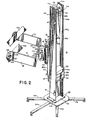
- FIGs. 1-3 The details of system 10 are shown in Figs. 1-3 in which an H-shaped beam forms a vertical column 12.
- Column 12 has opposing walls 12a,b with a flange 12c connecting the two walls together.
- Column 12 is supported at its bottom by a base assembly 20 having a base plate 22 and outwardly extending legs 24a-e.
- Column 12 is secured to plate 22 by bolts 22a for example.
- the rear of column 12 is closed by a U-shaped door 14 hinged to wall 12b by way of hinges 16.
- Test head 11 is supported and manipulated in its docking by a positioner arm assembly 30 which moves vertically on a main shaft 50.
- Assembly 30 comprises a main arm assembly 32, a forearm assembly 34, a wrist joint assembly 36, a cradle assembly 38 and test head adapter plates 40a,b.
- Main shaft 50 is secured by opposing pillow blocks 52, 53.
- Positioner arm assembly 30 is counterbalanced to ride vertically on main shaft 50 by a counter weight assembly 60 having a weight carriage 62 which moves vertically in either direction within the rear section of column 12.
- Carriage 62 has vertically extending carriage shafts 65a,b secured thereto and carries removable weights 62a-c. Weights 62a-c exactly counterbalance the weight of assembly 30 and test head 11 so that they are substantially weightless.
- shafts 65a,b threadedly receive members 67a,b swaged to respective ends of cables 68a,b received within grooves of pulleys 72a,b of assembly 70.
- Shaft 74 permits the rotation of pulleys 72a,b and the shaft is received at an upper end section of column 12.
- Cables 68a,b extend downwardly along the inner surface of walls 12a,b through openings in a plate 230 and are securely fastened by way of swaged members to a lift block 80 positioned under main arm assembly 32.
- Block 80 has an opening for receiving shaft 50 and the block slides along web 12c and is thus prevented from rotating around shaft 50.
- main arm assembly 32 includes an upper bearing block 86 and a lower bearing block 87 carried by block 80.
- a main shaft thrust bearing 80a is provided between blocks 80, 87.
- Blocks 86, 87 have respective lower extending and upper extending sections 86a, 87a and as shown engage an I beam 90.
- a front wall 90a of I beam 90 is secured to front faces of blocks 86, 87 while a rear section 90b of I beam 90 is secured to sections 86a, 87a.
- the vertical and rotational movements of assembly 32 may be temporarily locked in any position by means of a lock 55 formed in a block 91 as-later described in detail.
- a sleeve 226 concentric with shaft 50 is secured between blocks 87, 91 having inner linear bearings 228 which permit the sleeve to travel upwardly and downwardly on shaft 50. Further, sleeve 226 has thrust bearings 227. In this way a unitary main arm assembly 32 is formed which is adapted to have vertical movement and rotational movement (about a vertical axis) on a vertical shaft 50.
- a fluid cylinder 220 has one end fixed to pillow block 52 and the other end to plate 230 secured to the outer surface of sleeve 226. Cylinder 220 prevents rapid vertical movement of arm assembly 30 as a safety feature for operating personnel and to prevent damage to the handler and test head. Cylinder 220 may be a Bimba model 0920-DP, Bimba Manufacturing Co., Monea, Illinois.
- Forearm assembly 34 Secured to front face 90a are a pair of pillow blocks 95, 96 of forearm assembly 34.
- a vertical shaft 98 extends through pillow blocks 95, 96.
- Forearm assembly 34 further includes a forearm 100 having a rear section 101 which is bolted to forearm 100 by means of bolts.
- Shaft 98 extends through vertical opening 107 in section 101 with needle bearings at either end and a thrust bearing between section 101 and pillow block 96.
- Forearm assembly 34 may be temporarily fixed in its rotational position about a vertical axis by means of a forearm lock assembly 106.
- forearm assembly 34 may be effectively turned 180° while maintaining all the other elements in their original positions. In this manner, rear section 101 extends to the left as compared to the right as shown in Fig. 3.
- Forearm 100 has a front "C" shaped section which rotatively receives an attachment member 120 of wrist joint assembly 36.
- Member 120 rotates with respect to forearm 100 by way of vertical upper and lower pivot pins 122. Needle bearings are provided for the rotation of pins 122 in forearm 100 and a thrust bearing 128 is provided between member 120 and forearm 100.
- Member 120 may be temporarily prevented from rotation with respect to assembly 34 by means of a wrist joint lock assembly 110 which is formed within a block 112 secured to the upper surface of forearm 100.
- Member 120 has a longitudinal opening for receiving a horizontally extending shaft 300 which is rotated within needle bearings 302 and 304 secured to member 120.
- Shaft 300 at its outer end is welded to a connecting hub 310 for threadedly receiving cap screws 312 to rigidly secure back plate 130 of cradle assembly 38.
- Cradle assembly 38 is formed by three walls 130-132 welded together to form a U-shaped holder for the test head.
- Shaft 300 is effective to allow the rotation of assembly 38 about a horizontal axis and assembly 38 may be secured in position by tightening of cradle lock assembly 306 which is similar to assembly 55.
- Walls 131, 132 receive test head adapter plates 40a,b and allow these plates to rotate with respect to the walls and then to be rigidly fixed in position. Since the structure of both plates 40a,b are the same only one of them need be described.
- Arm 131 has within an end section a circular groove 135 and an opening 136 for receiving a shoulder screw 137.
- a lock knob 140 is threaded into plate 40a and moves about circular groove 135 in conventional manner. In this way, by tightening lock knob 140, plate 40a is rigidly secured with respect to wall 131.
- test head positioner system 10 simultaneously positions in six degrees of freedom, X, Y, Z, 8 x , 8y, 8 z .
- the test connector 11 a have that six degrees of freedom so that it can accurately and effortlessly be positioned with respect to the device to be tested, 15a for example.
- the Y direction were considered to be the vertical or up/ down direction then the movement of assembly 32 vertically with respect to shaft 50 provides the Y direction of freedom.
- 8y freedom which is the rotation about the Y axis is then provided by simultaneous rotation of all of the joints about vertical axes 50, 98 and 122.
- a main arm assembly lock 55 which comprises a conventional wedge lock system.
- two wedges 150 and 152 are provided on either side of shaft 50 and are threadedly engaged by threads 154 of a lock handle 153.
- lock handle 153 By turning lock handle 153 clockwise, wedge members 150, 152 are brought together and apply pressure onto shaft 50 and this way prevent rotation of block 91 about shaft 50 and also prevent a vertical movement of block 91 and the entire assembly 30.
- Similar lock assemblies are provided for forearm lock assembly 106, wrist joint lock assembly 110 and cradle lock assembly 306 which have turning arms 106a, 110a, 306a respectively.
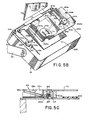
- mechanism 17 comprises a handler back plate 17a and a docking gusset assembly 17b.
- Plate 17a carries a device 15a to be tested which is electrically connected through movable contacts to male connectors 15b fixed to the back plane of plate 17a.
- Assembly 17b has an opening 200 to allow access to connectors 15b and effectively provides the back plane with gussets or blocks 202a,b by bolting assembly 17 to the back plane of plate 17a.
- similar gussets may, in a further embodiment, be mounted directly to the back plane.
- Each of gussets 202a,b has a centrally located guide opening 204a,b and are adapted to receive guide or location pins 11 of test head 11.
- test head 11 has a docking assembly 205 and test connectors 11 a which are mounted on a test head face plate 206.
- Guide pins 11 are effective to accurately locate connectors 11 a with handler connectors 15b.
- connectors 11 a, 15b are very fragile and must be mated with great accuracy to avoid damage. This is particularly a problem in view of the weight and mass of test head 15. Accordingly, guide pins 11b and blocks 202a,b are effective to keep the connectors 11a, 15b separated from each other until the pins 11b are actually received in guide openings 204a,b which ensures alignment and positive precise connection of connectors 11a, 15b. When pins 11b are aligned in the openings, it is then necessary to pull connectors 11a, 15b together. This is accomplished by means of a cam assembly 210 mounted on plate 206 which receives cam follower pins 206a,b which extend outwardly from blocks 202a,b.
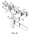
- Assembly 210 comprises a pair of cylindrical cams 212a,b journaled at their centers to fixed pivots and which synchronously operate by way of an endless cable 214.
- Each of the cams has a lower groove for receiving cable 214 which is tautly coupled between the cams by way of pulleys 214a-d, as shown.
- Each cam 212a,b has an outwardly extending handle 215a,b so that rotation of either handles operates both cams in synchronism with a mechanical advantage of, for example, 5:1.
- Each cam 212a,b has a slide helical groove 216a,b with an upper cut-out on the upper face for respectively receiving pins 206a,b when pins 11b b are in openings 204a,b.
- the cams Upon turning of one of the handles 215a,b the cams operate in synchronism to pull test head 11 into the plane of handler mechanism plate 17, thereby bringing both connectors 11a, 15b together into mating relationship. After mating, many devices 15a may then be tested by the handler system. In order to change test configurations, it is then necessary to disconnect connectors 11a, 15b and then remove the handler from the test head. Accordingly, one of the handles is operated to pull plate 17a from plate 206 thereby disconnecting connector 11 a from 15b.
- Each of the guide pins 11b is calibratable and includes an outer pin housing 203 having an inner chamber which receives a guide pin mount 207 having an outer diameter substantially less than the inner diameter of the chamber.
- Mount 207 has an inner chamber for receiving a cap screw 209 which extends through an opening which provides substantial clearance. Thus screw 209 may be loosened so that housing 203 may be precisely aligned on plate 206.
- a base 22c which is directly bolted onto the floor immediately next to test cabinet 11 c of the test system.
- a base 22c has attached to its lower surface along one side a rigid horizontal bar or leg 160.
- Mounting bolts 162 are used to secure bar 160 to the bottom of cabinet 11c.
- a leveling pad 164 remote from bar 160 provides leveling.
- a further strut 165 is secured to cabinet 11c and to wall 12a of column 12. In this manner, column 12 is secured close to cabinet 11c so that system 10 is as close as possible to the test system.
- Fig. 7A there is shown base 22b which is directly bolted onto the floor immediately next to test cabinet 11 c of the test system.
- a base 22c has attached to its lower surface along one side a rigid horizontal bar or leg 160.
- Mounting bolts 162 are used to secure bar 160 to the bottom of cabinet 11c.
- a leveling pad 164 remote from bar 160 provides leveling.
- a further strut 165 is secured to cabinet 11c and
- a base 22d has connected to its lower surface perpendicular legs 170, 171 coupled to adjacent sidewalls of test cabinet 11c.
- a leveling pad 174 is provided.
- bars 170,171 may be extended to the ends of the cabinet as shown in Fig. 7D as bars 170a, 171a. These bars are bolted to each other and also bolted to two additional bars 173, 175 which secure the remaining two sides of the cabinet. In this way, the four bars 170a, 171 a, 173 and 175 are bolted to each other to rigidly engage cabinet 11c to base 22e.
- FIG. 9 Still another embodiment of the invention is shown in Fig. 9 in which system 250 replaces the weights and cable assembly 60, 68a,b of system 10 with a pressurized cylinder 251 having a piston 252.
- Cylinder 251 effectively provides the same function as counterbalance assembly 60 in that it produces a constant force on arm assembly 30a (including test head 11) counter to gravity regardless of the actual position of the assembly.
- the balancing of different weights of assembly 30a may be accomplished by maintaining a constant pressure within the cylinder 251 by means of a regulator 258 supplied by pump 257 and described in detail with respect to Figs. 10, 11.
- Cylinder 251 is rigidly secured to central web 12c' of column 12 of Fig. 1.
- Piston 252 extends upwardly and is fixedly connected to a horizontal arm 254 which extends through a slot 256 formed in web 12c'.
- arm 254 is fixedly welded to sleeve 226, Figs. 1, 8.
- system 250 is substantially similar to system 10.
- FIG. 10-11 there is shown a further embodiment in which vertical column 12 of system 10 is in system 400 replaced by a vertically displaced cylindrical support tube 403.
- Tube 403 forms a cylinder for a piston and telescoping rod 402 with seals 414a,b.
- support tube 403 is supported at its bottom by a base assembly 20b having extending legs 24a-e.
- Tube 403 and piston 402 operate the same as tube 251 and piston 252.
- a fluid cavity 412 is formed between the piston and cylinder. Fluid under pressure flows into and out of the cavity from a fluid souce coupled by way of a line 407 through a regulator 404, and pressure gauge 406 to cavity 412.
- regulator 404 has an opening to atmosphere 404a which allows pressure from cavity 412 to be released when it is in excess of the regulator setting 404b.
- the fluid is air under a pressure of 175-690 kPa (25-100 pounds per square inch). This would accommodate a total weight of arm assembly 405 including a test head where the test head weighs from 75-300 pounds. In this manner there is achieved a constant pressure "gas spring" so that positioner arm assembly 405 effectively achieves weightlessness.
- assembly 405 may have a 15-20 inch travel.
- damper 220a having a damper rod 222a which is similar to that shown in Figs. 1 and 8.
- the top end of damper 220a is journaled in a bearing 418 connected to an upper plate 424 of arm assembly 405. In this manner, damper 220a is effective to damp the movement of assembly 405 while the rotation of the assembly does not adversely twist rod 222a.
- Assembly 405 is similar to assembly 30 but has been designed for further simplicity. Specifically, rotation and vertical movement of rod 402 may be locked by a lock assembly 416, as shown.
- the upper section of piston 402 is rigidly secured to mount block 426 to which is secured bearing mount plates 428, 430.
- Plate 428 has secured to its outer face bearing blocks 428a,b and similarly plate 430 has blocks 430a,b. These blocks have linear bearings for receiving horizontal shafts 432, 434 respectively.
- Locking block 437 secured to plate 428 is effective to receive shaft 432 and prevent movement thereof when locked.
- Shafts 432, 434 are rigidly connected at their left end to a wrist mounting plate 440 which fixedly carries a wrist bearing block 442 having a lock assembly 443 similar to assembly 110.
- Block 442 has secured to an inner section thereof a wrist joint assembly 36a carrying a cradle assembly 38a which are similar to assemblies 36, 38 of system 10.
- Positioner system 450 is suitable for relatively lightweight test heads since it is a simplified construction having a single shaft 432a horizontally journaled in blocks 429a,b and 452. Blocks 429a,b and 452 are carried by and secured to a mount block 426a which is supported by piston 402. The horizontal and rotational movement of the shaft 432a is locked by previously described wedge lock system 55a within block 452. Further, the end of shaft 432a is rigidly secured to a wrist bearing block 440a.
- Block 440a supports a simplified wrist joint assembly 460 which carries cradle assembly 38b. Suitable locks are provided in blocks 440a, 460 and assembly 38b in the manner previously described.
Claims (9)
Priority Applications (6)
| Application Number | Priority Date | Filing Date | Title |
|---|---|---|---|
| AT83304739T ATE34867T1 (de) | 1982-08-25 | 1983-08-16 | Positionierer fuer elektronische testkoepfe von testsystemen. |
| AT87100160T ATE75341T1 (de) | 1982-08-25 | 1983-08-16 | Einstellvorrichtung fuer elektronische testkoepfe. |
| DE8383304739T DE3376908D1 (en) | 1982-08-25 | 1983-08-16 | Electronic test head positioner for test systems |
| MYPI91000540A MY105364A (en) | 1982-08-25 | 1988-12-31 | Electronic test head positioner for test systems. |
| MYPI91000539A MY111869A (en) | 1982-08-25 | 1988-12-31 | Electronic test head positioner for test systems. |
| SG119992A SG119992G (en) | 1982-08-25 | 1992-11-20 | Electronic test head positioner for test systems |
Applications Claiming Priority (4)
| Application Number | Priority Date | Filing Date | Title |
|---|---|---|---|
| US411311 | 1982-08-25 | ||
| US06/411,311 US4527942A (en) | 1982-08-25 | 1982-08-25 | Electronic test head positioner for test systems |
| US522635 | 1983-08-11 | ||
| US06522635 US4589815B1 (en) | 1982-08-25 | 1983-08-11 | Electronic test head positioner for test systems |
Related Child Applications (2)
| Application Number | Title | Priority Date | Filing Date |
|---|---|---|---|
| EP87100160.8 Division-Into | 1983-08-16 | ||
| EP87100158.2 Division-Into | 1983-08-16 |
Publications (2)
| Publication Number | Publication Date |
|---|---|
| EP0102217A1 EP0102217A1 (de) | 1984-03-07 |
| EP0102217B1 true EP0102217B1 (de) | 1988-06-01 |
Family
ID=27021358
Family Applications (1)
| Application Number | Title | Priority Date | Filing Date |
|---|---|---|---|
| EP83304739A Expired EP0102217B1 (de) | 1982-08-25 | 1983-08-16 | Positionierer für elektronische Testköpfe von Testsystemen |
Country Status (6)
| Country | Link |
|---|---|
| EP (1) | EP0102217B1 (de) |
| DE (2) | DE3382731T2 (de) |
| HK (3) | HK76989A (de) |
| IL (1) | IL69592A (de) |
| MY (1) | MY103959A (de) |
| SG (2) | SG15989G (de) |
Cited By (1)
| Publication number | Priority date | Publication date | Assignee | Title |
|---|---|---|---|---|
| CN111745402A (zh) * | 2020-07-16 | 2020-10-09 | 徐绍波 | 数控单臂工作台移动式复合立车 |
Families Citing this family (20)
| Publication number | Priority date | Publication date | Assignee | Title |
|---|---|---|---|---|
| US4715574A (en) * | 1985-11-12 | 1987-12-29 | Intest Corporation | Safety lock for materials handling system |
| DE3615941A1 (de) * | 1986-05-12 | 1987-11-19 | Willberg Hans Heinrich | Geraet zum pruefen von elektronischen bauelementen, insbesondere ic's |
| DE3638430A1 (de) * | 1986-11-11 | 1988-05-19 | Multitest Elektronische Syst | Vorrichtung zum testen und sortieren von elektronischen bauelementen, insbesondere ic's |
| FR2620825B1 (fr) * | 1987-09-17 | 1990-08-03 | Schlumberger Ind Sa | Colonne de support pour appareil manipulateur d'une tete d'equipement de test automatique |
| US4943020A (en) * | 1987-09-17 | 1990-07-24 | Schlumberger Technologies, Inc. | Manipulator apparatus |
| US4893074A (en) * | 1988-05-13 | 1990-01-09 | Intest Corporation | Electronic device testing system |
| DE3912589A1 (de) * | 1989-04-17 | 1990-10-25 | Ekkehard Ueberreiter | Einrichtung zum testen von elektronischen bauelementen mit einer ladestation, einer teststation und eine entladestation fuer die bauelemente |
| FR2652529B1 (fr) * | 1989-10-02 | 1992-02-07 | Vega Automation | Robot. |
| DE4301490A1 (de) * | 1993-01-21 | 1994-07-28 | Insta Elektro Gmbh & Co Kg | Passivinfrarot-Gerätesystem |
| US5440943A (en) * | 1993-09-15 | 1995-08-15 | Intest Corporation | Electronic test head manipulator |
| US5600258A (en) * | 1993-09-15 | 1997-02-04 | Intest Corporation | Method and apparatus for automated docking of a test head to a device handler |
| US6271657B1 (en) | 1997-07-25 | 2001-08-07 | Advantest Corporation | Test head positioner for semiconductor device testing apparatus |
| DE10122049B4 (de) * | 2001-05-07 | 2004-08-19 | Heigl, Helmuth, Dr.-Ing. | Vorrichtung zum Verriegeln von zwei miteinander zu koppelnden Einrichtungen, insbesondere eines Testkopfs und einer Prüfeinrichtung |
| DE10205115B4 (de) * | 2002-02-07 | 2005-10-06 | Kupka, Harald | Kopplungsvorrichtung für Platinen |
| DE10245865B4 (de) * | 2002-09-30 | 2012-06-06 | Esmo Ag | Positionier- und Verriegelungsvorrichtung |
| DE102006005531B4 (de) | 2006-02-07 | 2013-01-17 | Vega Grieshaber Kg | 1 mFeldgerät mit einer Montageklammer zur Befestigung an einer Befestigungsfläche |
| CN103624776A (zh) * | 2013-12-23 | 2014-03-12 | 镇江艾科半导体有限公司 | 控制测试头在xy平面内精确运动定位的机械手臂 |
| CN107053246B (zh) * | 2017-03-09 | 2023-09-29 | 中国南方电网有限责任公司超高压输电公司梧州局 | 自复位自锁紧的输电线路绝缘子检测机器人旋转关节机构 |
| CN111271568B (zh) * | 2020-04-10 | 2021-08-27 | 叶子路 | 一种具有自适应调节的支撑装置及其使用方法 |
| CN112923964B (zh) * | 2021-01-25 | 2023-11-07 | 成都主导科技有限责任公司 | 一种轨道车辆检测系统的调节装置 |
Family Cites Families (2)
| Publication number | Priority date | Publication date | Assignee | Title |
|---|---|---|---|---|
| GB2074337B (en) * | 1980-04-15 | 1983-11-16 | Univ Technology | Adjustable support for an optical or other instrument |
| DE3048045C2 (de) * | 1980-12-19 | 1984-12-06 | Mora Fabrik für Meßgeräte Helmut Freund GmbH, 8750 Aschaffenburg | Höhenmeß- und Anreißgerät mit einer von einem Gerätefuß aufragenden Gerätesäule |
-
1983
- 1983-08-16 EP EP83304739A patent/EP0102217B1/de not_active Expired
- 1983-08-16 DE DE3382731T patent/DE3382731T2/de not_active Expired - Lifetime
- 1983-08-16 DE DE8787100160T patent/DE3382550D1/de not_active Expired - Lifetime
- 1983-08-29 IL IL69592A patent/IL69592A/xx not_active IP Right Cessation
-
1988
- 1988-12-31 MY MYPI88001612A patent/MY103959A/en unknown
-
1989
- 1989-03-15 SG SG159/89A patent/SG15989G/en unknown
- 1989-09-28 HK HK769/89A patent/HK76989A/xx not_active IP Right Cessation
-
1993
- 1993-03-11 HK HK215/93A patent/HK21593A/xx not_active IP Right Cessation
-
1995
- 1995-02-06 SG SG19595A patent/SG19595G/en unknown
- 1995-04-06 HK HK49395A patent/HK49395A/xx not_active IP Right Cessation
Cited By (1)
| Publication number | Priority date | Publication date | Assignee | Title |
|---|---|---|---|---|
| CN111745402A (zh) * | 2020-07-16 | 2020-10-09 | 徐绍波 | 数控单臂工作台移动式复合立车 |
Also Published As
| Publication number | Publication date |
|---|---|
| MY103959A (en) | 1993-10-30 |
| IL69592A0 (en) | 1983-11-30 |
| DE3382731T2 (de) | 1994-05-19 |
| SG19595G (en) | 1995-08-18 |
| HK21593A (en) | 1993-03-19 |
| SG15989G (en) | 1989-06-09 |
| HK49395A (en) | 1995-04-13 |
| EP0102217A1 (de) | 1984-03-07 |
| DE3382731D1 (de) | 1994-02-10 |
| DE3382550D1 (de) | 1992-05-27 |
| HK76989A (en) | 1989-10-06 |
| IL69592A (en) | 1988-02-29 |
Similar Documents
| Publication | Publication Date | Title |
|---|---|---|
| US4589815A (en) | Electronic test head positioner for test systems | |
| US4705447A (en) | Electronic test head positioner for test systems | |
| US5149029A (en) | Electronic test head positioner for test systems | |
| EP0102217B1 (de) | Positionierer für elektronische Testköpfe von Testsystemen | |
| US4588346A (en) | Positioner for maintaining an object in a substantially weightless condition | |
| US5450766A (en) | Test head manipulator | |
| EP0237698A2 (de) | Einstellvorrichtung für elektronische Testköpfe | |
| US7276894B2 (en) | Dynamic cradle assembly positioner system for positioning an electronic device test head | |
| US5606262A (en) | Manipulator for automatic test equipment test head | |
| EP0811167B1 (de) | Manipulator für einen testkopf einer automatischen testanlage | |
| US7340972B2 (en) | Apparatus and method for balancing and for providing a compliant range to a test head | |
| US8981807B2 (en) | Positioner system and method of positioning | |
| JPH08220190A (ja) | デバイスハンドラーへの試験ヘッドの自動ドッキング方法及び装置 | |
| US5608334A (en) | Device testing system with cable pivot and method of installation | |
| EP0237697A2 (de) | Positionierer für elektronische Testköpfe von Testsystemen | |
| KR20010012130A (ko) | 동작범위가 넓은 매니퓰레이터 | |
| US6646431B1 (en) | Test head manipulator | |
| EP1601980B1 (de) | Handgelenk zum anbringen eines testkopfes | |
| EP1712923B1 (de) | Vorrichtung und Verfahren zum Ausbalancieren und Bereitstellung eines konformen Bereichs für einen Prüfkopf | |
| SU765738A1 (ru) | Наклонно-поворотный стенд |
Legal Events
| Date | Code | Title | Description |
|---|---|---|---|
| PUAI | Public reference made under article 153(3) epc to a published international application that has entered the european phase |
Free format text: ORIGINAL CODE: 0009012 |
|
| AK | Designated contracting states |
Designated state(s): AT BE CH DE FR GB IT LI LU NL SE |
|
| 17P | Request for examination filed |
Effective date: 19840719 |
|
| GRAA | (expected) grant |
Free format text: ORIGINAL CODE: 0009210 |
|
| AK | Designated contracting states |
Kind code of ref document: B1 Designated state(s): AT BE CH DE FR GB IT LI LU NL SE |
|
| REF | Corresponds to: |
Ref document number: 34867 Country of ref document: AT Date of ref document: 19880615 Kind code of ref document: T |
|
| ITF | It: translation for a ep patent filed |
Owner name: INTERPATENT ST.TECN. BREV. |
|
| REF | Corresponds to: |
Ref document number: 3376908 Country of ref document: DE Date of ref document: 19880707 |
|
| PG25 | Lapsed in a contracting state [announced via postgrant information from national office to epo] |
Ref country code: LU Free format text: LAPSE BECAUSE OF NON-PAYMENT OF DUE FEES Effective date: 19880831 |
|
| ET | Fr: translation filed | ||
| PLBE | No opposition filed within time limit |
Free format text: ORIGINAL CODE: 0009261 |
|
| STAA | Information on the status of an ep patent application or granted ep patent |
Free format text: STATUS: NO OPPOSITION FILED WITHIN TIME LIMIT |
|
| 26N | No opposition filed | ||
| ITTA | It: last paid annual fee | ||
| EAL | Se: european patent in force in sweden |
Ref document number: 83304739.2 |
|
| NLS | Nl: assignments of ep-patents |
Owner name: INTEST IP CORPORATION |
|
| REG | Reference to a national code |
Ref country code: FR Ref legal event code: TP |
|
| BECA | Be: change of holder's address |
Free format text: 20010531 *IN TEST IP CORP. UNE SOC. DE L'ETAT DE DELAWARE:300 DELAWARE AVENUE, WILMINGTON DE 19801 |
|
| REG | Reference to a national code |
Ref country code: GB Ref legal event code: IF02 |
|
| REG | Reference to a national code |
Ref country code: CH Ref legal event code: PUE Owner name: INTEST CORPORATION TRANSFER- INTEST IP CORPORATION |
|
| REG | Reference to a national code |
Ref country code: GB Ref legal event code: 732E |
|
| PGFP | Annual fee paid to national office [announced via postgrant information from national office to epo] |
Ref country code: SE Payment date: 20020806 Year of fee payment: 20 |
|
| PGFP | Annual fee paid to national office [announced via postgrant information from national office to epo] |
Ref country code: FR Payment date: 20020808 Year of fee payment: 20 |
|
| PGFP | Annual fee paid to national office [announced via postgrant information from national office to epo] |
Ref country code: AT Payment date: 20020813 Year of fee payment: 20 |
|
| PGFP | Annual fee paid to national office [announced via postgrant information from national office to epo] |
Ref country code: GB Payment date: 20020814 Year of fee payment: 20 |
|
| PGFP | Annual fee paid to national office [announced via postgrant information from national office to epo] |
Ref country code: CH Payment date: 20020815 Year of fee payment: 20 |
|
| PGFP | Annual fee paid to national office [announced via postgrant information from national office to epo] |
Ref country code: DE Payment date: 20020821 Year of fee payment: 20 |
|
| PGFP | Annual fee paid to national office [announced via postgrant information from national office to epo] |
Ref country code: NL Payment date: 20020829 Year of fee payment: 20 |
|
| PGFP | Annual fee paid to national office [announced via postgrant information from national office to epo] |
Ref country code: BE Payment date: 20021017 Year of fee payment: 20 |
|
| PG25 | Lapsed in a contracting state [announced via postgrant information from national office to epo] |
Ref country code: LI Free format text: LAPSE BECAUSE OF EXPIRATION OF PROTECTION Effective date: 20030815 Ref country code: GB Free format text: LAPSE BECAUSE OF EXPIRATION OF PROTECTION Effective date: 20030815 Ref country code: CH Free format text: LAPSE BECAUSE OF EXPIRATION OF PROTECTION Effective date: 20030815 |
|
| PG25 | Lapsed in a contracting state [announced via postgrant information from national office to epo] |
Ref country code: NL Free format text: LAPSE BECAUSE OF EXPIRATION OF PROTECTION Effective date: 20030816 Ref country code: AT Free format text: LAPSE BECAUSE OF EXPIRATION OF PROTECTION Effective date: 20030816 |
|
| REG | Reference to a national code |
Ref country code: GB Ref legal event code: PE20 |
|
| REG | Reference to a national code |
Ref country code: CH Ref legal event code: PL |
|
| EUG | Se: european patent has lapsed | ||
| NLV7 | Nl: ceased due to reaching the maximum lifetime of a patent |
Effective date: 20030816 |