EP0102165A1 - Speed detection apparatus and method - Google Patents
Speed detection apparatus and method Download PDFInfo
- Publication number
- EP0102165A1 EP0102165A1 EP83304100A EP83304100A EP0102165A1 EP 0102165 A1 EP0102165 A1 EP 0102165A1 EP 83304100 A EP83304100 A EP 83304100A EP 83304100 A EP83304100 A EP 83304100A EP 0102165 A1 EP0102165 A1 EP 0102165A1
- Authority
- EP
- European Patent Office
- Prior art keywords
- speed
- pulses
- period
- motor
- position pulses
- Prior art date
- Legal status (The legal status is an assumption and is not a legal conclusion. Google has not performed a legal analysis and makes no representation as to the accuracy of the status listed.)
- Withdrawn
Links
Images

Classifications
-
- G—PHYSICS
- G01—MEASURING; TESTING
- G01P—MEASURING LINEAR OR ANGULAR SPEED, ACCELERATION, DECELERATION, OR SHOCK; INDICATING PRESENCE, ABSENCE, OR DIRECTION, OF MOVEMENT
- G01P3/00—Measuring linear or angular speed; Measuring differences of linear or angular speeds
- G01P3/42—Devices characterised by the use of electric or magnetic means
- G01P3/44—Devices characterised by the use of electric or magnetic means for measuring angular speed
- G01P3/48—Devices characterised by the use of electric or magnetic means for measuring angular speed by measuring frequency of generated current or voltage
- G01P3/481—Devices characterised by the use of electric or magnetic means for measuring angular speed by measuring frequency of generated current or voltage of pulse signals
- G01P3/489—Digital circuits therefor
-
- G—PHYSICS
- G05—CONTROLLING; REGULATING
- G05B—CONTROL OR REGULATING SYSTEMS IN GENERAL; FUNCTIONAL ELEMENTS OF SUCH SYSTEMS; MONITORING OR TESTING ARRANGEMENTS FOR SUCH SYSTEMS OR ELEMENTS
- G05B19/00—Programme-control systems
- G05B19/02—Programme-control systems electric
- G05B19/18—Numerical control [NC], i.e. automatically operating machines, in particular machine tools, e.g. in a manufacturing environment, so as to execute positioning, movement or co-ordinated operations by means of programme data in numerical form
- G05B19/19—Numerical control [NC], i.e. automatically operating machines, in particular machine tools, e.g. in a manufacturing environment, so as to execute positioning, movement or co-ordinated operations by means of programme data in numerical form characterised by positioning or contouring control systems, e.g. to control position from one programmed point to another or to control movement along a programmed continuous path
- G05B19/21—Numerical control [NC], i.e. automatically operating machines, in particular machine tools, e.g. in a manufacturing environment, so as to execute positioning, movement or co-ordinated operations by means of programme data in numerical form characterised by positioning or contouring control systems, e.g. to control position from one programmed point to another or to control movement along a programmed continuous path using an incremental digital measuring device
- G05B19/23—Numerical control [NC], i.e. automatically operating machines, in particular machine tools, e.g. in a manufacturing environment, so as to execute positioning, movement or co-ordinated operations by means of programme data in numerical form characterised by positioning or contouring control systems, e.g. to control position from one programmed point to another or to control movement along a programmed continuous path using an incremental digital measuring device for point-to-point control
- G05B19/231—Numerical control [NC], i.e. automatically operating machines, in particular machine tools, e.g. in a manufacturing environment, so as to execute positioning, movement or co-ordinated operations by means of programme data in numerical form characterised by positioning or contouring control systems, e.g. to control position from one programmed point to another or to control movement along a programmed continuous path using an incremental digital measuring device for point-to-point control the positional error is used to control continuously the servomotor according to its magnitude
- G05B19/232—Numerical control [NC], i.e. automatically operating machines, in particular machine tools, e.g. in a manufacturing environment, so as to execute positioning, movement or co-ordinated operations by means of programme data in numerical form characterised by positioning or contouring control systems, e.g. to control position from one programmed point to another or to control movement along a programmed continuous path using an incremental digital measuring device for point-to-point control the positional error is used to control continuously the servomotor according to its magnitude with speed feedback only
-
- G—PHYSICS
- G05—CONTROLLING; REGULATING
- G05B—CONTROL OR REGULATING SYSTEMS IN GENERAL; FUNCTIONAL ELEMENTS OF SUCH SYSTEMS; MONITORING OR TESTING ARRANGEMENTS FOR SUCH SYSTEMS OR ELEMENTS
- G05B2219/00—Program-control systems
- G05B2219/30—Nc systems
- G05B2219/37—Measurements
- G05B2219/37313—Derive speed from position
Definitions
- This invention relates to a speed detection apparatus and method for detecting speed information using position pulses obtained from a position detector. More particularly, the invention relates to a speed detection apparatus and method wherein speed can be detected with great accuracy over a wide range.
- FIG. 1 is a block diagram of a common servo control system.
- a servo motor 1 has a rotary encoder (position detector) 2 connected directly to its rotary shaft for producing position pulses PP, each of which is generated whenever the motor rotates by a predetermined amount.
- the pulses PP are applied to an arithmetic circuit 3, which proceeds to compute the difference between the number of pulses PP generated and a number of position command pulses PCMD obtained from an external unit, the computed difference being set in an error register 4.
- the digital data within the error register 4 are converted into an analog voltage by a digital-to-analog converter 5, and the resulting voltage is applied as a speed command voltage to a speed control circuit 7.
- a speed detecting circuit 6 detects the actual speed of the motor 1 and provides the speed control circuit 7 with a voltage equivalent thereto. The latter controls the speed of the servomotor 1 based on the difference between the speed command voltage and the voltage signal corresponding to the actual speed.
- the accuracy of speed feedback control depends upon the speed detecting precision of the speed detecting circuit 6. The accuracy of speed detection is therefore extremely important in servo control.
- a speed detection apparatus heretofore available in the art has a position detector for generating two signals displaced in phase from each other by ⁇ r/2 and having a frequency f proportional to the rotational speed of the motor.
- the two-phase signals are converting into signals of a frequency 4f by means of a quadrupling circuit.
- a frequency-to-voltage converter generates a voltage proportional to the frequency 4f, that is, a voltage (actual speed voltage) proportional to the rotational speed of the motor.
- a problem encountered in the foregoing prior-art arrangement is that, when the motor speed drops to a low value, the magnitude of the voltage signal produced by the frequency-to-voltage converter no longer remains proportional to the rotational speed of the motor but instead exhibits a sudden decline which diminishes the accuracy of measurement. Accordingly, rather than relying upon a frequency-to-voltage conversion, methods of detecting speed by digital processing using a microcomputer have been proposed as a more desirable expedient in view of LSI techniques.
- One such method performs detection by counting position pulses applied within a fixed period and then treating a value proportional to the counted value as speed information.
- the fixed period is shortened, however, the number of pulses applied within said period diminishes so that there is a decline in the accuracy of speed detection. This makes it necessary to lengthen the period.
- a longer period also lengthens detection time, thereby detracting from the stability of the speed detection system.
- a second detection method performs detection by monitoring the interval (i.e., period) at which position pulses are applied and then treating the reciprocal of the interval as speed information. With this method, however, the period of the position pulses shortens at high-speed rotation so that it becomes difficult to measure the period accurately at such time.
- an object of the present invention is to provide a speed detection apparatus and method through which speed can be detected in a short time and with great accuracy.
- Another object of the present invention is to provide a speed detection apparatus and method which allow use of a circuit arrangement, consisting of counters, registers and arithmetic circuitry, which is well-suited for application of LSI techniques..
- a further object of the present invention is to provide a speed detection apparatus and method wherein a minimum of only two counters need be provided, thereby affording an apparatus of a simple and inexpensive construction.
- the foregoing objects are attained by providing a system for detecting speed information based on position pulses from a position detector for the purpose of controlling the speed of a motor.
- the invention includes means receiving the position pulses as an input thereto for counting the number thereof within a fixed period To, means for measuring an interval Tl between a position pulse generated just prior to the fixed period To and an instant at which the period begins, and means for measuring an interval T2 between a final position pulse generated in the period To and an instant at which the period ends.
- TP represents reference pulses of a fixed period To, such as 0.5 msec.
- P P denotes position pulses produced by a position detector.
- the number N of position pulses PP applied during the period To are counted, an interval Tl is measured, namely the time between a position pulse Sl which occurs just prior to the onset of the measurement period, and the start of said period, namely the instant at which a reference pulse TP is generated, and an interval T2 is measured, this being the time between a position pulse S4, which is the last position pulse in the measurement period, and the end of said period.
- a length of time T required for the application of N position pulses is computed from the following: where To is the fixed period, which is a known quantity. If the time T is divided by the counted pulse number N, the result will be the period per position pulse, and the reciprocal of this period will be the position pulse frequency, namely speed information. Therefore, letting V represent the rotational speed of the motor, V will be obtained from the following: where K is a proportional constant.
- the invention shortens a fixed period to a value of, e.g., 0.5 msec., and computes the average value of the periods of the position pulses in the fixed period. This solves the problem of measurement accuracy at low speed as encountered with the first detection method, and eliminates a decline in measurement accuracy in the high speed region, as occurs in the second detection method.
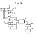
- Fig. 3 is a block diagram illustrating an embodiment of the present invention.
- Numeral 60 denotes an up/down counter for counting up forward rotation position pulses PP from the rotary encoder 2 (Fig. 1), and for counting down reverse rotation position pulses PP' from the rotary encoder, the counter being cleared by a reference pulse TP.
- the output of the up/down counter 60 is connected to the input side of a first register 61, in which the value of the count from the counter 60 is set in response to the reference pulse TP.
- a timer counter 62 counts clock pulses CP and has its contents cleared by either of the position pulses PP, PP', which are applied to an OR gate 67.
- the output of the timer counter 62 is connected to the input side of a second register 63, in which the value of the count from the timer counter 62 is set in response to the reference pulse TP.
- Numeral 64 designates an arithmetic circuit comprising a microprocessor for producing a signal indicative of speed information by executing the operations of Eqs. (1) and (2) using the contents of the first register 61 and second register 63.
- the output of the arithmetic circuit 64 is applied to a third register 65 for temporarily storing the speed information acquired from the arithmetic circuit 64.
- An analog-to-digital (DA) converter 66 converts the contents of the third register 65 into an analog value.
- the timer counter 62 counts the clock pulses CP and is cleared by each of the position pulses PP applied thereto via the OR gate 67. Meanwhile, the value of the count within the timer counter 62 is set in the second register 63 in response to each of the reference pulses TP. Therefore, at the instant the reference pulse Rl (Fig. 2) enters the second register 63, the second register 63 is set to a counted value Tl that is equivalent to the interval between a position pulse Sl and the reference pulse Rl.
- the arithmetic circuit 64 reads in the counted value Tl and stores the value in an internal memory.
- the up/down counter 60 counts up the position pulses PP and has its contents cleared by each of the the reference pulses TP.
- the counter 60 therefore counts the number of position pulses PP during the period To of the reference pulses TP, the value of the count being set in the first register 61 in response to each of the reference pulses TP.
- the timer counter 62 counts the clock pulses CP and is cleared by each of the position pulses PP, but the value of the count is not set in the second register 63 until the reference pulse TP arrives.
- the reference pulse TP is produced, the value of the count in the timer counter 62 is set in the second register 63.
- This value, represented by T2 corresponds to the interval between a position pulse S4 and a reference pulse R2, as shown in Fig. 2.
- the arithmetic circuit 64 reads in the counted value T2 from the second register 63, and computes the input time required T by executing the operation of Eq. (1) using the known period To as well as the previously counted value Tl stored in the internal memory.
- the arithmetic circuit 64 then goes to the first register 61 and reads in the number N of position pulses PP produced in the period extending from the reference pulse Rl to the reference pulse R2, and proceeds to obtain the speed information V by executing Eq. (2).
- the speed information V is fed into the third register 65 and is subsequently converted into an analog value by the DA converter 66.
- the analog value is then delivered to the speed control circuit 7 shown in Fig. 1. It should be noted that the DA converter 66 may be dispensed with if the speed control circuit 7 is to receive the speed information in digital form.
- the speed detection apparatus includes the up/down counter 60 for counting the number of position pulses applied thereto within the fixed period To, and a measurement circuit for measuring the time required for the entry of said number of position pulses, and for producing speed information based on a value obtained by dividing the number of position pulses by the measured time requirement.
- This arrangement makes possible a rapid and highly precise speed detection, and is particularly effective in improving the detection accuracy at high rotational speeds.
- the foregoing advantages can be achieved by a circuit arrangement, consisting of the counters, registers and arithmetic circuitry, which is well-suited for application of LSI techniques.
- a minimum of only counters are required, so that the circuit arrangement is simple and low in cost.
Landscapes
- Engineering & Computer Science (AREA)
- Physics & Mathematics (AREA)
- General Physics & Mathematics (AREA)
- Human Computer Interaction (AREA)
- Manufacturing & Machinery (AREA)
- Automation & Control Theory (AREA)
- Control Of Electric Motors In General (AREA)
- Linear Or Angular Velocity Measurement And Their Indicating Devices (AREA)
- Measuring Frequencies, Analyzing Spectra (AREA)
- Control Of Velocity Or Acceleration (AREA)
Abstract
Disclosed are a method and apparatus for providing speed information based on position pulses from a position detector for the purpose of controlling the speed of a motor. The invention includes means receiving the position pulses as an input thereto for counting the number thereof within a fixed period To, means for measuring an interval T1 between a position pulse generated just prior to the fixed period To and an instant at which the period begins, and means for measuring an interval T2 between a final position pulse generated in the period To and an instant at which the period ends. The operation T = To + T1 - T2 is performed to obtain the time T required for entry of the position pulses, the time T is divided by the number of pulses, and speed information V is obtained by performing the operation V = K.N/T, where K is a proportional constant.
Description
- This invention relates to a speed detection apparatus and method for detecting speed information using position pulses obtained from a position detector. More particularly, the invention relates to a speed detection apparatus and method wherein speed can be detected with great accuracy over a wide range.
- Controlling the speed of an A.C. or D.C. motor requires that the actual motor speed be detected and compared with a commanded speed. Fig. 1 is a block diagram of a common servo control system. A servo motor 1 has a rotary encoder (position detector) 2 connected directly to its rotary shaft for producing position pulses PP, each of which is generated whenever the motor rotates by a predetermined amount. The pulses PP are applied to an
arithmetic circuit 3, which proceeds to compute the difference between the number of pulses PP generated and a number of position command pulses PCMD obtained from an external unit, the computed difference being set in anerror register 4. The digital data within theerror register 4 are converted into an analog voltage by a digital-to-analog converter 5, and the resulting voltage is applied as a speed command voltage to aspeed control circuit 7. Meanwhile, using the position pulses PP from therotary encoder 2, aspeed detecting circuit 6 detects the actual speed of the motor 1 and provides thespeed control circuit 7 with a voltage equivalent thereto. The latter controls the speed of the servomotor 1 based on the difference between the speed command voltage and the voltage signal corresponding to the actual speed. In a servo control operation for performing control based on speed feedback in the above-described manner, the accuracy of speed feedback control depends upon the speed detecting precision of thespeed detecting circuit 6. The accuracy of speed detection is therefore extremely important in servo control. - A speed detection apparatus heretofore available in the art has a position detector for generating two signals displaced in phase from each other by τr/2 and having a frequency f proportional to the rotational speed of the motor. The two-phase signals are converting into signals of a frequency 4f by means of a quadrupling circuit. Finally, a frequency-to-voltage converter generates a voltage proportional to the frequency 4f, that is, a voltage (actual speed voltage) proportional to the rotational speed of the motor.
- A problem encountered in the foregoing prior-art arrangement is that, when the motor speed drops to a low value, the magnitude of the voltage signal produced by the frequency-to-voltage converter no longer remains proportional to the rotational speed of the motor but instead exhibits a sudden decline which diminishes the accuracy of measurement. Accordingly, rather than relying upon a frequency-to-voltage conversion, methods of detecting speed by digital processing using a microcomputer have been proposed as a more desirable expedient in view of LSI techniques.
- One such method performs detection by counting position pulses applied within a fixed period and then treating a value proportional to the counted value as speed information. When the fixed period is shortened, however, the number of pulses applied within said period diminishes so that there is a decline in the accuracy of speed detection. This makes it necessary to lengthen the period. However, a longer period also lengthens detection time, thereby detracting from the stability of the speed detection system.
- A second detection method performs detection by monitoring the interval (i.e., period) at which position pulses are applied and then treating the reciprocal of the interval as speed information. With this method, however, the period of the position pulses shortens at high-speed rotation so that it becomes difficult to measure the period accurately at such time.
- Accordingly, an object of the present invention is to provide a speed detection apparatus and method through which speed can be detected in a short time and with great accuracy.
- Another object of the present invention is to provide a speed detection apparatus and method which allow use of a circuit arrangement, consisting of counters, registers and arithmetic circuitry, which is well-suited for application of LSI techniques..
- A further object of the present invention is to provide a speed detection apparatus and method wherein a minimum of only two counters need be provided, thereby affording an apparatus of a simple and inexpensive construction.
- According to the present invention, the foregoing objects are attained by providing a system for detecting speed information based on position pulses from a position detector for the purpose of controlling the speed of a motor. The invention includes means receiving the position pulses as an input thereto for counting the number thereof within a fixed period To, means for measuring an interval Tl between a position pulse generated just prior to the fixed period To and an instant at which the period begins, and means for measuring an interval T2 between a final position pulse generated in the period To and an instant at which the period ends. The operation T = To + Tl + T2 is performed to obtain the time T required for entry of the position pulses, the time T is divided by the number of pulses, and speed information V is obtained by performing the operation V = K-NJT, where K is a proportional constant.
- Other features and advantages of the present invention will be apparent from the following description taken in conjunction with the accompanying drawings.
- Fig. 1 is a block diagram of a common servo control system according to the prior art;
- Fig. 2 is a view of pulse timing useful in describing the principle of the present invention; and
- Fig. 3 is a block diagram illustrating an embodiment of a speed detection apparatus according to the present invention.
- With reference to Fig. 2, TP represents reference pulses of a fixed period To, such as 0.5 msec. PP denotes position pulses produced by a position detector. According to the present invention, the number N of position pulses PP applied during the period To are counted, an interval Tl is measured, namely the time between a position pulse Sl which occurs just prior to the onset of the measurement period, and the start of said period, namely the instant at which a reference pulse TP is generated, and an interval T2 is measured, this being the time between a position pulse S4, which is the last position pulse in the measurement period, and the end of said period. Then, using the values obtained from these measurements, a length of time T required for the application of N position pulses is computed from the following:


- Thus, the invention shortens a fixed period to a value of, e.g., 0.5 msec., and computes the average value of the periods of the position pulses in the fixed period. This solves the problem of measurement accuracy at low speed as encountered with the first detection method, and eliminates a decline in measurement accuracy in the high speed region, as occurs in the second detection method.
- Fig. 3 is a block diagram illustrating an embodiment of the present invention. Numeral 60 denotes an up/down counter for counting up forward rotation position pulses PP from the rotary encoder 2 (Fig. 1), and for counting down reverse rotation position pulses PP' from the rotary encoder, the counter being cleared by a reference pulse TP. The output of the up/down
counter 60 is connected to the input side of afirst register 61, in which the value of the count from thecounter 60 is set in response to the reference pulse TP. Atimer counter 62 counts clock pulses CP and has its contents cleared by either of the position pulses PP, PP', which are applied to anOR gate 67. The output of thetimer counter 62 is connected to the input side of asecond register 63, in which the value of the count from thetimer counter 62 is set in response to the reference pulse TP. Numeral 64 designates an arithmetic circuit comprising a microprocessor for producing a signal indicative of speed information by executing the operations of Eqs. (1) and (2) using the contents of thefirst register 61 andsecond register 63. The output of thearithmetic circuit 64 is applied to athird register 65 for temporarily storing the speed information acquired from thearithmetic circuit 64. An analog-to-digital (DA)converter 66 converts the contents of thethird register 65 into an analog value. - In operation, let us assume for the sake of convenience that the motor is rotating in the forward direction so that the position pulses are the forward rotation pulses PP. The
timer counter 62 counts the clock pulses CP and is cleared by each of the position pulses PP applied thereto via the ORgate 67. Meanwhile, the value of the count within thetimer counter 62 is set in thesecond register 63 in response to each of the reference pulses TP. Therefore, at the instant the reference pulse Rl (Fig. 2) enters thesecond register 63, thesecond register 63 is set to a counted value Tl that is equivalent to the interval between a position pulse Sl and the reference pulse Rl. Thearithmetic circuit 64 reads in the counted value Tl and stores the value in an internal memory. The up/downcounter 60 counts up the position pulses PP and has its contents cleared by each of the the reference pulses TP. Thecounter 60 therefore counts the number of position pulses PP during the period To of the reference pulses TP, the value of the count being set in thefirst register 61 in response to each of the reference pulses TP. Meanwhile, as described above, thetimer counter 62 counts the clock pulses CP and is cleared by each of the position pulses PP, but the value of the count is not set in thesecond register 63 until the reference pulse TP arrives. When the reference pulse TP is produced, the value of the count in thetimer counter 62 is set in thesecond register 63. This value, represented by T2, corresponds to the interval between a position pulse S4 and a reference pulse R2, as shown in Fig. 2. Thearithmetic circuit 64 reads in the counted value T2 from thesecond register 63, and computes the input time required T by executing the operation of Eq. (1) using the known period To as well as the previously counted value Tl stored in the internal memory. Thearithmetic circuit 64 then goes to thefirst register 61 and reads in the number N of position pulses PP produced in the period extending from the reference pulse Rl to the reference pulse R2, and proceeds to obtain the speed information V by executing Eq. (2). The speed information V is fed into thethird register 65 and is subsequently converted into an analog value by theDA converter 66. The analog value is then delivered to thespeed control circuit 7 shown in Fig. 1. It should be noted that theDA converter 66 may be dispensed with if thespeed control circuit 7 is to receive the speed information in digital form. - Operation is quite the same for reverse rotation of the motor. In such case the up/down
counter 60 will count down the position pulses PP' and deliver a negative counted value to thearithmetic circuit 64. This will provide speed information for reverse motor rotation. - In accordance with the present invention as described and illustrated hereinabove, the speed detection apparatus includes the up/down counter 60 for counting the number of position pulses applied thereto within the fixed period To, and a measurement circuit for measuring the time required for the entry of said number of position pulses, and for producing speed information based on a value obtained by dividing the number of position pulses by the measured time requirement. This arrangement makes possible a rapid and highly precise speed detection, and is particularly effective in improving the detection accuracy at high rotational speeds. Further, according to the invention, the foregoing advantages can be achieved by a circuit arrangement, consisting of the counters, registers and arithmetic circuitry, which is well-suited for application of LSI techniques. In addition, a minimum of only counters are required, so that the circuit arrangement is simple and low in cost.
- As many apparently widely different embodiments of the present invention can be made without departing from the spirit and scope thereof, it is to be understood that the invention is not limited to the specific embodiments thereof except as defined in the appended claims.
Claims (7)
1. A speed detection apparatus in which the actual speed of a motor is detected from position pulses generated by a position detector operatively associated with the motor, and the actual speed is compared with a commanded speed in order to control the motor, comprising:
(a) means receiving the position pulses as an input thereto for counting the number thereof within a fixed period To;
(b) means for measuring an interval Tl between a position pulse generated just prior to the fixed period To and an instant at which said period begins;
(c) means for measuring an interval T2 between a final position pulse generated in the period Toand an instant at which said period ends;
(d) means for obtaining a time T required for input of the position pulses by performing an operation T = To + Tl - T2; and
(e) means for dividing the time T by said number of pulses, and for detecting actual speed V by performing an operation V = K.N/T, where K is a proportional constant.
2. The apparatus according to claim 1, wherein means (a) comprises a counter.
3. The apparatus according to claim 1, wherein means (b) comprises a timer counter.
4. The apparatus according to claim 1, wherein means (c) comprises a timer counter.
5. The apparatus according to claim 1, wherein means (d) comprises an arithmetic circuit.
6. The apparatus according to claim 1, wherein means (d) comprises an arithmetic circuit.
7. A speed detection method in which the actual speed of a motor is detected from position pulses generated by a position detector operatively associated with the motor, and the actual speed is compared with a commanded speed in order to control the motor, comprising the steps of:
(a) counting a number of input position pulses within a fixed period;
(b) measuring a time required for input of said number of position pulses;
(c) dividing said number of position pulses by said measured time; and
(d) sensing actual speed based on the quotient obtained in step (c).
Applications Claiming Priority (2)
| Application Number | Priority Date | Filing Date | Title |
|---|---|---|---|
| JP123284/82 | 1982-07-15 | ||
| JP57123284A JPS5913957A (en) | 1982-07-15 | 1982-07-15 | Speed detecting circuit |
Publications (1)
| Publication Number | Publication Date |
|---|---|
| EP0102165A1 true EP0102165A1 (en) | 1984-03-07 |
Family
ID=14856753
Family Applications (1)
| Application Number | Title | Priority Date | Filing Date |
|---|---|---|---|
| EP83304100A Withdrawn EP0102165A1 (en) | 1982-07-15 | 1983-07-14 | Speed detection apparatus and method |
Country Status (3)
| Country | Link |
|---|---|
| US (1) | US4503374A (en) |
| EP (1) | EP0102165A1 (en) |
| JP (1) | JPS5913957A (en) |
Families Citing this family (14)
| Publication number | Priority date | Publication date | Assignee | Title |
|---|---|---|---|---|
| JPS6038658A (en) * | 1983-08-10 | 1985-02-28 | Mitsubishi Electric Corp | Speed detecting apparatus |
| US4774446A (en) * | 1984-10-04 | 1988-09-27 | Pitney Bowes Inc. | Microprocessor controlled d.c. motor for controlling printing means |
| JPH06101948B2 (en) * | 1984-12-25 | 1994-12-12 | ソニー株式会社 | Time information detector |
| US4876494A (en) * | 1986-11-20 | 1989-10-24 | Unimation, Inc. | Position and velocity feedback system for a digital robot control |
| JPH02159990A (en) * | 1988-12-10 | 1990-06-20 | Fanuc Ltd | Speed control system of servo-motor |
| US4956592A (en) * | 1989-03-31 | 1990-09-11 | Midmark Corporation | Automatically positionable chair |
| JPH07175515A (en) * | 1993-12-17 | 1995-07-14 | Kobe Steel Ltd | Abnormality detecting method, stability calculating method, and operation control method for machine facility and roller mill |
| EP0825509B1 (en) * | 1996-08-19 | 2002-06-26 | Sirona Dental Systems GmbH | Precise positioning device for a manoeuvrable apparatus using electric motor drive |
| JP3700325B2 (en) * | 1997-05-21 | 2005-09-28 | 松下電器産業株式会社 | Drive source control method |
| JP2002531834A (en) * | 1998-12-02 | 2002-09-24 | エムティエス・システムズ・コーポレーション | Mixed speed estimation |
| US7425033B2 (en) | 2003-09-03 | 2008-09-16 | Intier Automotive Closures Inc. | Vehicle sunroof assembly |
| JP6894240B2 (en) * | 2017-01-06 | 2021-06-30 | Juki株式会社 | sewing machine |
| US20220122826A1 (en) * | 2020-10-01 | 2022-04-21 | Thermo Fisher Scientific (Bremen) Gmbh | Determining the Average Frequency of a Series of Pulses |
| GB202015555D0 (en) * | 2020-10-01 | 2020-11-18 | Thermo Fisher Scient Bremen Gmbh | Determining the average frequency of a series of pulses |
Citations (5)
| Publication number | Priority date | Publication date | Assignee | Title |
|---|---|---|---|---|
| US3829785A (en) * | 1972-04-28 | 1974-08-13 | Philips Corp | Circuit arrangement for digital frequency measurement |
| US3892952A (en) * | 1973-03-22 | 1975-07-01 | Nippon Denso Co | Digital differentiation circuit |
| DE2750157A1 (en) * | 1976-11-09 | 1978-05-24 | Girling Ltd | METHOD AND DEVICE FOR MEASURING THE FREQUENCY OF A PULSE SIGNAL, IN PARTICULAR FOR SPEED MEASUREMENTS |
| DE2949131A1 (en) * | 1979-12-06 | 1981-06-11 | Deuta-Werke Vorm. Deutsche Tachometerwerke Gmbh, 5070 Bergisch Gladbach | Train velocity measuring device - uses distance pulses counter over fixed interval in combination with time taken to travel known distance |
| EP0059433A1 (en) * | 1981-02-28 | 1982-09-08 | Hitachi, Ltd. | Speed detecting apparatus |
Family Cites Families (6)
| Publication number | Priority date | Publication date | Assignee | Title |
|---|---|---|---|---|
| US4315200A (en) * | 1978-08-29 | 1982-02-09 | Canon Kabushiki Kaisha | Servo control apparatus |
| JPS55109184A (en) * | 1979-02-13 | 1980-08-22 | Victor Co Of Japan Ltd | Rotational speed control system |
| JPS5917257B2 (en) * | 1979-08-03 | 1984-04-20 | 自動車電機工業株式会社 | automatic speed control device |
| US4376914A (en) * | 1980-03-11 | 1983-03-15 | Olympus Optical Company Ltd. | Motor control device |
| JPS5748664A (en) * | 1980-09-06 | 1982-03-20 | Yaskawa Electric Mfg Co Ltd | Pulse frequency detector |
| JPS59433A (en) * | 1982-06-23 | 1984-01-05 | Nippon Kokan Kk <Nkk> | Steel manhole assembly and its construction |
-
1982
- 1982-07-15 JP JP57123284A patent/JPS5913957A/en active Pending
-
1983
- 1983-07-14 EP EP83304100A patent/EP0102165A1/en not_active Withdrawn
- 1983-07-15 US US06/514,315 patent/US4503374A/en not_active Expired - Lifetime
Patent Citations (5)
| Publication number | Priority date | Publication date | Assignee | Title |
|---|---|---|---|---|
| US3829785A (en) * | 1972-04-28 | 1974-08-13 | Philips Corp | Circuit arrangement for digital frequency measurement |
| US3892952A (en) * | 1973-03-22 | 1975-07-01 | Nippon Denso Co | Digital differentiation circuit |
| DE2750157A1 (en) * | 1976-11-09 | 1978-05-24 | Girling Ltd | METHOD AND DEVICE FOR MEASURING THE FREQUENCY OF A PULSE SIGNAL, IN PARTICULAR FOR SPEED MEASUREMENTS |
| DE2949131A1 (en) * | 1979-12-06 | 1981-06-11 | Deuta-Werke Vorm. Deutsche Tachometerwerke Gmbh, 5070 Bergisch Gladbach | Train velocity measuring device - uses distance pulses counter over fixed interval in combination with time taken to travel known distance |
| EP0059433A1 (en) * | 1981-02-28 | 1982-09-08 | Hitachi, Ltd. | Speed detecting apparatus |
Also Published As
| Publication number | Publication date |
|---|---|
| US4503374A (en) | 1985-03-05 |
| JPS5913957A (en) | 1984-01-24 |
Similar Documents
| Publication | Publication Date | Title |
|---|---|---|
| EP0102165A1 (en) | Speed detection apparatus and method | |
| US4450403A (en) | Method and apparatus for determining rotational speed | |
| EP0058282A1 (en) | Engine rotational speed measurement system | |
| EP0208788A1 (en) | Speed control system for servo motors | |
| EP0341445B1 (en) | Method of and apparatus for measuring revolution speed | |
| US4457074A (en) | Method and apparatus for synchronizing the sensor movement of a pitch and/or concentricity measuring device for gears | |
| US4341995A (en) | Velocity profile analyzer | |
| EP0120692A2 (en) | Phase modulation type digital position detector | |
| US4994723A (en) | Digital servo system for controlling rotational speed of rotary body | |
| EP0078854A1 (en) | Speed detecting device | |
| US4642542A (en) | Velocity control systems | |
| EP0134029B1 (en) | Speed control arrangement and motor control system | |
| SU1019222A1 (en) | Measuring converter | |
| JP3339214B2 (en) | Servo motor control device | |
| SU1071961A1 (en) | Speed ratio meter | |
| JPH0716555B2 (en) | Sewing machine controller | |
| JP2002531834A (en) | Mixed speed estimation | |
| SU842916A1 (en) | Device for testing shaft angular position-to-code converters | |
| SU763797A1 (en) | Digital measuring instrument for determining relative velocity difference | |
| JP2550987B2 (en) | Signal gradient measuring instrument | |
| Veselov et al. | High-quality microprocessor system for position, velocity, and acceleration measurements of electric drives | |
| SU1520589A1 (en) | Device for monitoring instability of rotary speed of magnetic disk of storage | |
| SU1040417A1 (en) | Angular speed measuring device | |
| JPH0839298A (en) | Slide stop time measuring instrument of press machine | |
| SU1478142A1 (en) | Meter of small frequency deviations from prespecified values |
Legal Events
| Date | Code | Title | Description |
|---|---|---|---|
| PUAI | Public reference made under article 153(3) epc to a published international application that has entered the european phase |
Free format text: ORIGINAL CODE: 0009012 |
|
| AK | Designated contracting states |
Designated state(s): DE FR GB |
|
| 17P | Request for examination filed |
Effective date: 19840828 |
|
| STAA | Information on the status of an ep patent application or granted ep patent |
Free format text: STATUS: THE APPLICATION IS DEEMED TO BE WITHDRAWN |
|
| 18D | Application deemed to be withdrawn |
Effective date: 19860318 |
|
| RIN1 | Information on inventor provided before grant (corrected) |
Inventor name: SAKANO, TETSURO |